NAOJ GW Elog Logbook 3.2

Yuhang, Pierre, Eleonora P, and Aritomi
In the beginning, Matteo and Eleonora modified the TAMA PD by apply two resistors and this amplifies the AC signal. This activity increased the SNR and make it possible to lock the coherent control loop.
Then I and Chien-Ming make this amplification even larger again, but the amplification increased both signal and noise. After this, we found there is a bandwidth limitation of AC channel op-amp when we increase the gain.
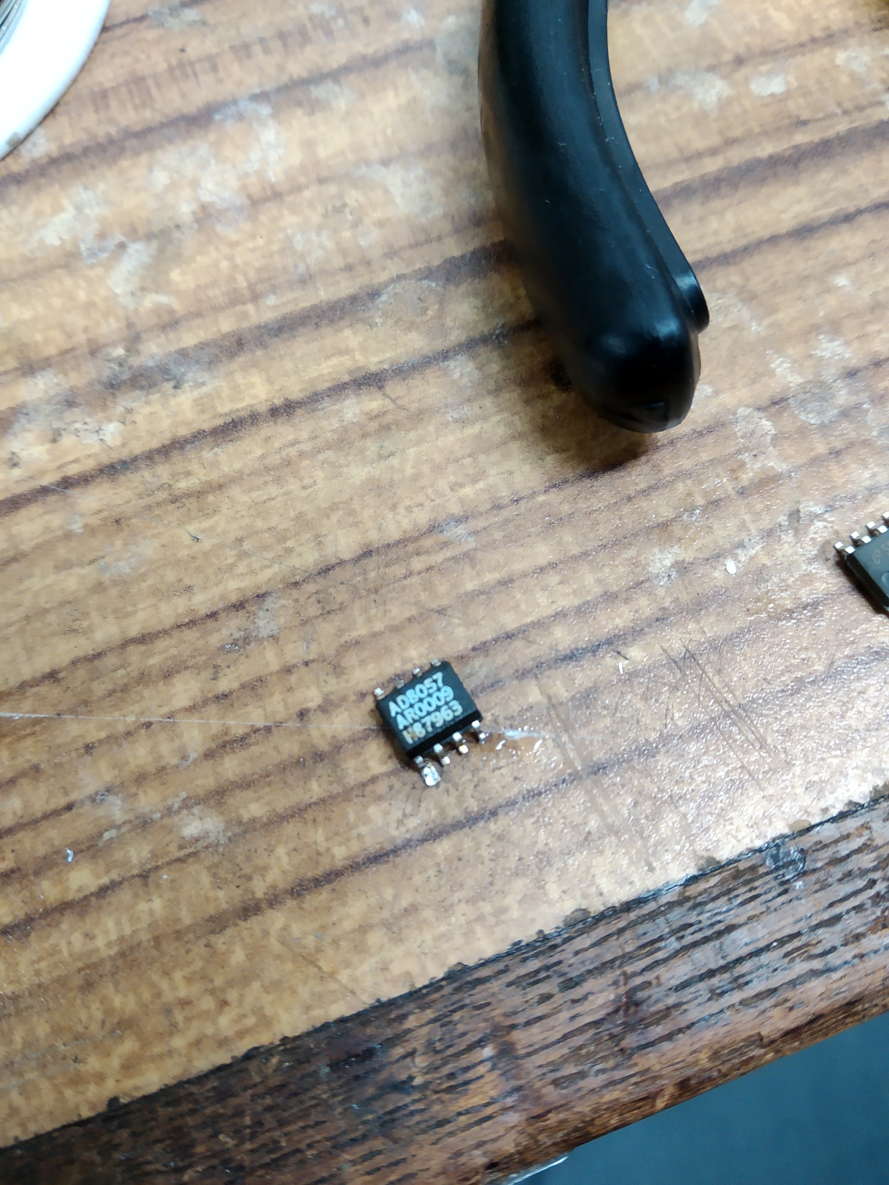
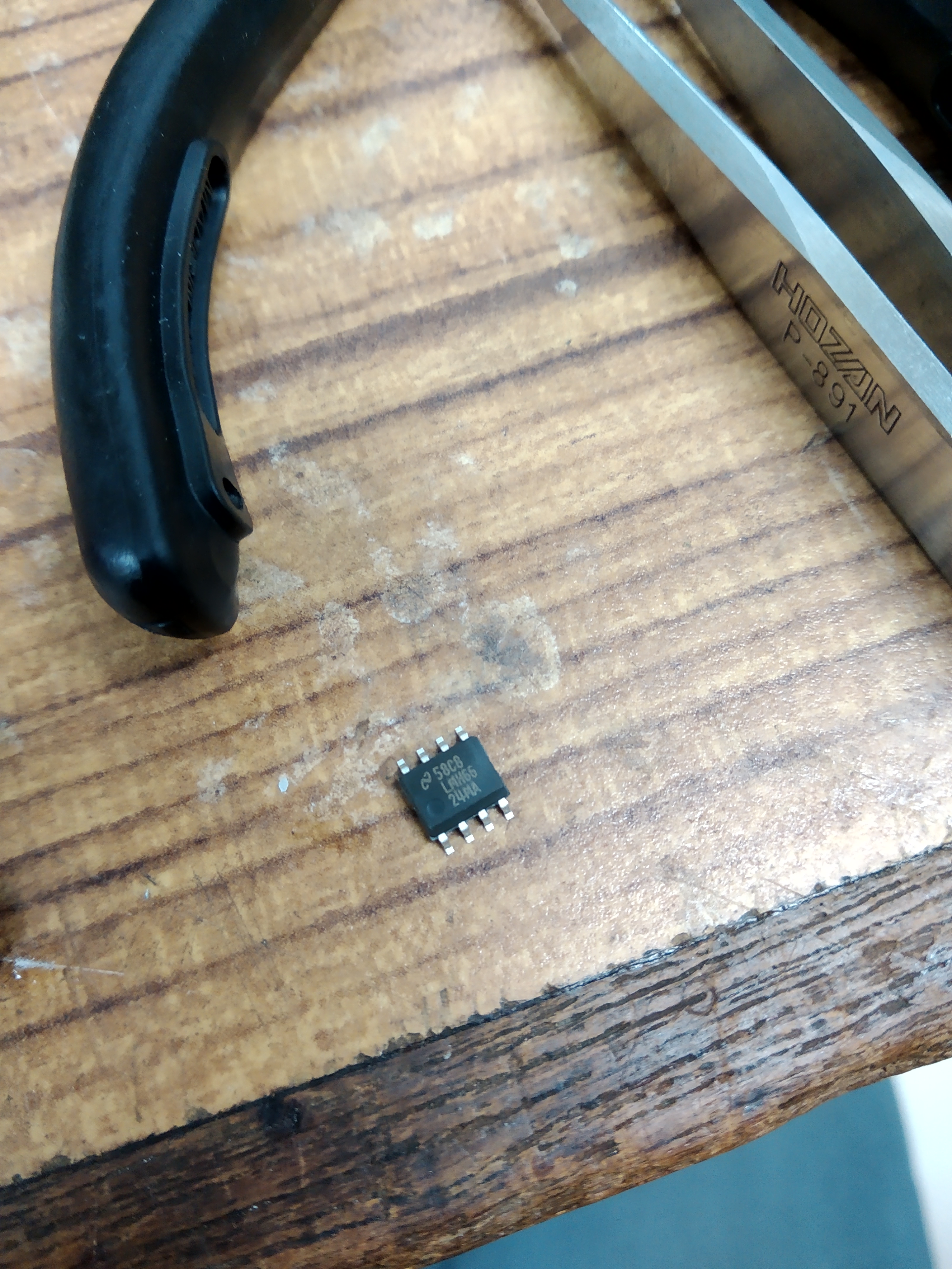
So we decide to use a higher speed op-amp and try to increase a bit the gain and to see if we can increase SNR furthermore. This replacement was did based on the modified PD improved by Chien-Ming. There were problems while Pierre was soldering the new op-amp. The copper board pin was fallen! But, fortunately, the lost pins are the pins which are not connected to anything else. Also, the day when we just finished the modification, we tested it on the bench but we didn't see any coherent control error signal. Actually, we found the very similar thing(cannot see BAB be amplified and de-amplified after OPO transmission) on the next workday. I and Aritomi-san we did the measurement of parametric (de)amplification measurement again while scanning the green phase with frequency slowly. After that, we could see everything well. We also realized at that time, the characterization of best OPO temperature/p-pol PLL locking frequency should be done maybe once a month.
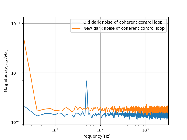
After the replacement, we characterized the dark noise and compare it with the old dark noise before replacement. We found an increase of dark noise, we think this may come from the rise of a large current bias on the op-amp.
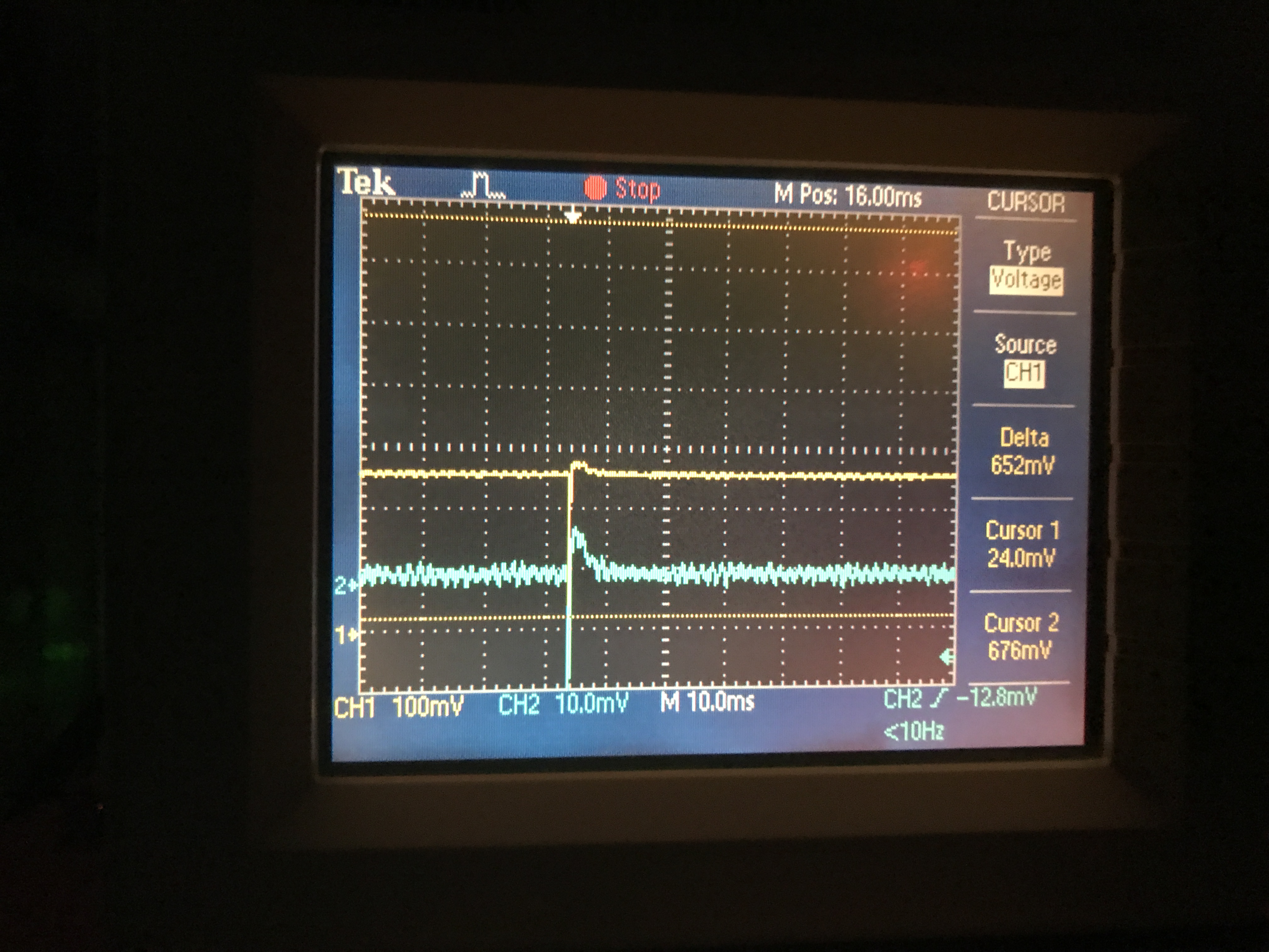
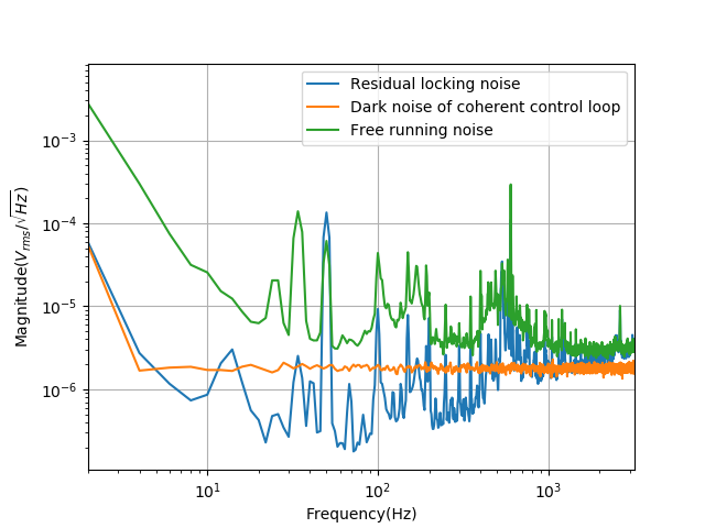
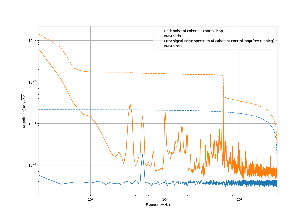
Then we measured the free-running noise and error signal noise spectrum (residual locking noise). The results are shown in the attached figures.
In the future,
we will also try to play a bit with the amplification of the AC signal. And also try to reduce the current bias of op-amp.
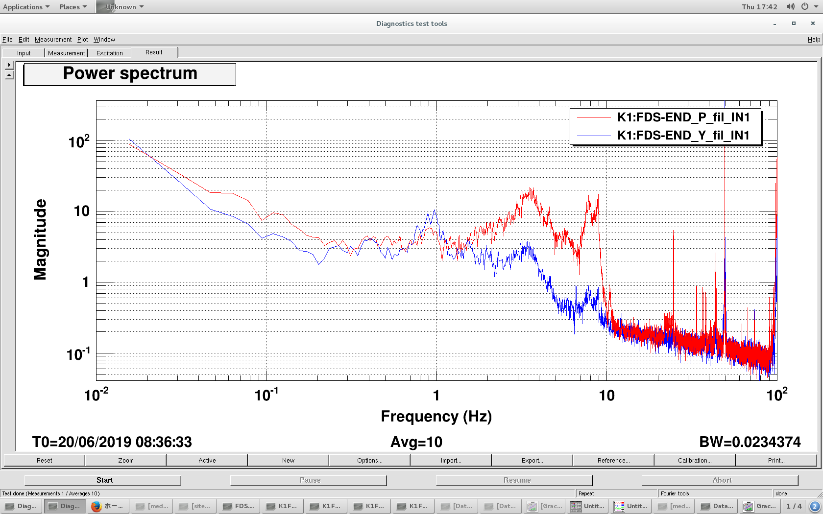
Error signal is 30 mVpp and conversion factor from V to rad is pi/0.03 = 105 rad/V.
[Takahashi-san, Yuhang, Eleonora C]
Last sunday afternoon (30/06) we recovered TAMA vacuum, air conditioning, dehumidifier system and DGS after the planned shutdown on 29/06.
Some details on the procedure can be found in the attached PDF.
Note that while I was In the end room I heard a short but very strong noise (as a small explosion). Takahashi-san told me that it is likely to be due to the presence of air bubble in the dehumidification water pump during the restarting process.

green setting:
| green power (mW) | OPO temperature (kOhm) | p pol PLL (MHz) |
| 40 | 7.175 | 174 |
IR into filter cavity is around 1 mW. TEM00 is as follows.
| AOM frequency (MHz) | IR transmission (cnt) |
| 109.03683 | 100-130 |
With 40mW green it was difficult to see higher order mode with IR camera. So we decided to increase green power.
On 27/06 Miyakawa-san came to Mitaka to try to fix the keyboard problem with the new DGS computer. (Since the gentoo linux cannot reconize the USB driver the keybord doesn't work). He tried to access the PC through the network but network port, but the kernel was too old to recognize it. It is not easy to update kernel because the kernel was patched to be a real time operation system. We also tried several USB PCIexpress board whitout success.
Anyway the actual standalone PC can host 4 ADC/DAC cards. Only two of them are currently used. We tested one of the new PCIexpress ADC board on the current stendalon PC and it seems to work fine. We decided to leave it installed.
The old ADC card is currently stored on the shelf close to the DGS rack.
In the near future we might need to install it too to increase the number of ADC channels. We agreed with Miyakawa-san and Akutsu-san that in this case we can use some of the hardwere from the ATC DGS which is currently unused.
In particular, in order to be able to use a second ADC we need 1 timiing adaptor, 1 AA module, 2 BNC-> Dsub coverter, cables. This will allow us to have 64 input channel.
Miyakawa-san showed me how to include additional ADC block in the simuling Real time model (NB: remember to copy the ADC block from library and not from those already in the model.)
He also helped to fix some minor issues:
1) remote connection to the DGS (Finaly we can access the system from the office and even from home!)
2) take/restore snapshot button on MEDM
3) rotation angle block
Yuhang and pierre
This work is motivated by the difficulty of locking the GRMC loop.
We measured again the loop, we found the resonant peaks have changed relative to the original measurement.
The first peak was changed from 7.23kHz to 6.9kHz and the second peak was changed from 11.85kHz to 9.9kHz.
We have already investigated by changing the position of clamps. But the peak position was not changed. However, I didn't try to move the end mirror of the mode cleaner. The change of these peaks position is still not clear.

Aritomi, EleonoraP, Yuhang
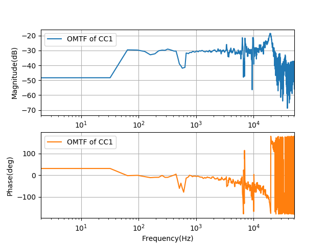
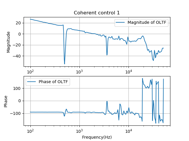
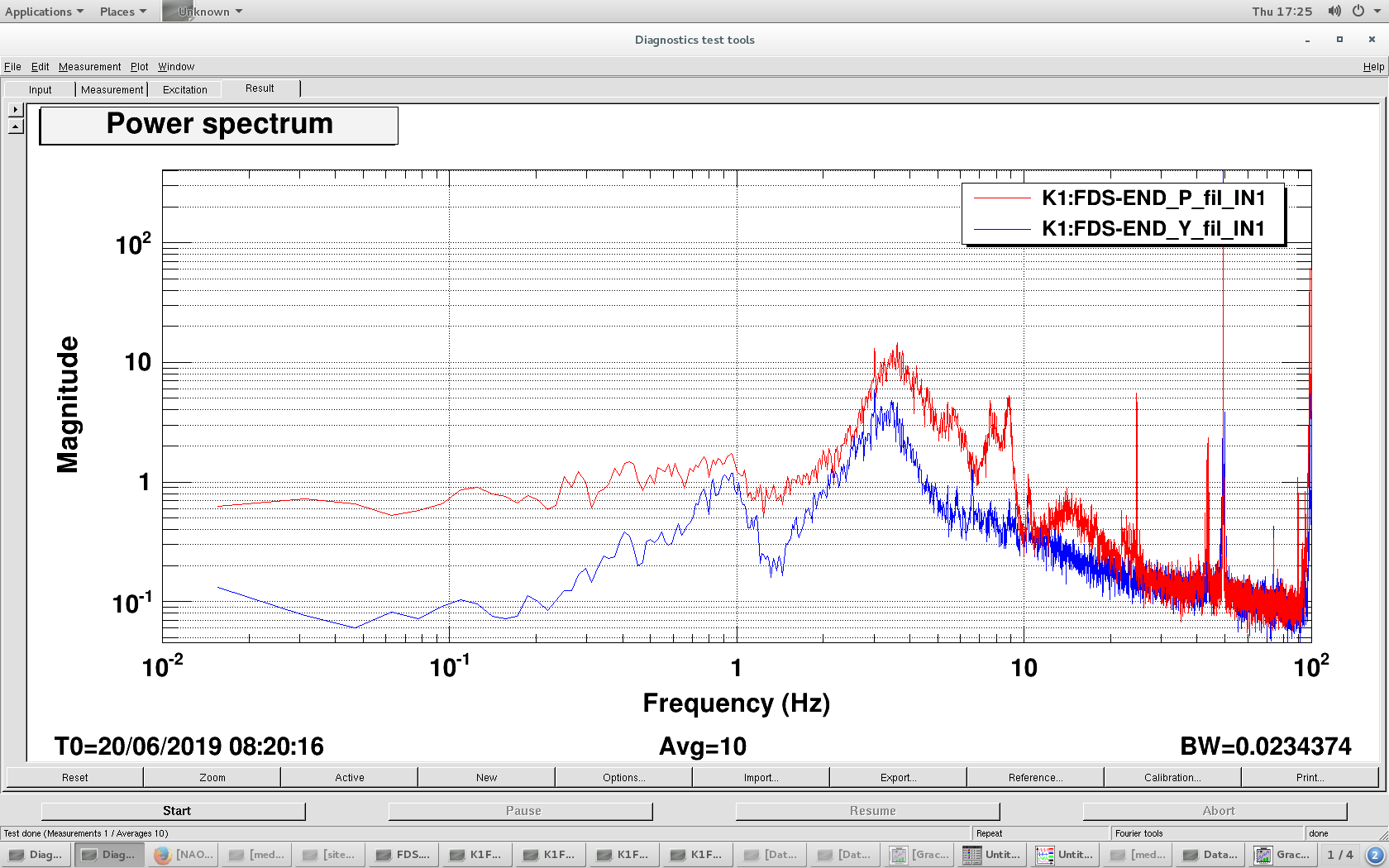
As described in the title, we characterized more about coherent control loop 1.
The dark noise is measured when there is not light. And other situation is the same(for example, PD is on, demodulation signal is on). The measurement point is error signal.
The free running error signal noise spectrum is measured after we checked that green phased shifter scanning and coherent error signal was fine.
EleonoraC, Takahashi, Yuhang
Today we have power outrage in TAMA, we switched off the vacuum system and air compressor yesterday. The procedure is similar to entry 1138. The list of things we did is summarized in the attached pdf file.
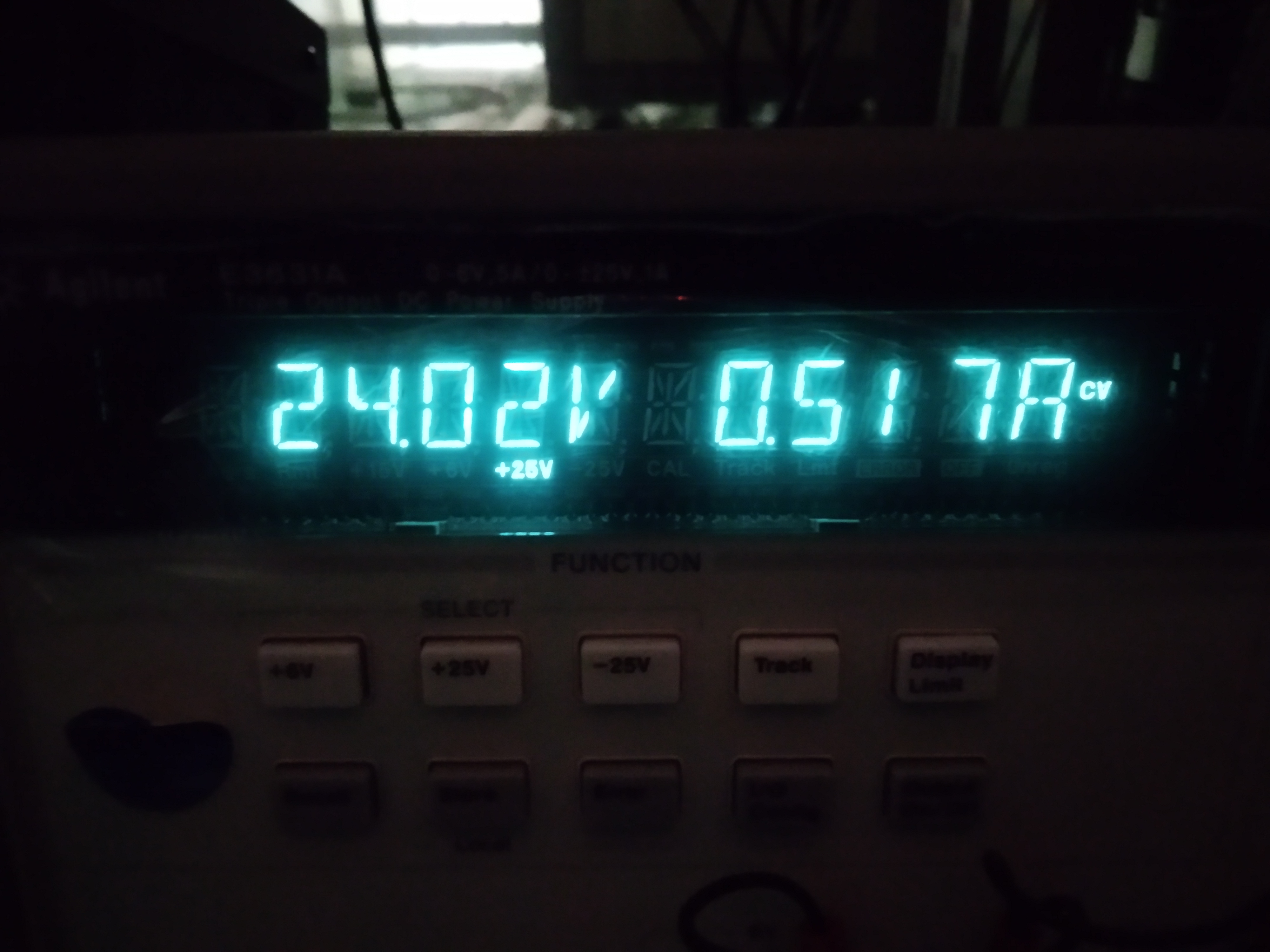
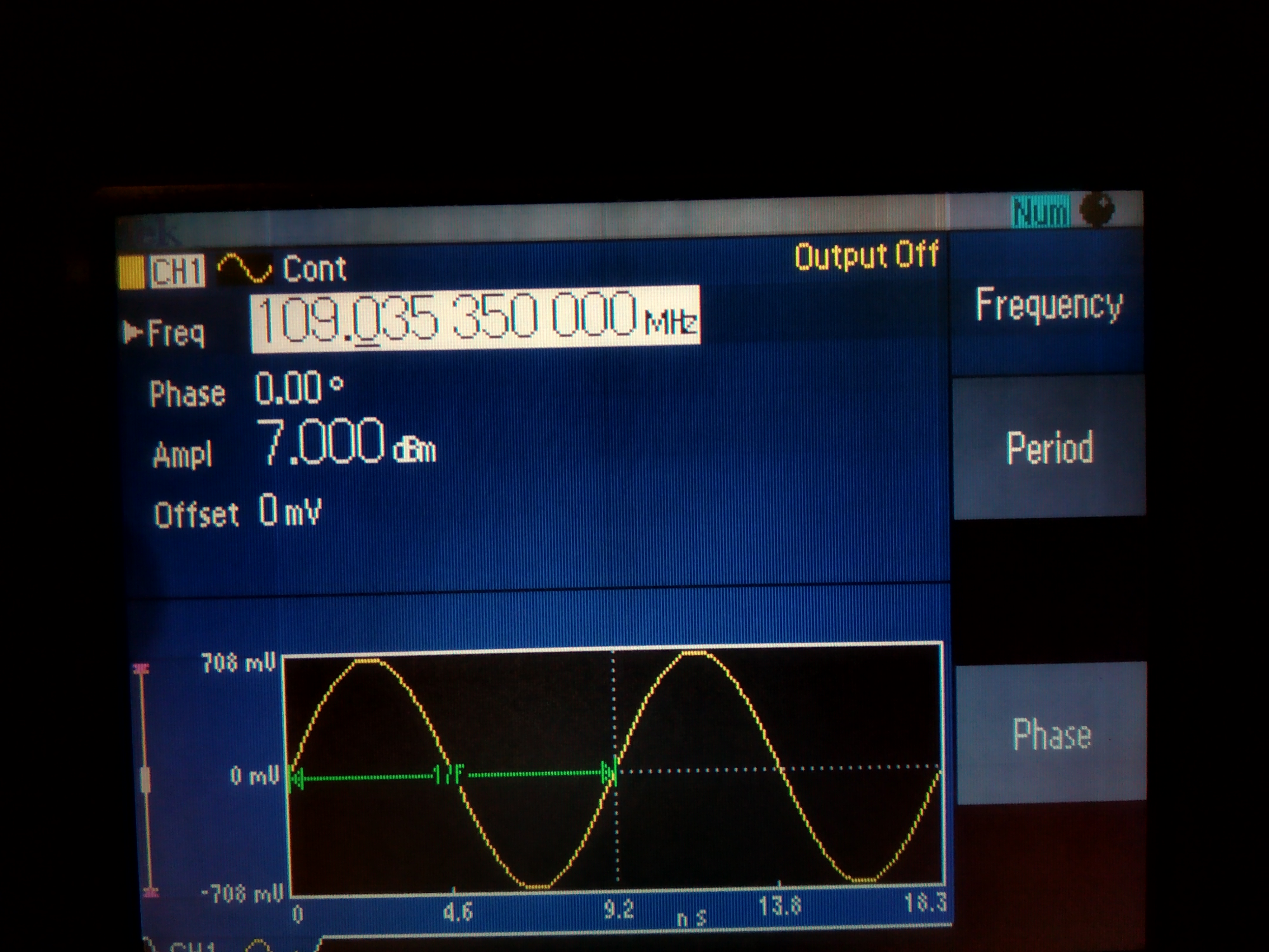
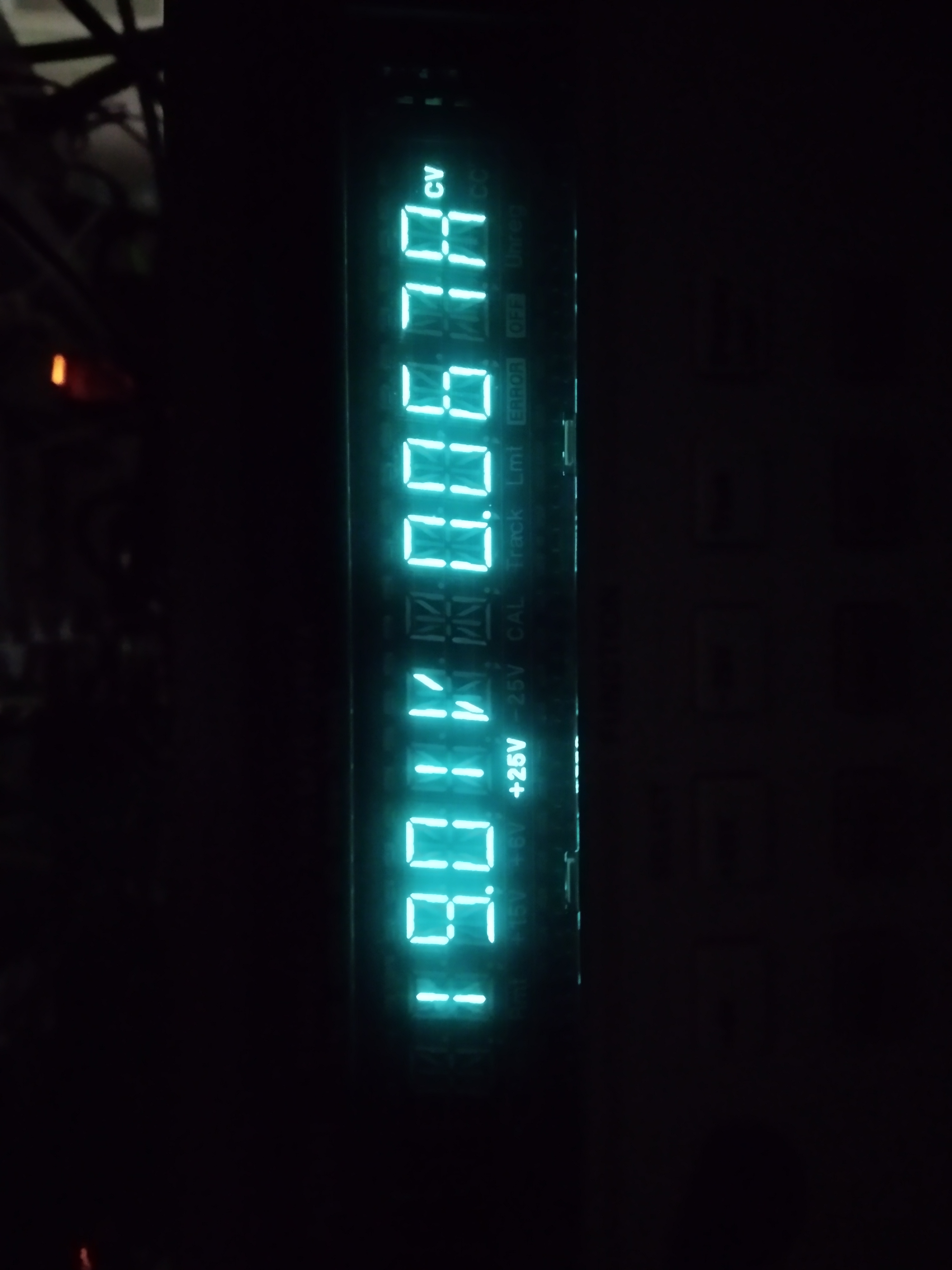
Here I also attached some numbers we need to recover later.
| power supply for AOM RF amplifier | 24V |
| RF driving frequency for AOM | 109.03535MHz 7dBm |
| power supply for homodyne | 19V |
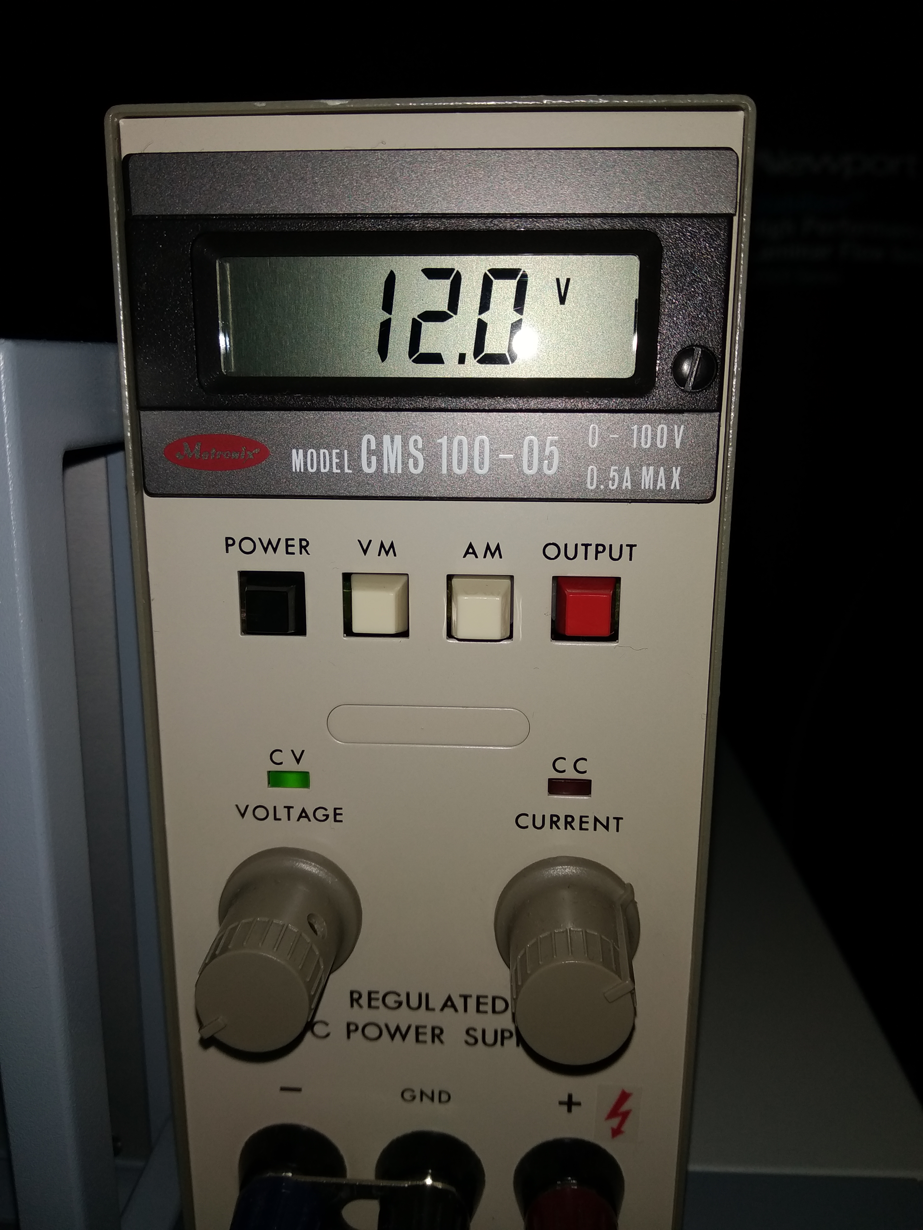
| power supply for TAMA PD | 12V |
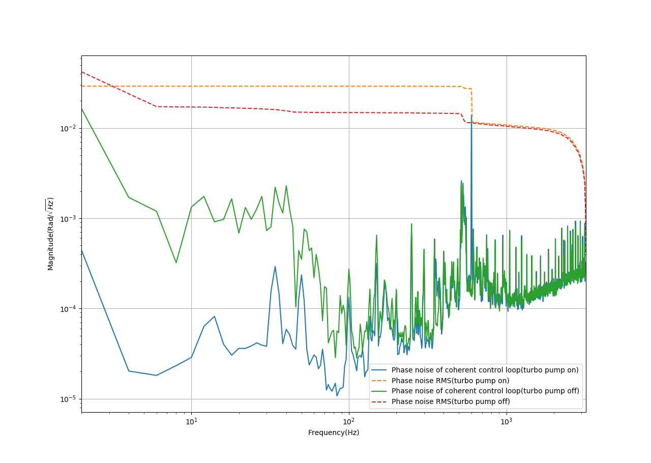
After the implementation of CC1 mirror mount, we used the 1/f integrator and locked this loop(with unity gain frequency of ~2.2kHz). We measured open loop transfer function and the noise spectrum of the error signal. The result is as follows.
But the measurement of the noise spectrum when the turbopump was on/off was not so reasonable.
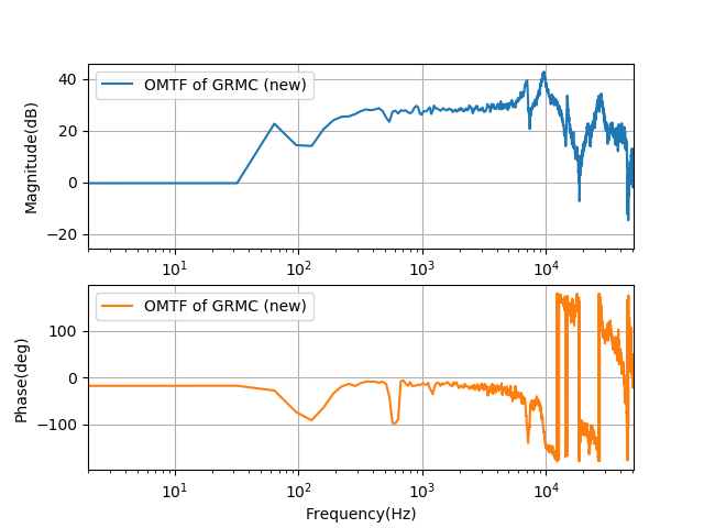
We decide to characterize this loop again. Including the measurement of free-running noise, noise while locking, PD dark noise and also the optomechanical transfer function.
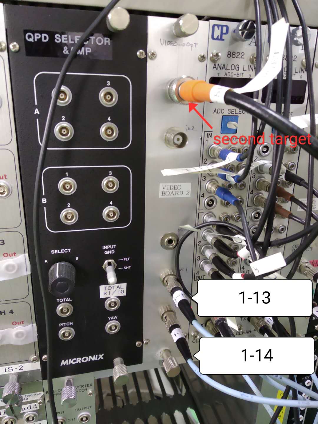
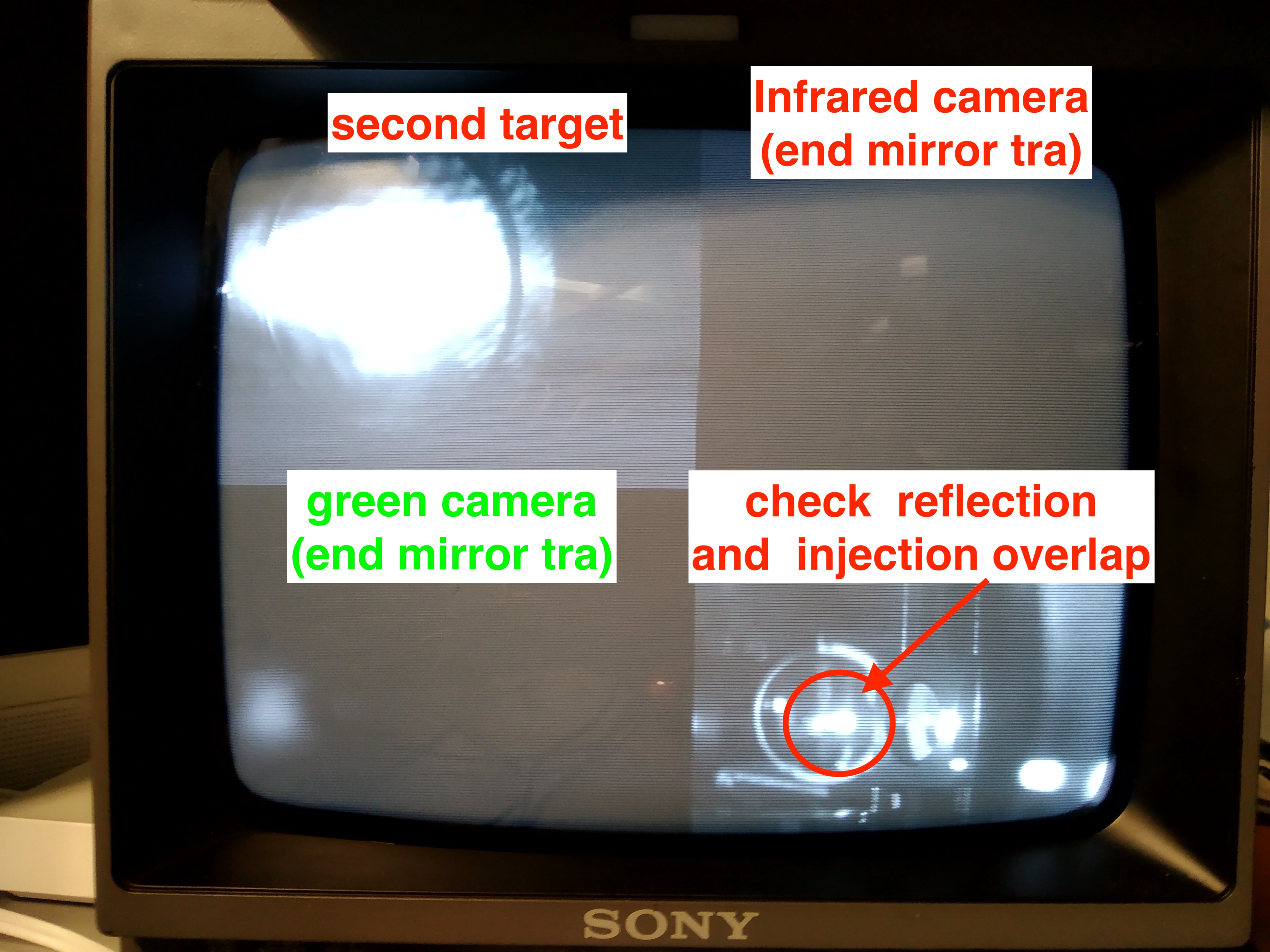
We always need many people to check several checking points to align the filter cavity. Also, the channels for monitoring video signals from the end room were not enough(two channels were working at that time).
This means: (1) camera is not enough (2) channels are not enough
- For the camera, we set up a new camera to take real-time video inside PR chamber. By using this camera, we could check the overlap of injection/reflection beam.
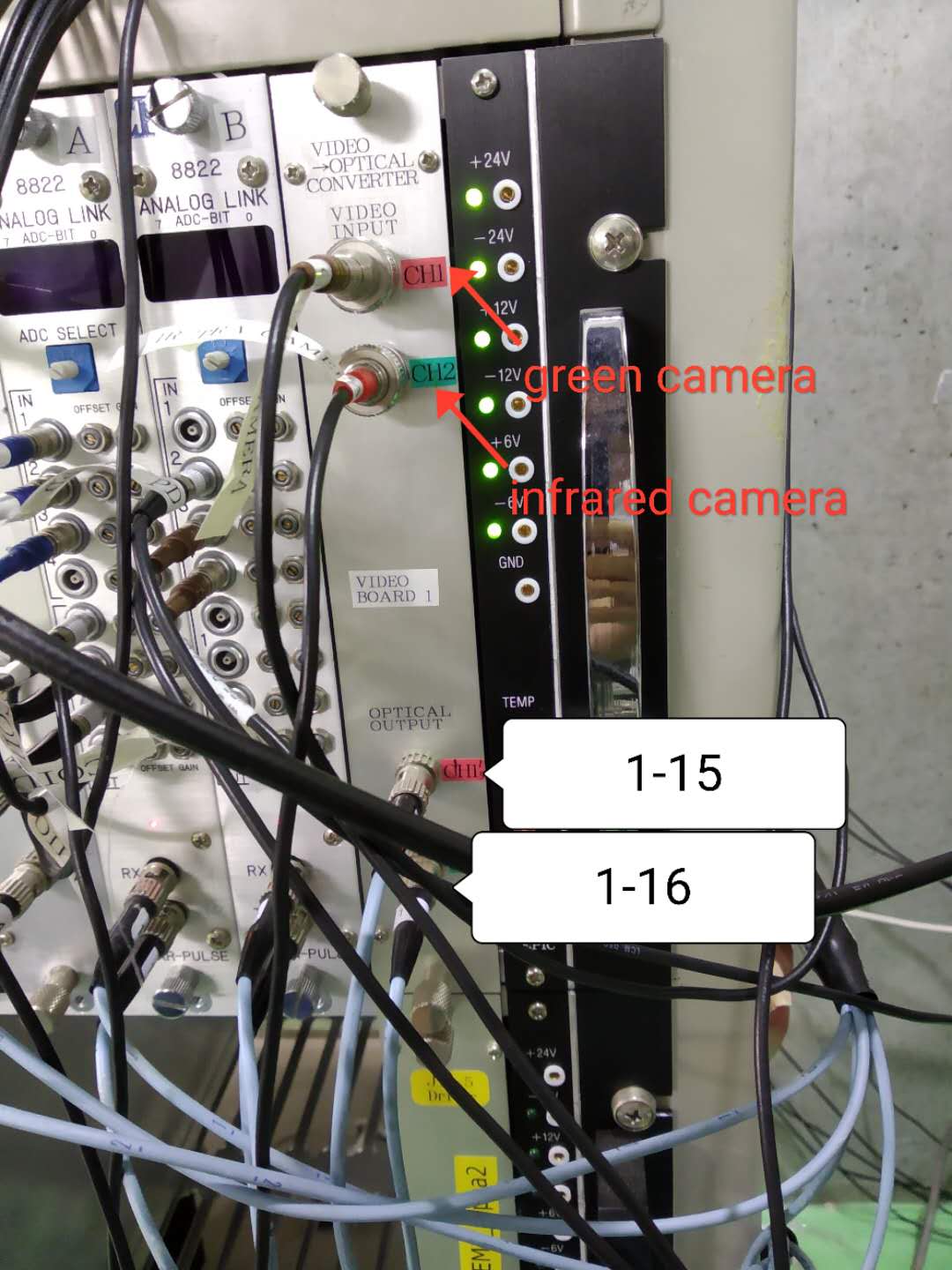
- For the not enough channels, we found two cables(actually is fiber) were broken from west-south corner to control area(we can also call it 'short part' of fiber). We replaced them(Broken fibers are 1-13 and 1-14. 1-13 was replaced with a working fiber and the label was changed as well. Now the 3-11 short part is broken). Then we found one of the channels of board1 was broken after one-day work. We changed it to a good channel later.
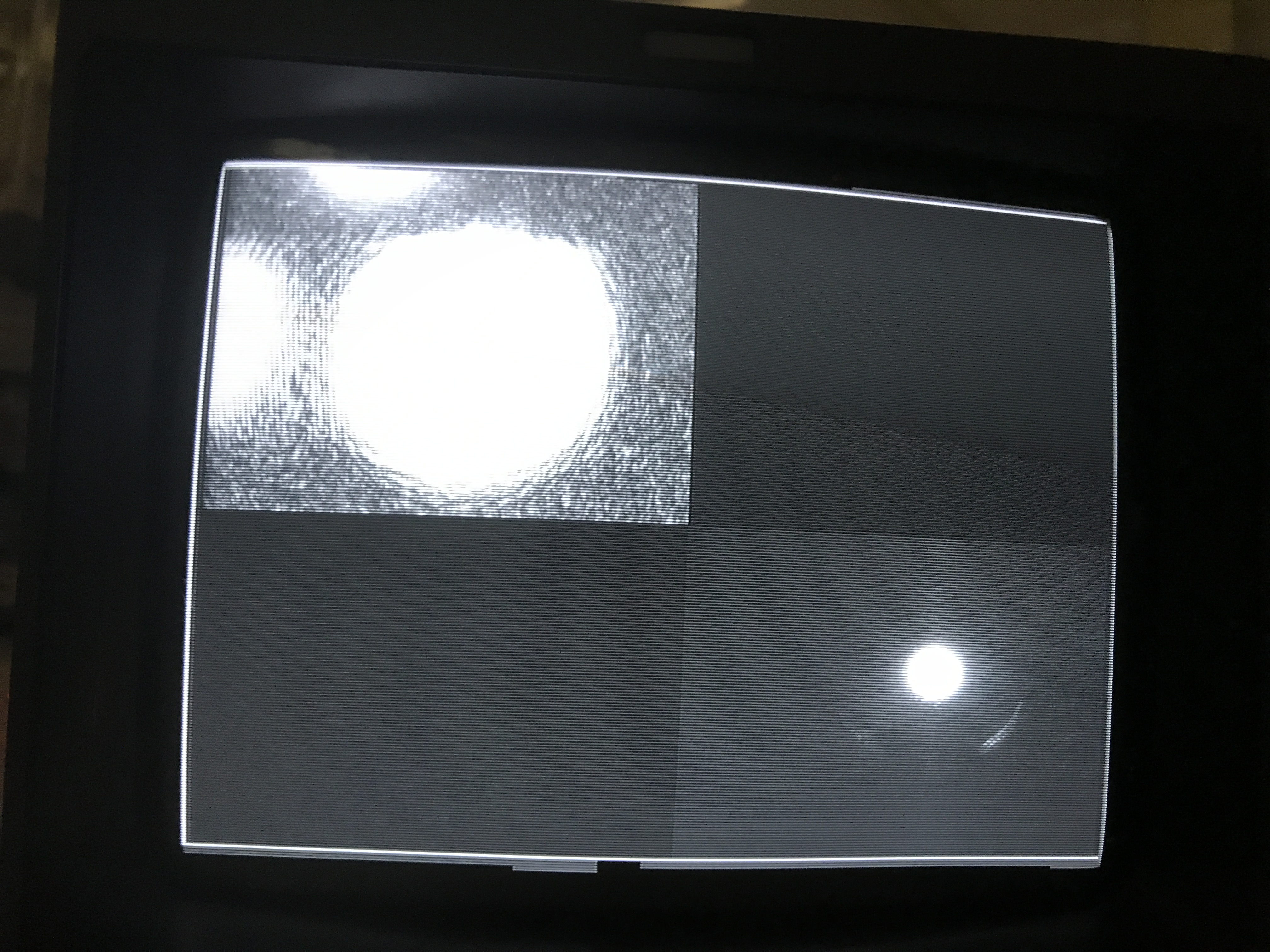
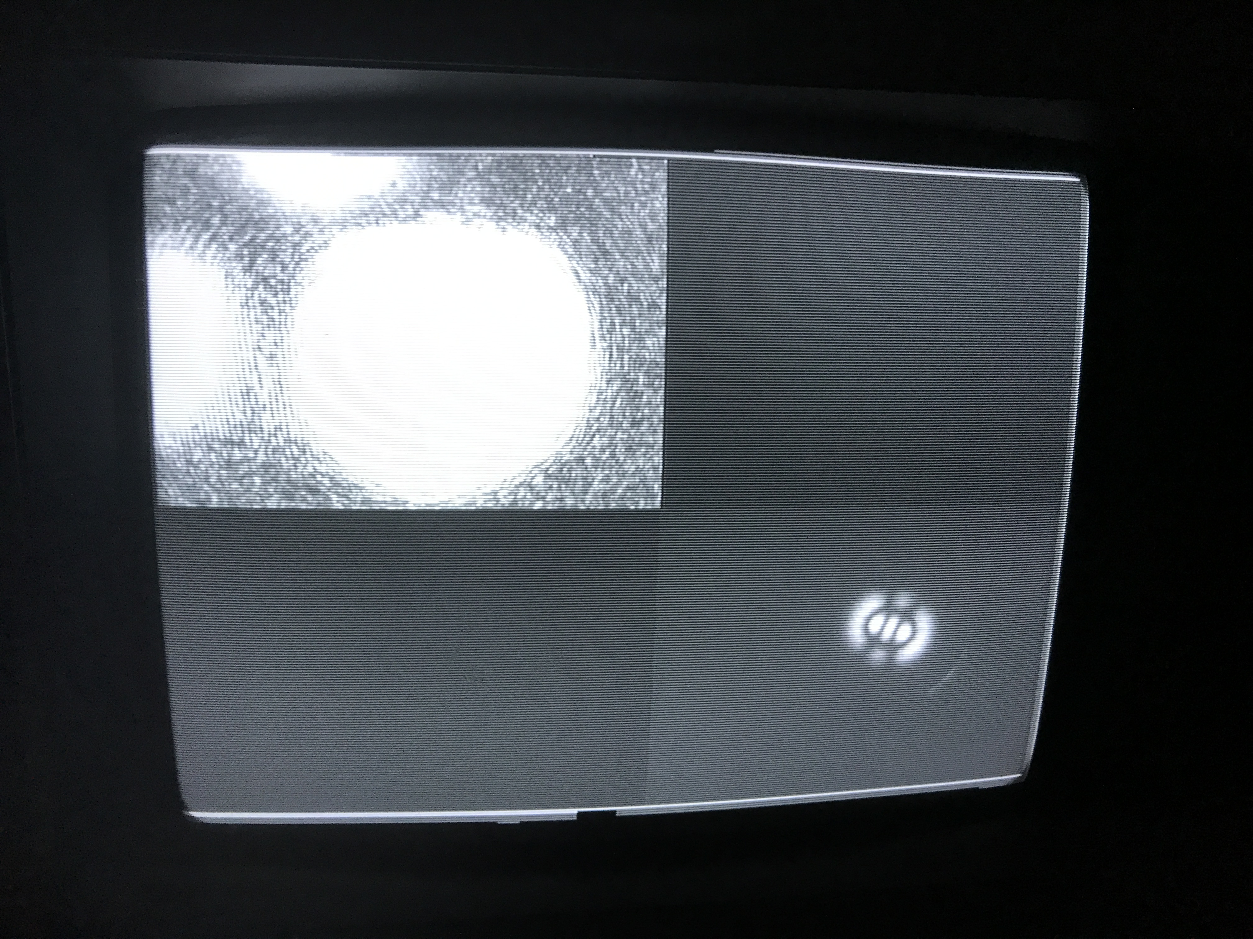
In the end, we have four real-time videos on the screen and an additional one (first target) which can be monitored after we switch from channel A to channel B. The organization of four videos are as follows
| Second target | infrared camera(FC Tra) |
| green camera(FC Tra) | monitor inside PR chamber |
The connection situation at the end room is shown in the attached figure 1 and 2.
[Eleonora, Matteo]
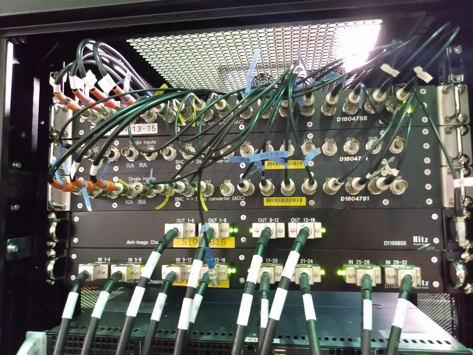
Up to now we have been using only 16 of the 32 channels available in the ADC of the standalone DGS recently installed in TAMA.
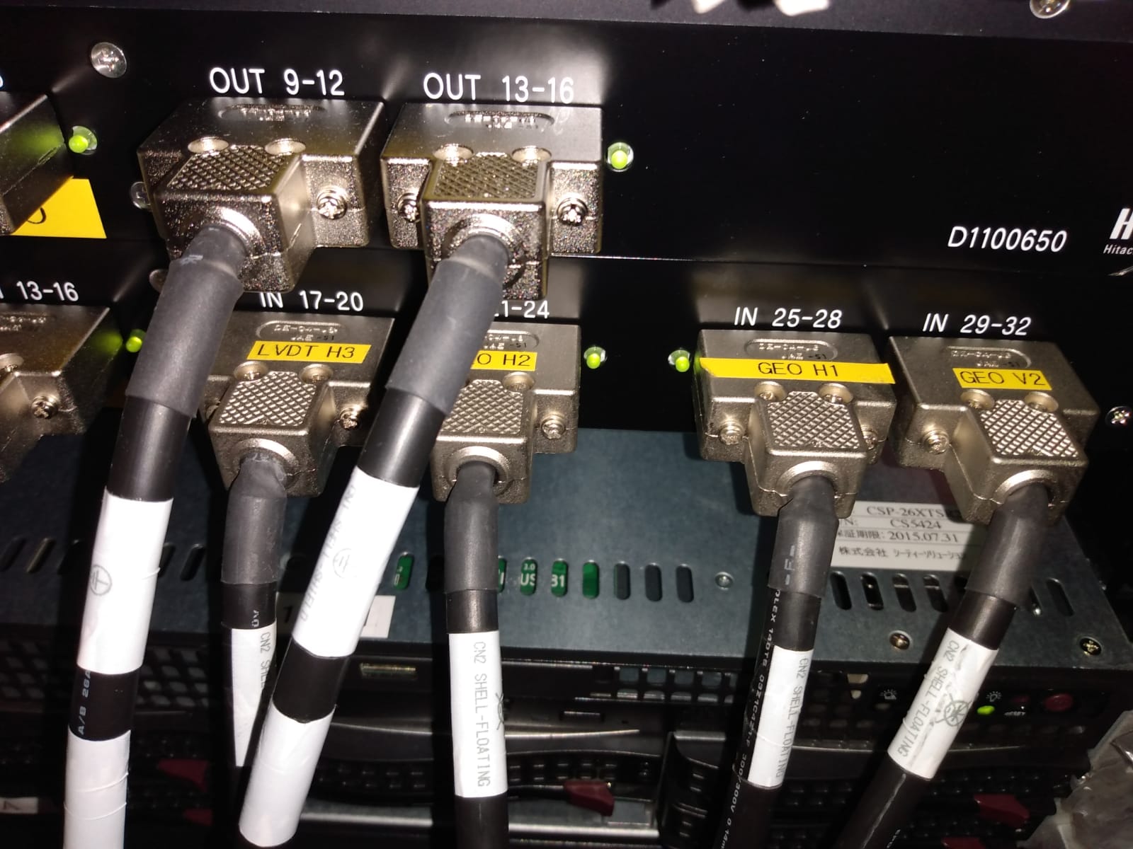
Today we received from Kamioka the BNC->Dsub converter that we missed in order to use them all. We have installed it and connect 4 more cables from the AA to the converter (each of them as 4 channels) (pic1).
We borrow these 4 cables from ATC after asking Akutsu-san (pic 2). The cables are much longer than what we need (pic3) so in the future it would be good to change them with shorter ones.
I have modified the realtime model to include these additional channels and I verified that it is working fine.
In conclusion, we have now 32 ADC channels in our DGS.
According to Emil's thesis P. 42 figure 2.10 or P.48 figure 2.13 (b), 200 mrad of phase noise seems to degrade 15 dB of squeezing to almost 0 dB of squeezing. Our situation seems around 100 mrad of phase noise. Did you consider the effect of control bandwidth when you calculated rms phase noise? As you noted, it's better to measure the spectrum and integrate it within control bandwidth.
[Aritomi, Eleonora P]
You are right. We'll scan AOM frequency in the range of 1MHz.
It is expected that you don't find a TEM00 each 0.5 MHz frequency shift. As reported in entry #661, since the AOM is put on the green path, the change in the frequency which it induces is compensated by the servo with a change on the IR which is half of the frequency change in the AOM. This means that a shift of 1 MHz in the driving frequency of the AOM corresponds to a shift of 500 kHz in the frequency of the IR light.
I think that we can now start to tweak the lens position to improve the matching. It would be also good to do a cavity scan as the one done in entry #776.
[Aritomi, Eleonora P]
Today we managed to align IR into filter cavity and lock both green and IR again. First we locked IR with 109.03569MHz of AOM frequency as last measurement, but we found that TEM00 is much brighter at 109.03535MHz (Pic 1).
The power of each mode is as follows. Pic 2-7 shows shape of each mode other than HG10. Since green phase lock is not stable, we scanned green phase and measured maximum and minimum of IR transmission. Green phase is scanned at 20Hz.
| AOM frequency (MHz) | Transmission power (mV) | Mode |
| 108.62391 | 55.2 - 84 | |
| 108.62430 | 55.2 - 88.2 | |
| 108.81421 | 55.2 | |
| 108.82913 | 58 - 198 | IG20 |
| 109.02021 | 60.8 | |
| 109.02083 | 60.8 | |
| 109.03535 | 64 - 608 | TEM00 |
| 109.43143 | 54 - 144 | HG10 |
| DC offset | 45.6 |
Now largest mode is TEM00 and main higher order modes are IG20 (Pic 5) and HG10.
It is expected that you don't find a TEM00 each 0.5 MHz frequency shift. As reported in entry #661, since the AOM is put on the green path, the change in the frequency which it induces is compensated by the servo with a change on the IR which is half of the frequency change in the AOM. This means that a shift of 1 MHz in the driving frequency of the AOM corresponds to a shift of 500 kHz in the frequency of the IR light.
I think that we can now start to tweak the lens position to improve the matching. It would be also good to do a cavity scan as the one done in entry #776.
You are right. We'll scan AOM frequency in the range of 1MHz.
I measured END oplev signal with dataviewer. The signal somehow oscillates at around 1.5Hz...
Beam spot fluctuation seems at several Hz. I measured PR and BS closed loop spectrum. This also looks fine.
Both the open loop and close loop end mirror TF look fine to me. There is no oscillation at 0.3 Hz. Note that striptool used EPIC channels are sampled at 64 Hz, so the oscillation could be an artifact (down-coversion of higher frequency noise?) You can double-check with dataviewer.
From the movie of the transmitted beam it is not clear the frequncy of the oscillation but it likely to be from a steering mirror (BS or PR). It would be useful to take a spectrum of their motion.
[Aritomi, Eleonora P]
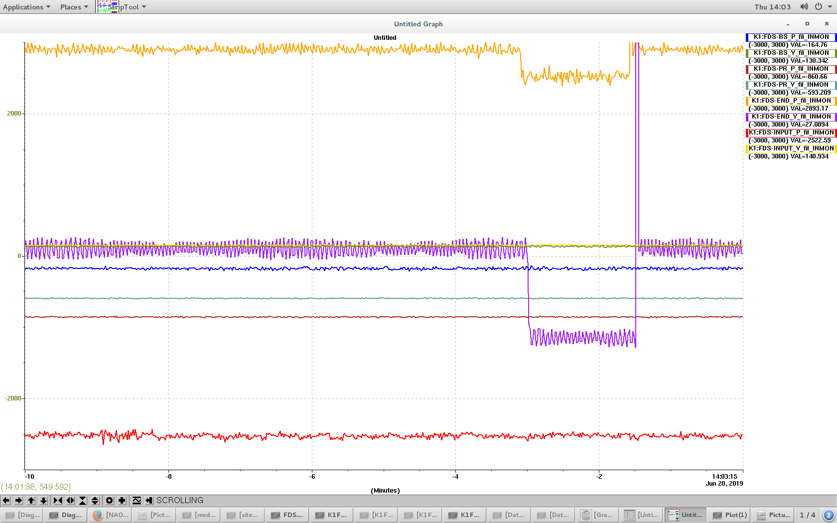
We found that green beam spot at trans is fluctuating (Mov 1) and drifting. So we measured oplev signal of each mirror. From Pic 1 we can see that END mirror is fluctuating at around 0.3Hz. We opened END mirror control loop and closed it again, but it didn't change. We also measured open and closed loop END spectrum (Pic 2,3). Open loop spectrum is similar to previous result. Anyway, since beam spot fluctuation is much faster than 0.3Hz, this is not due to END mirror fluctuation.
Mov 1 green beam spot at trans
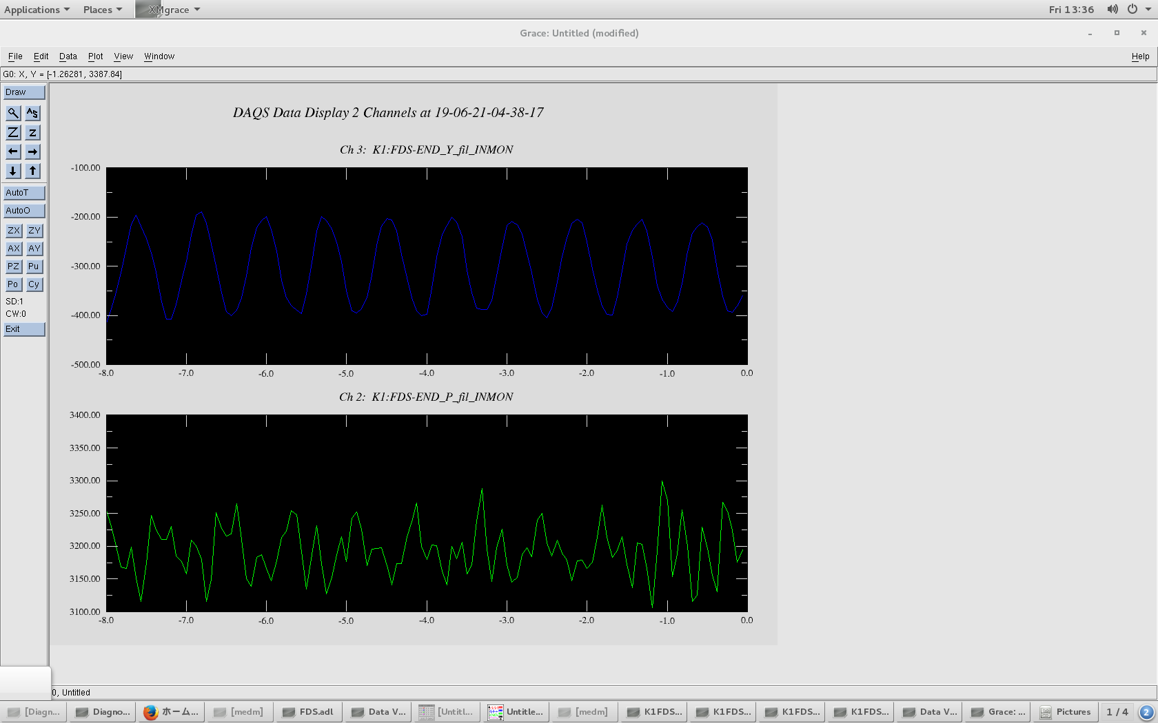
Pic 1 time series of oplev signal
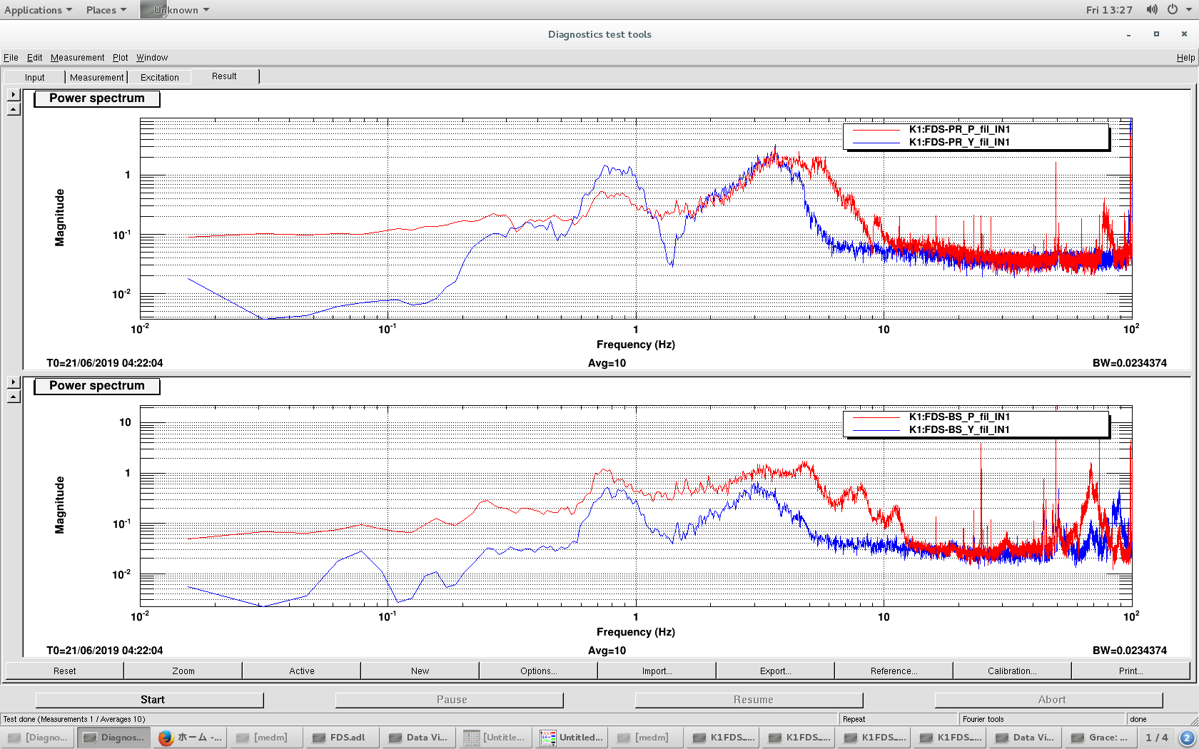
Pic 2 open loop END spectrum
Pic 3 closed loop END spectrum
Then we maximized IR reflection and could recover 00 flash once, but problem is that green alignment keeps drifting during IR alignment. Beam spot of green reflection at PR viewport is going away mainly in pitch direction and centering of trans beam by BS is also drifting. We're not sure the reason.

Both the open loop and close loop end mirror TF look fine to me. There is no oscillation at 0.3 Hz. Note that striptool used EPIC channels are sampled at 64 Hz, so the oscillation could be an artifact (down-coversion of higher frequency noise?) You can double-check with dataviewer.
From the movie of the transmitted beam it is not clear the frequncy of the oscillation but it likely to be from a steering mirror (BS or PR). It would be useful to take a spectrum of their motion.
I measured END oplev signal with dataviewer. The signal somehow oscillates at around 1.5Hz...
Beam spot fluctuation seems at several Hz. I measured PR and BS closed loop spectrum. This also looks fine.
[Aritomi, Eleonora P]
Today we tried to improve the alignment of IR to filter cavity with last two steering mirrors on the bench, but unfortunately we lost TEM00 flash. We recovered the reference on PR chamber, but we couldn't find 00 flash (we didn't maximize IR reflection and check second target). Tomorrow we'll maximize IR reflection and try to recover 00 flash and improve the alignment.
[Aritomi, Eleonora P]
When we changed gain of filter cavity lock, glitch appeared in GRMC transmission and variable gain out of MZ like an attached picture and GRMC and MZ lost lock.