NAOJ GW Elog Logbook 3.2

Eleonora, Pierre, Aritomi, Yuhang
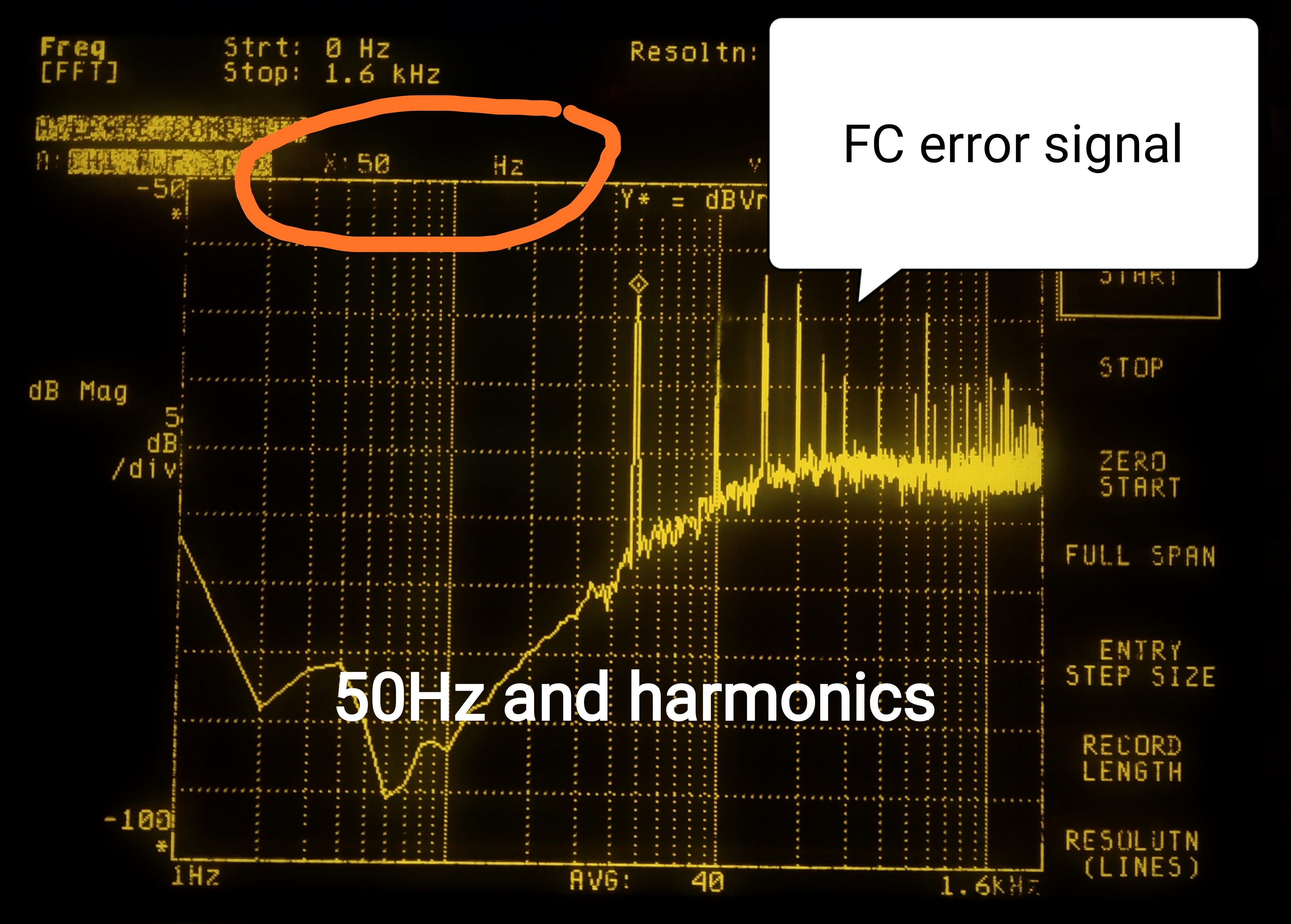
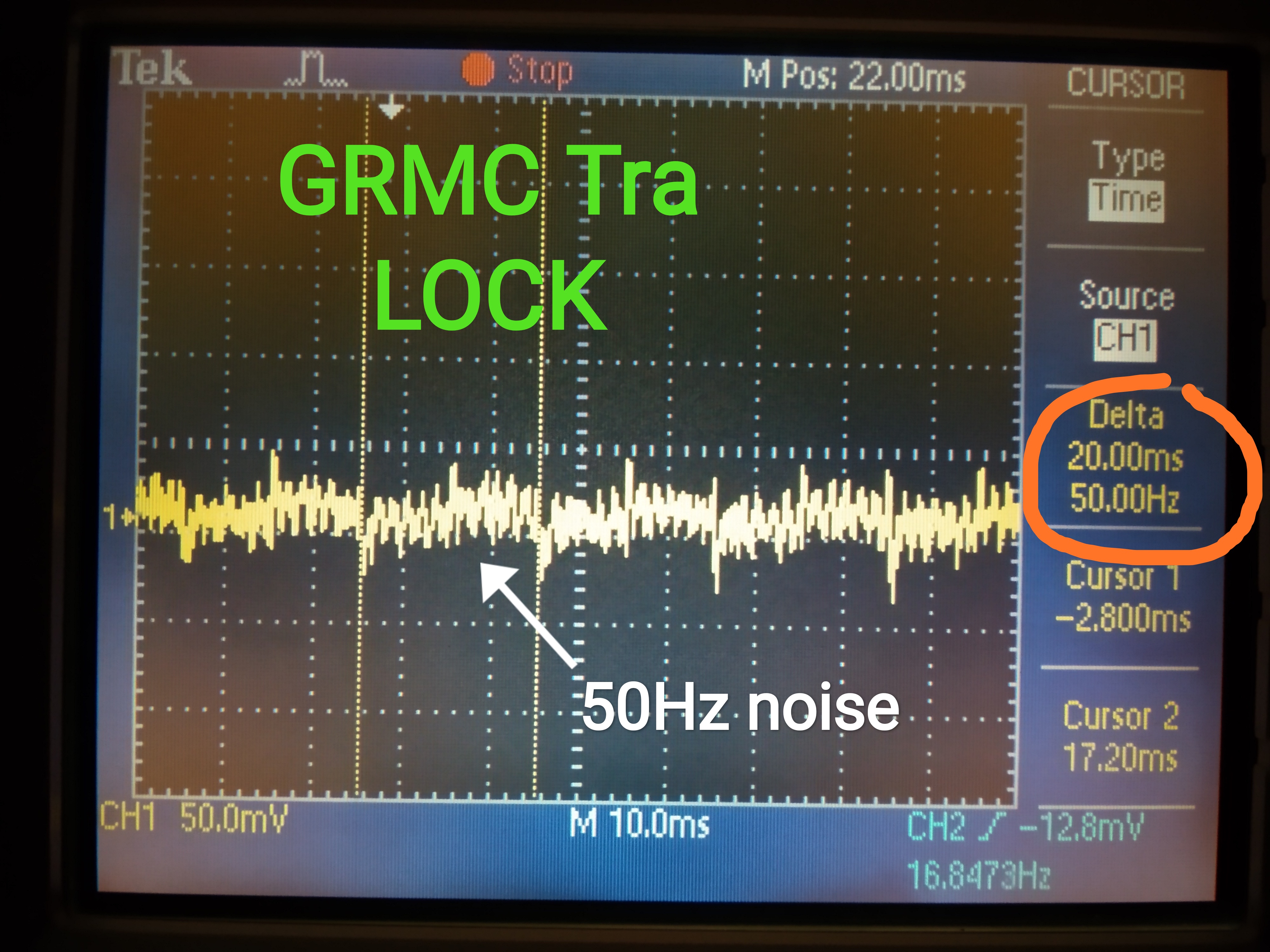
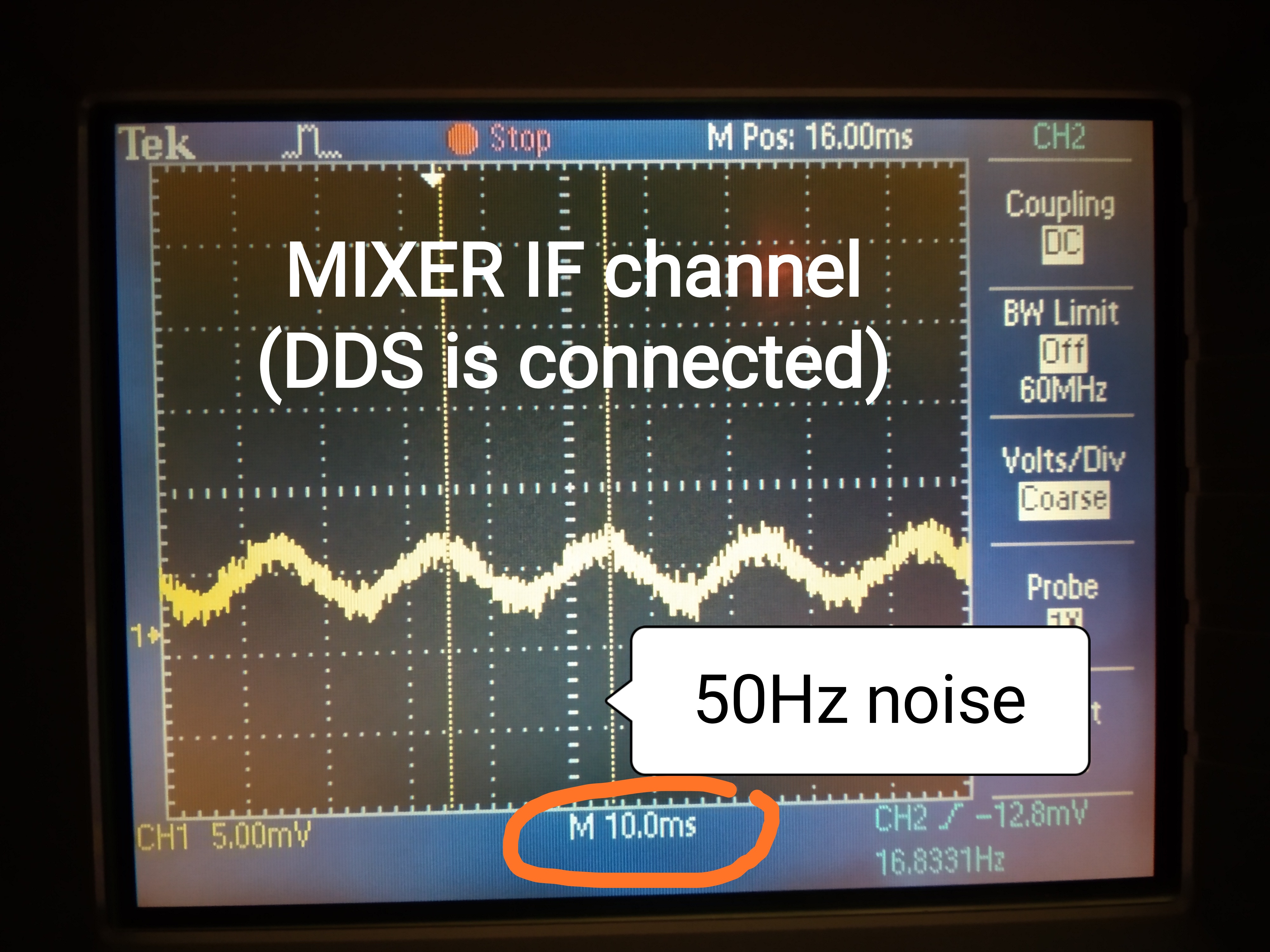
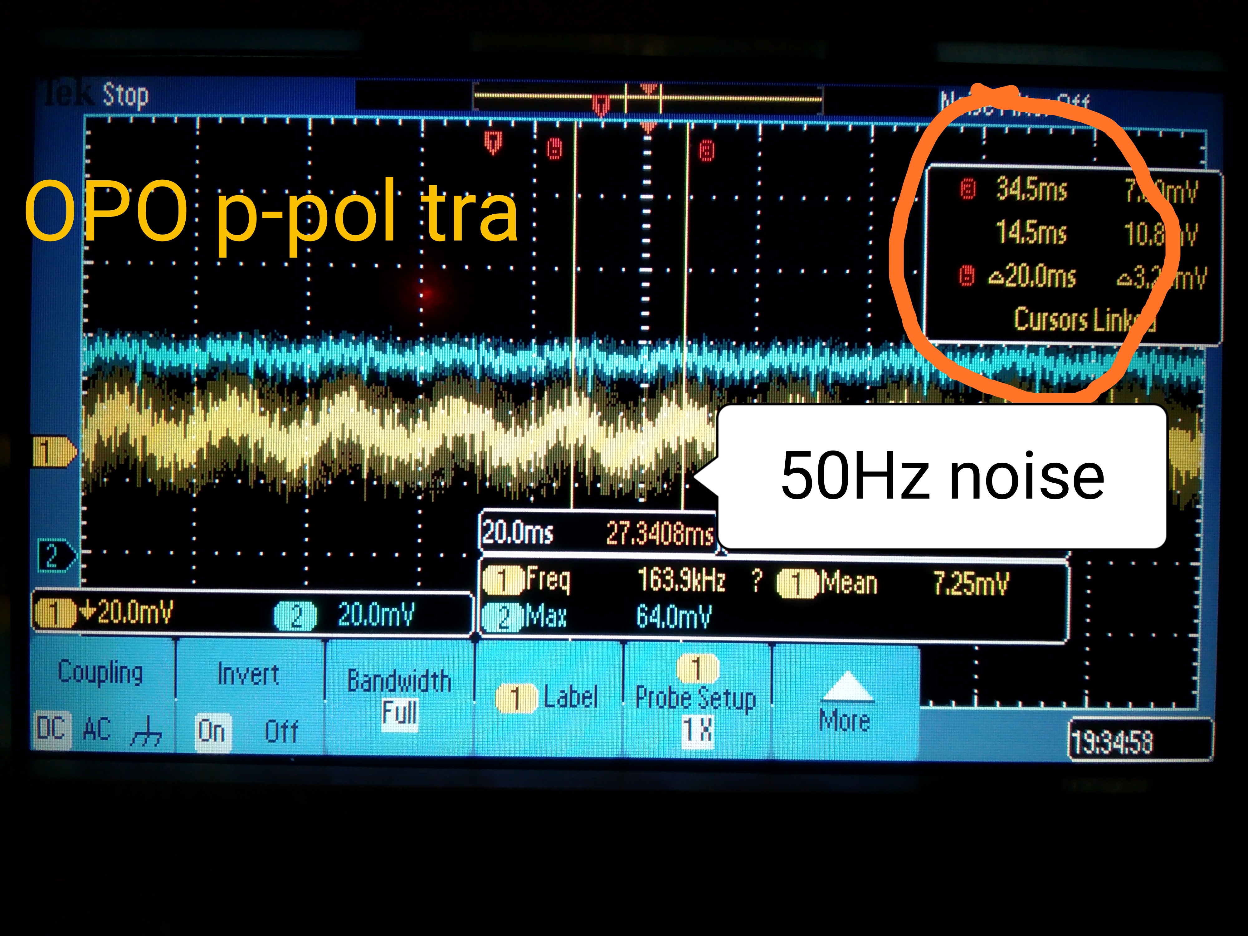
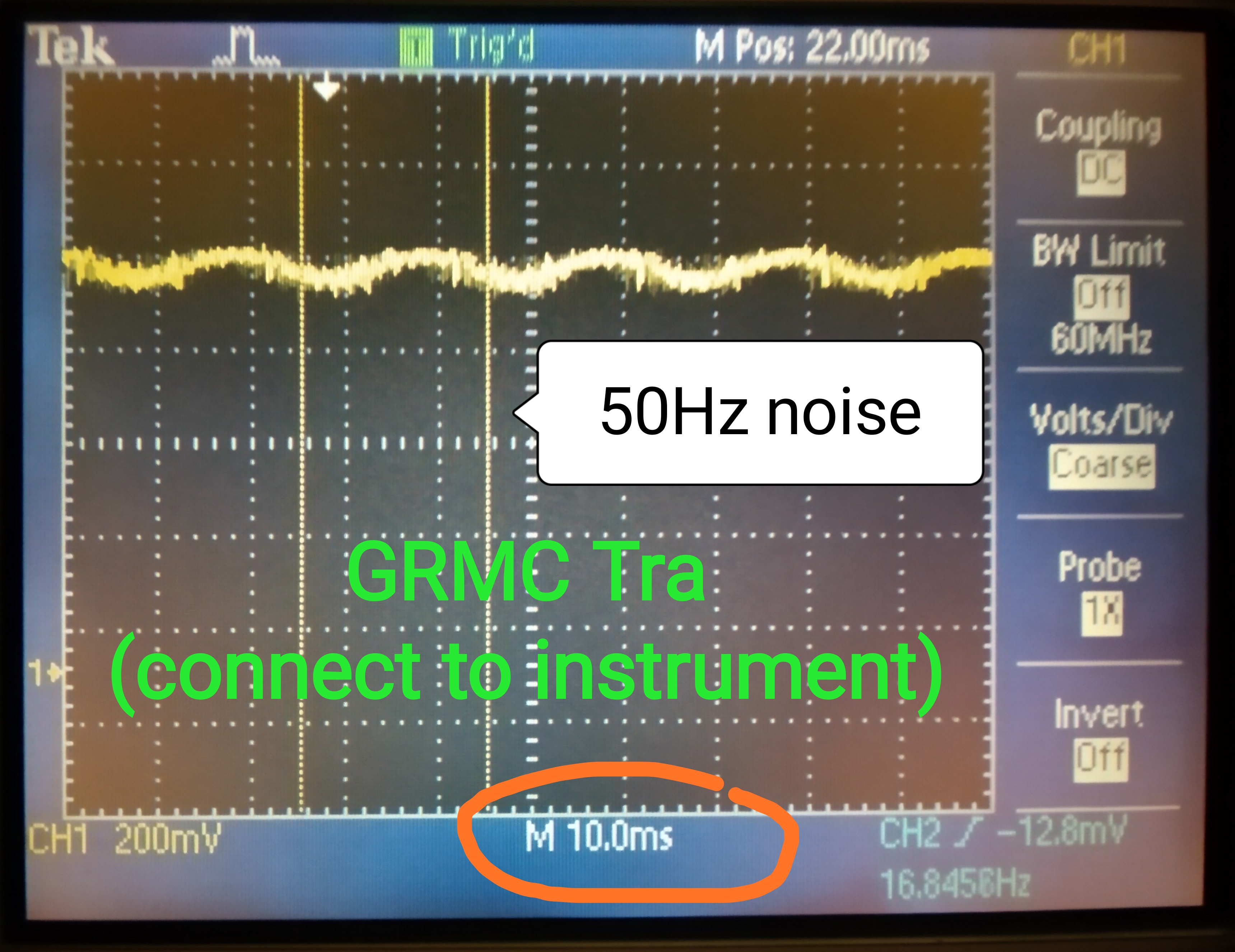
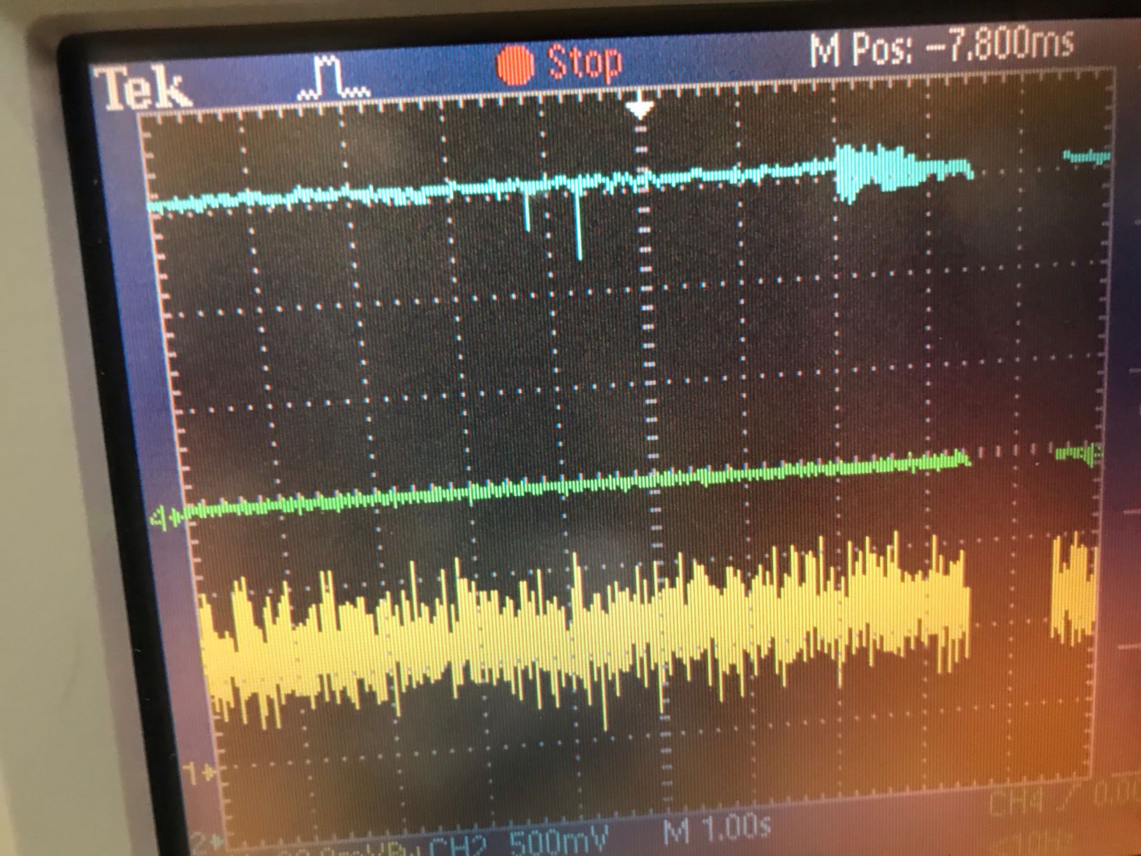
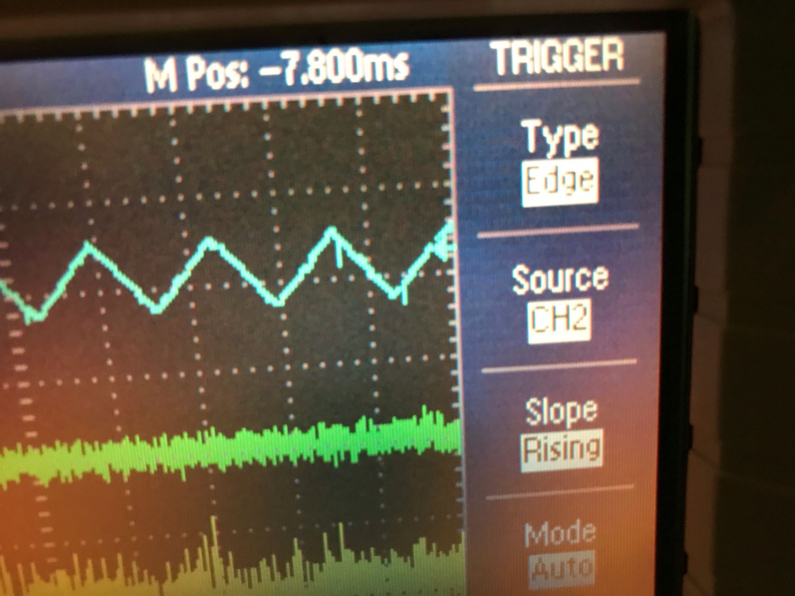
Recently we found 50 Hz presents everywhere. In the attached figures, we can see some examples of these 50Hz noises.
A part of noise level was identified that it comes from of ground loop between circuit and measurement device. This is identified by changing the power supply of the oscilloscope to different places. But we cannot eliminate this noise totally. (From figure 5 to figure 2, the change is the change of oscilloscope power supply)
We also identified that the 50Hz noise for GRMC transmission signal comes from the DDS board. At that moment, only DDS board output is connected to mixer and mixer IF channel is connected to the oscilloscope. We tried to change the connection with and without a lot of other components, and we found only DDS board gives this 50Hz noise. (Figure 3)
We see a different shape with normal measurement 50Hz noise for GRMC transmission signal, so we think this noise coupled into control loop and affects the phase locking of GRMC a lot. (Figure 2)
Pierre, Yuhang
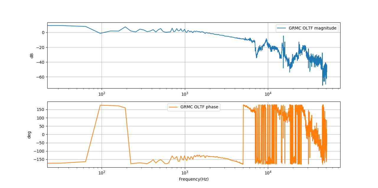
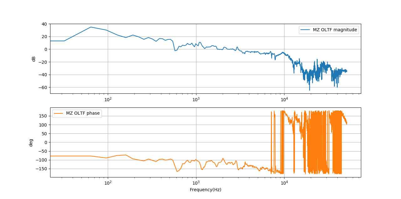
After the design/talk/discuss with Matteo, Eleonora and us, Pierre redesign the circuit and we implemented it. Now the procedure is just to press 'reset' button and then MZ and GRMC will be locked in sequence. Please also remember to use 'auto' mode of GRMC and 'man' mode of MZ and put them both in 'lock' state.
Then we measured the open loop transfer function of MZ.
[Matteo, Simon]
Today we switched on the 1064nm pump laser for the first time after four months. We had some problem identifying the correct COM port (COM11) but solved that the laser could be successfully switched on and controlled from the PCI computer. One thing to be noticed is that the power cord of the pump laser seems to have connection instabilities, please remember to be careful and never touch the plug in into the power supply.
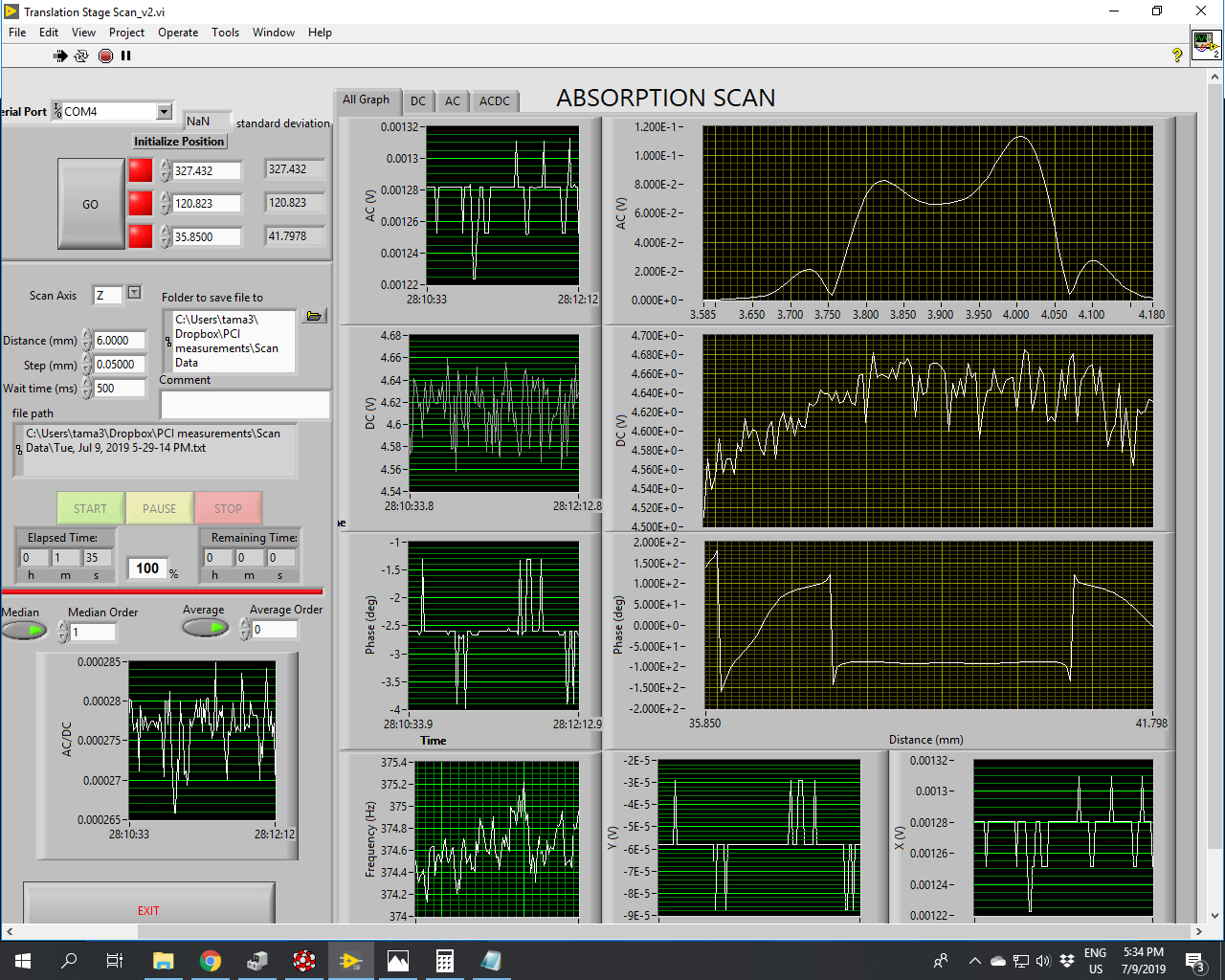
After the successful result on the pump laser we switched on the probe laser (633nm). No problems on that. We had to install a variable OD filter in front of the probe laser not to saturate the photodiode on the imaging unit. We aligned the probe on the imaging unit without any reference sample to have about 4V of DC output as read by the lock in. We then installed the surface reference sample and performed some z scan. NOTE: the written part present on the sample is facing the imaging unit. At this stage we aligned again the probe beam into the imaging unit photodiode maximizing the DC to compensate for the misalignment introduced by the reference sample, we then aligned the pump beam to maximize the AC signal at the crossing point.
MEMO: to align the probe on the IU photodiode we used the IU lens translation stage; to align the IR beam we used the translation stage on the last lens before the sample area.
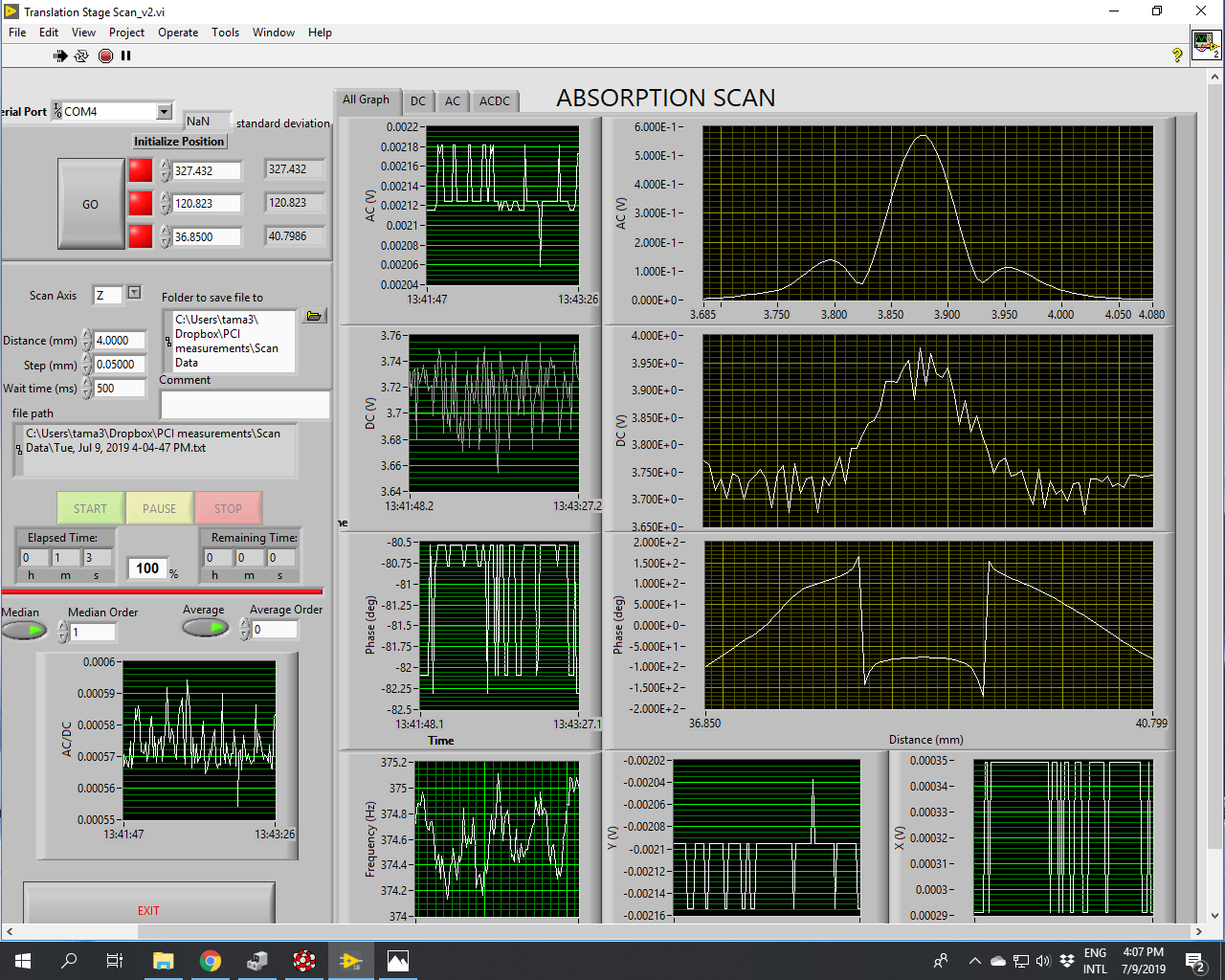
Attached (1) the screenshot of the absorption measurement for surface reference sample (try one).
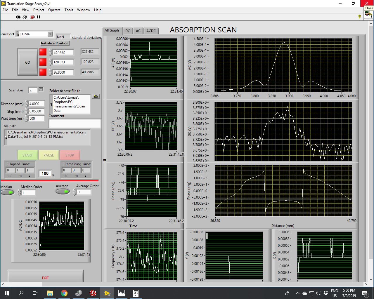
After speaking with Manuel, he told us that the written part of the surface reference sample should be facing the pump side and not the IU side. We flipped the surface reference sample and optimized again the alignment and performed again the z scan. Result is in attached figure (2).
In the end we substituted the surface reference sample with the bulk reference sample and measured the z scan. Result is in the attached figure (3).
From measurements shown in (2) and (3) we can obtain the calibration of the system.
R_surf = AC_surfref/(DC_surfref*P_in*abs_surfref) = 16 [1/W]
where AC_surfref = 0.42V, DC_surfref = 3.85V, P_in = 0.031W and abs_surfref = 0.22
R_bulk = AC_bulkref/(DC_bulkref*sqrt(T_bulkref)*P_in*abs_bulkref) = 0.604 [cm/W]
where AC_bulkref = 0.067V, DC_bulkref = 4.64V, T_bulkref = 0.55, P_in = 0.031W and abs_bulkref = 1.04/cm
The two calibration values are compatible with old calibrations.
[Pierre, Aritomi]
Pierre fixed RF amplifier and measured amplification factor for AOM which is 34dB. Since we should have 23dBm for AOM, RF signal before RF amplifier should be -11dBm.
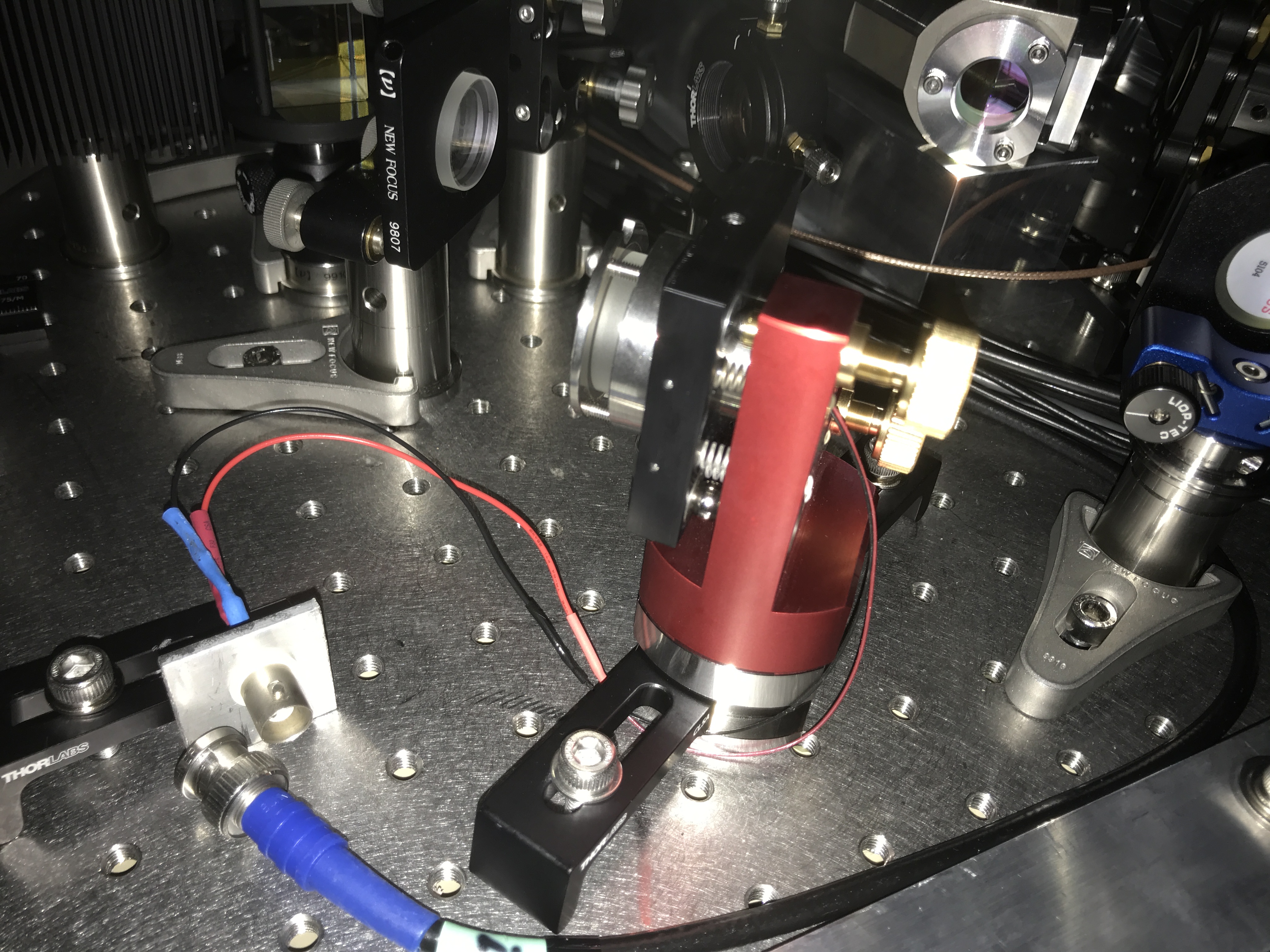
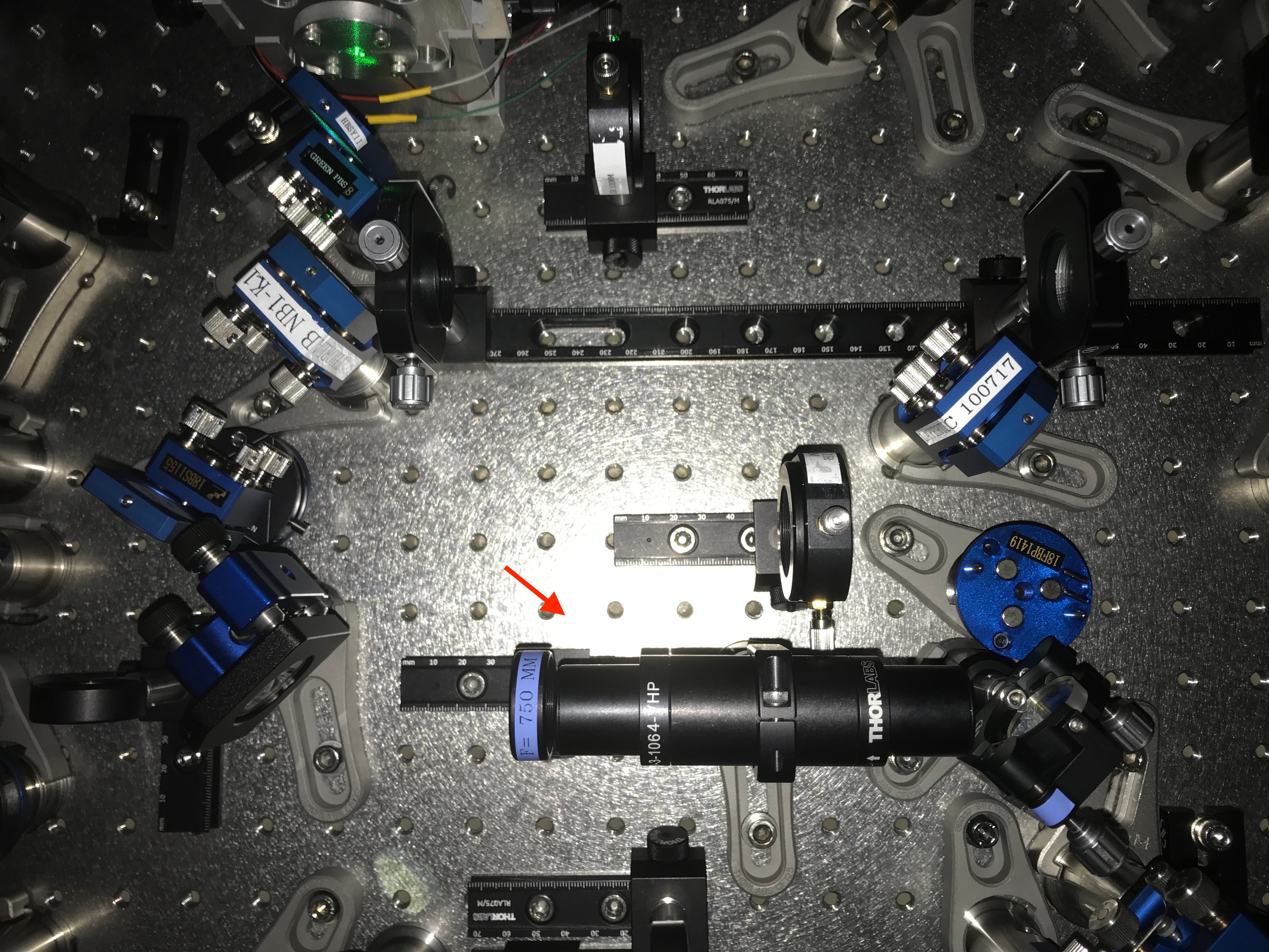
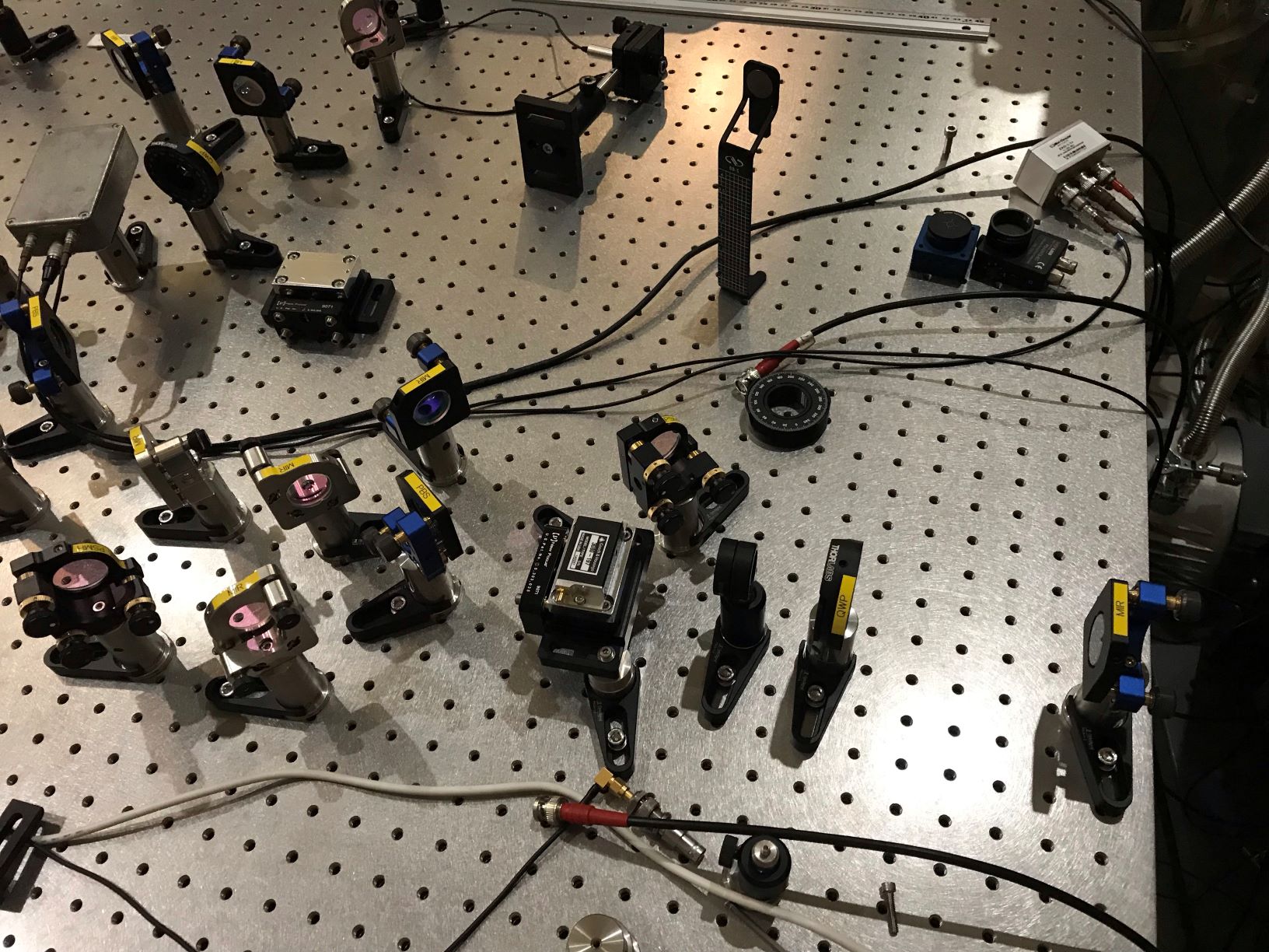
I replaced IR phase shifter with a new one (Pic 1) and aligned IRMC and locked it with Pierre's servo. Tomorrow we'll measure transfer function of CC2.
[Aritomi, Yuhang, Eleonora, Matteo]
Recently we had a problem that when BAB is injected into filter cavity, we cannot lock green phase with p pol leakage of BAB transmission. Today we found that back reflection of IR from filter cavity makes green phase error signal unstable. When we block IR injected into filter cavity, green phase error signal is stable, but when we open it and IR is aligned to filter cavity, green phase error signal fluctuates a lot. We guess that back reflection of IR from filter cavity goes back to OPO and amplified and becomes p pol leakage.
To reduce back reflection, we put faraday (IO-3-1064-VHP) after OPO on the bench (Pic 1,2). BAB transmission without green before faraday is 103mV and 100mV after faraday, which means transmissivity is 97%.
After installation of faraday, IR is totally misaligned. We'll try to align faraday tomorrow.
To connect the DGS remote desktop from cleanroom, please use Remote Desktop Connection, not Microsoft Remote Desktop. I put Remote Desktop Connection to taskbar in computer in clean room.
Matteo, Simon
We tried to start recovering the absorption bench today by reactivating the translation-stage. For this step it is necessary to reset the position of the stage, but unfortunately we got problems with this especially for the vertical axis of the stage.
After some time of an unsuccessful try and error approach, we called Manuel and tried to redo the steps he was doing usually.
In the end, we could reactivate the whole stage by tricking the Zaber console (the PC program controlling the stage) which turned out to be the main burden for a proper reset since the predefined limits for the vertical axis made it impossible reach the "home" position manually.
Actually, I added a more particular description of what we have done in the GWPO wiki: here and here
By rough estimation, the reflected power dropped ~0.3mW, though I could not see any transmitted flash.
The reflected beam power was ~3mW with 3.5V.
The dip was ~0.4V.
3mW * 0.4V / 3.5V ~ 0.3mW
The loss and high reflectivity may cause too small transmitted power.
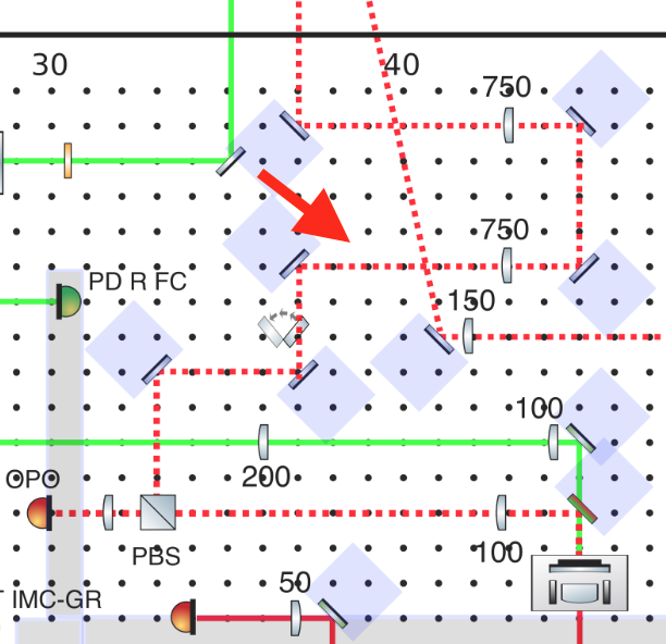
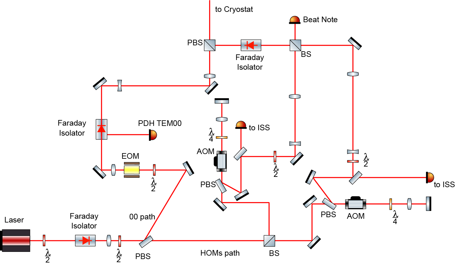
I updated the input optical layout as attached figure.
HOMs pahts are under construction now.
[Aritomi, Eleonora P&C, Yuhang]
This is work on July 5th.
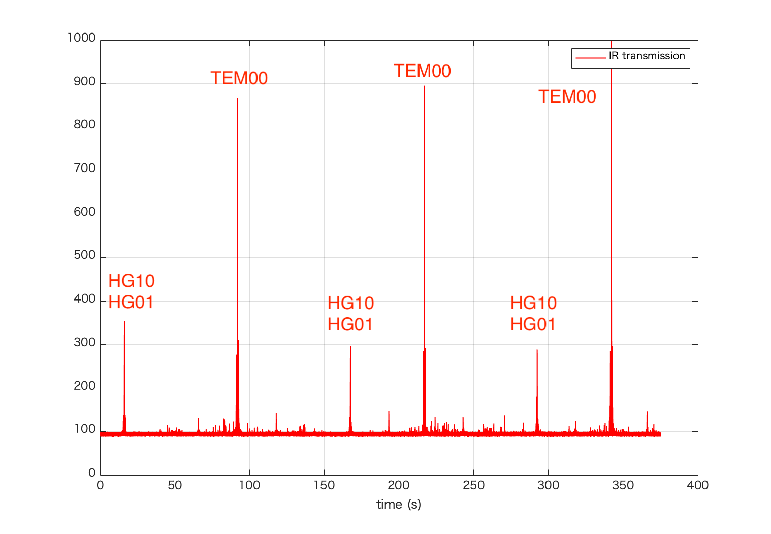
We scanned green phase at 1kHz and scanned AOM again. The result of AOM scan and TEM00 are attached. With 1kHz green phase scan, TEM00 peak isn't measured properly. After AOM scan, we locked IR on TEM00 and HG01,10 and measured each power with dataviewer.
| AOM frequency (MHz) | IR transmission | mode |
| 109.03643 | 500 - 1200 | TEM00 |
| 109.43154 | 100 - 200 | HG10 |
| 109.43199 | 150 - 400 | HG01 |
Then we tried to improve the alignment of IR. TEM00 and HG10,01 with 10 Hz green phase scan after the alignment is as follows.
| AOM frequeny (MHz) | IR transmission | mode |
| 109.03646 | 100 - 5500 | TEM00 |
| 109.43156 | 100 - 300 | HG10 |
| 109.43204 | 100 - 400 | HG01 |
We haven't measured all the higer order modes, but mode matching should be around 90% now.
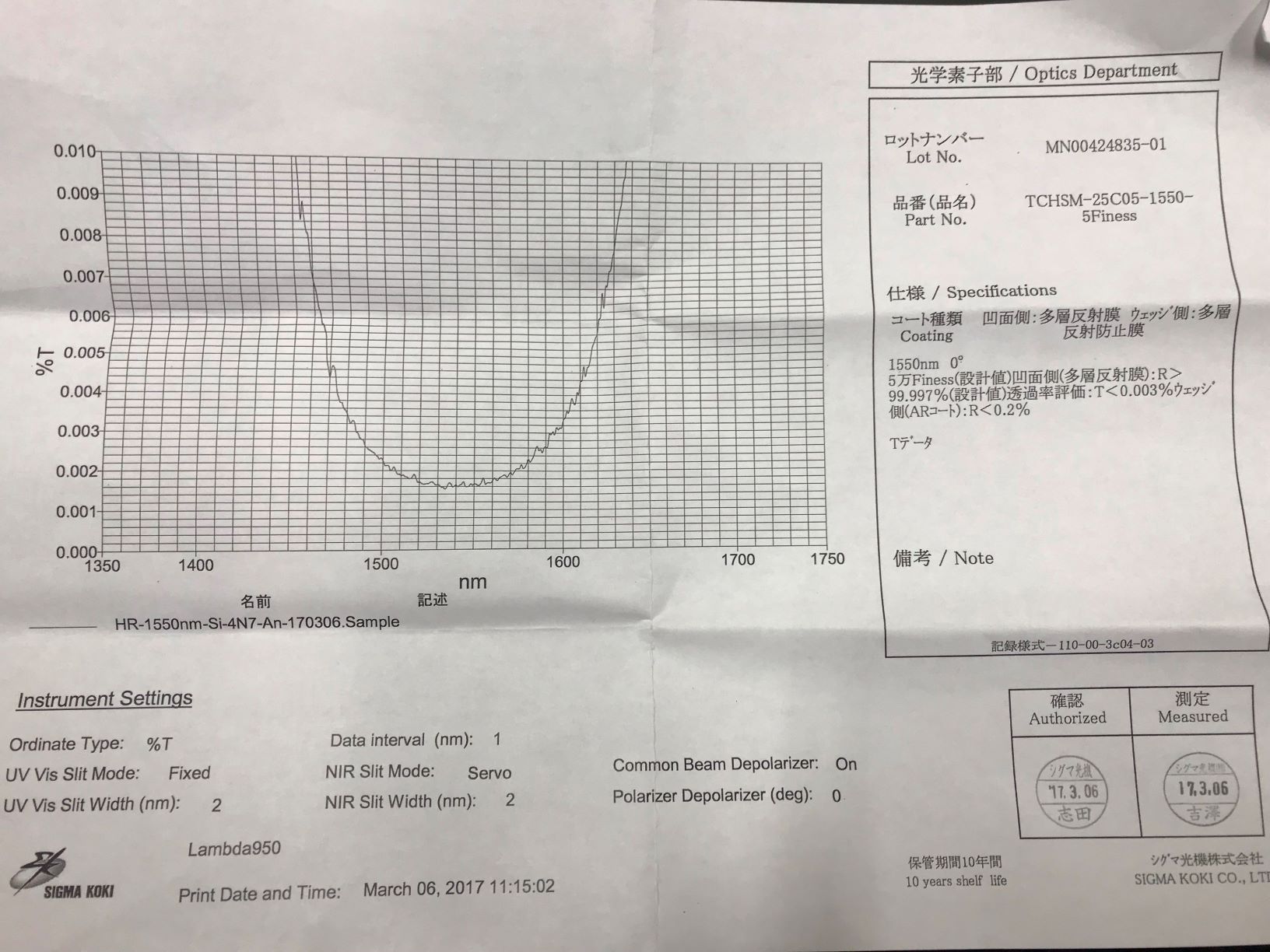
I measured the transmittance of one of the silicon mirrors using power meter.
When I injected 10mW power laser, the transmitted power was about 0.2uW.
This corresponds to T=20ppm.
If the loss is zero, this transmittance corresponds to finesse~150,000.
So it seemes that the coating is not what we wanted.
Yesterday, I measured the beam profile, and the beam had its waist around 1250mm distance from FI with ~60um beam radius.
Then I adjusted the beam height to achieve ''straight'' beam.
Next, I scaned the laser freq. using both temp. control and PZT of the laser.
During scanning the freq., I monitored both transmitted beam, and reflected beam.
I could see some dips in reflection, though I could not see any transmitted beam.
I have not checked the error signal yet, it may be possible to lock the laser, but it seemes difficult to see transmitted beam.
By rough estimation, the reflected power dropped ~0.3mW, though I could not see any transmitted flash.
The reflected beam power was ~3mW with 3.5V.
The dip was ~0.4V.
3mW * 0.4V / 3.5V ~ 0.3mW
The loss and high reflectivity may cause too small transmitted power.
[Aritomi, Eleonora P&C, Yuhang]
Today we tried to improve IR alignment into filter cavity.
First we increased green power to 68mW. OPO temperature is 7.2 kOhm and p pol PLL frequency is 150 MHz. IR injected into filter cavity is around 13mW. Then we locked IR on TEM00 and maximized TEM00 by aligning two steering mirrors for IR. During IR alignment, green transmission was above 5000.
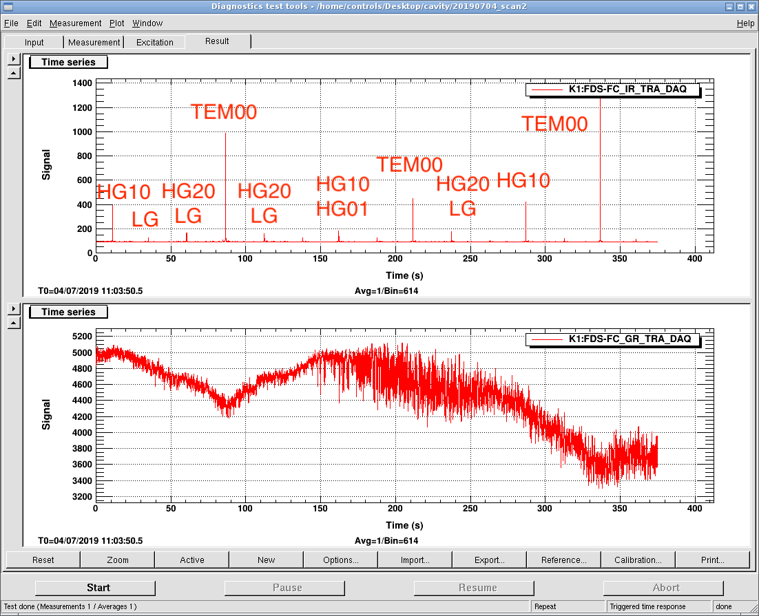
Since lock of green phase is not stable, we scanned green phase with 10Hz and 1.3Vpp. Then we scanned AOM frequency at 2 mHz. After the scan, we locked IR on TEM00 and HG10,01 and measured each power with dataviewer. We repeated alignment of IR and AOM scan twice. Attached pictures show cavity scan. IR transmission when IR is locked on TEM00 and HG10,01 is as follows.
After scan 1
| AOM frequency (MHz) | IR transmission | mode |
| 109.036 | 100 - 2000 | TEM00 |
| 109.43 | 100 - 400 | HG10 |
After scan 2
| AOM frequency (MHz) | IR transmission | mode |
| 109.03646 | 100 - 3800 | TEM00 |
| 109.43133 | 100 - 270 | HG10 |
| 109.432 | 100 - 400 | HG01 |
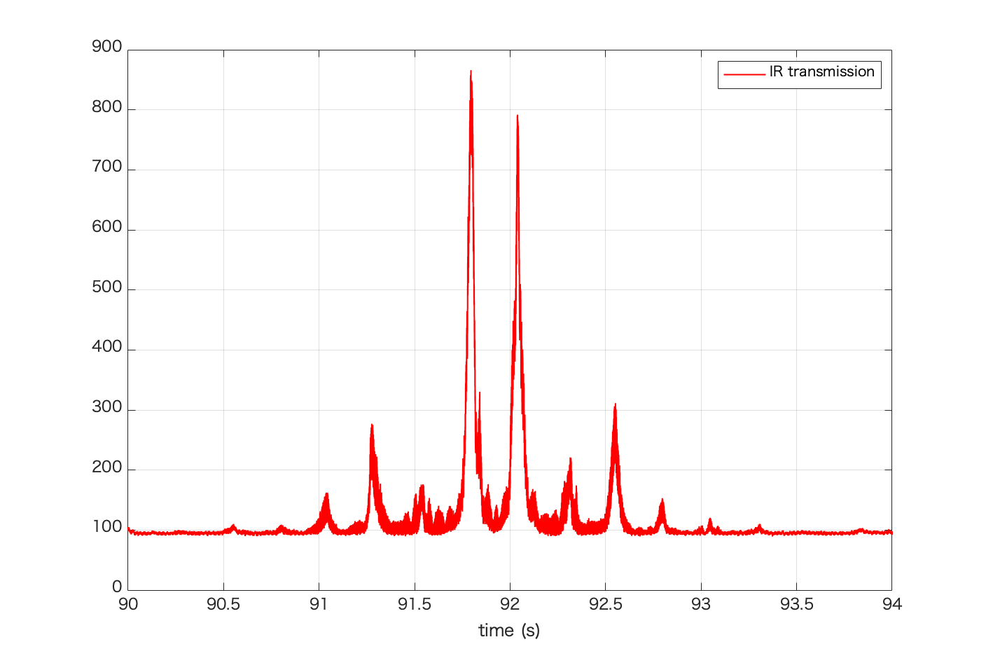
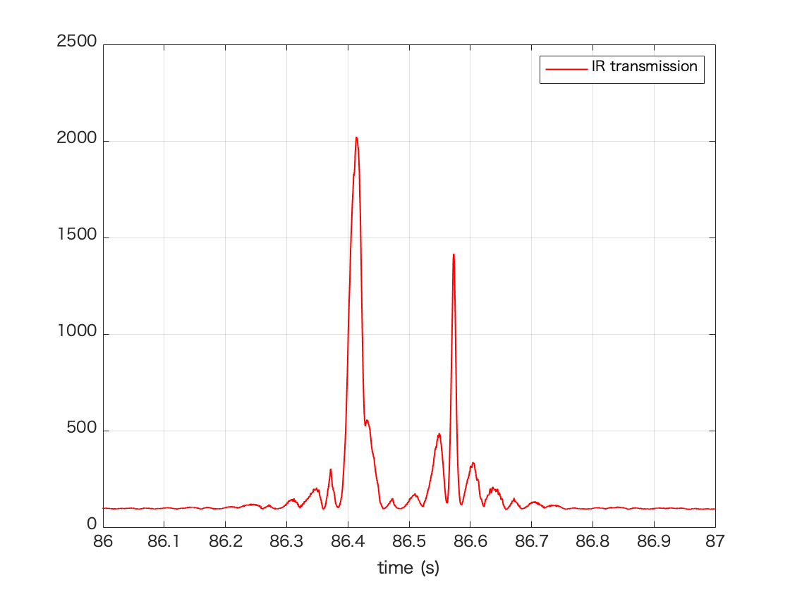
This scan seems strange and is not compliant with measurement when IR is locked due to green phase scan. Pic 3 shows TEM00 in scan 2. Given that linewidth of filter cavity is 100Hz and AOM scan speed is 8kHz/s, frequency of green phase scan should be higher than 80Hz. Actually we tried 1kHz once, but TEM00 peak hight became smaller.
Anyway now TEM00 is 10 times larger than highest HOM. It seems that mode mismatch is small. We'll continue the alignment tomorrow.
This afternoon, Matteo checked my experimental setup, and gave me some advices.
Following his advice, I measured beam profile.
I will upload the results tomorrow...
Today, Aso-san pointed out that the silicon mirrors may have higher finesse than we expected.
Therefore, I checked the spec sheet of mirrors, and the designed reflectance is more than 99.997%, which corresponds to more than 100,000 finesse, though we ordered as 50,000 finesse.
The manufacturer may assume that the loss (probably ~30ppm) reduces the finesse from ~100,000 to 50,000.
However, it may be almost impossible to see transmitted beam with such high finesse and loss...
Today, I re-started the installation of optics for double-pass AOM which is used in HOMs paths.
The beam is aligned roughly.
In addition, I cleaned silicon mirrors using First Contact.
Then I installed them inside the chamber, but still cannot see any flash.
Also I re-designing the cavity in order to make another set of mirrors which have lower finesse and high coating quality.
Firstly after the new measurement of the mechanical transfer funtion of GRMC, the notch filter 2 was modified as below:
The center frequency of the notch filter was tune to 9,47kHz without changing the Q factor (1 as previously).
C60; C63; C61; C62; : 560 pF (unchanged)
R79; R80; R81; R82: 30 kOhm (instead of 24 kOhm previously)
We didn't succeed to lock the GRMC, so I checked completely the filter section of the servo: it appears after measurement of the transfer function of the 1/f filter, that the corner frequency was displaced from 2,2 kHz to 9 kHz.
It appears that the C38 capacitor was damaged. The C38 capacitor was replaced by a 33nF capacitor and the transfers function was restablished.
We always didn't succeed to lock the GRMC. It appears that the error signal in scan mode has an amplitude of -20mv / + 30mV which is weak for the current design of the servo. So the hysteresis of the detection comparator (U23 - LM311DR) was reduced drastically from 10mV to 0.5mV (largely less than the amplitude of the error signal in scan mode).
The R108 resistor was changed to a 10 MOhm resistor (instead of 470 Kohm previously).
After this modification, the GRMC locking was succesfull and robust.
We tuned the gain (position 3 of the gain potentiometer) in order to have a gain margin of 10dB (at phase 0 deg) and a unity gain frequency of 1.6kHz (more than 50 degree of phase margin).
So the GRMC servo is now functional and we can go on the modification of GRMC and MZ servos for synchronized locking.
Error signal is 30 mVpp and conversion factor from V to rad is pi/0.03 = 105 rad/V.
[Aritomi, Eleonora P&C, Yuhang]
This is work on July 2nd.
First we increased green power to 60mW. OPO temperature and p pol PLL are as follows
| green power (mW) | OPO temperature (kOhm) | P pol PLL (MHz) |
| 60 | 7.19 | 150 |
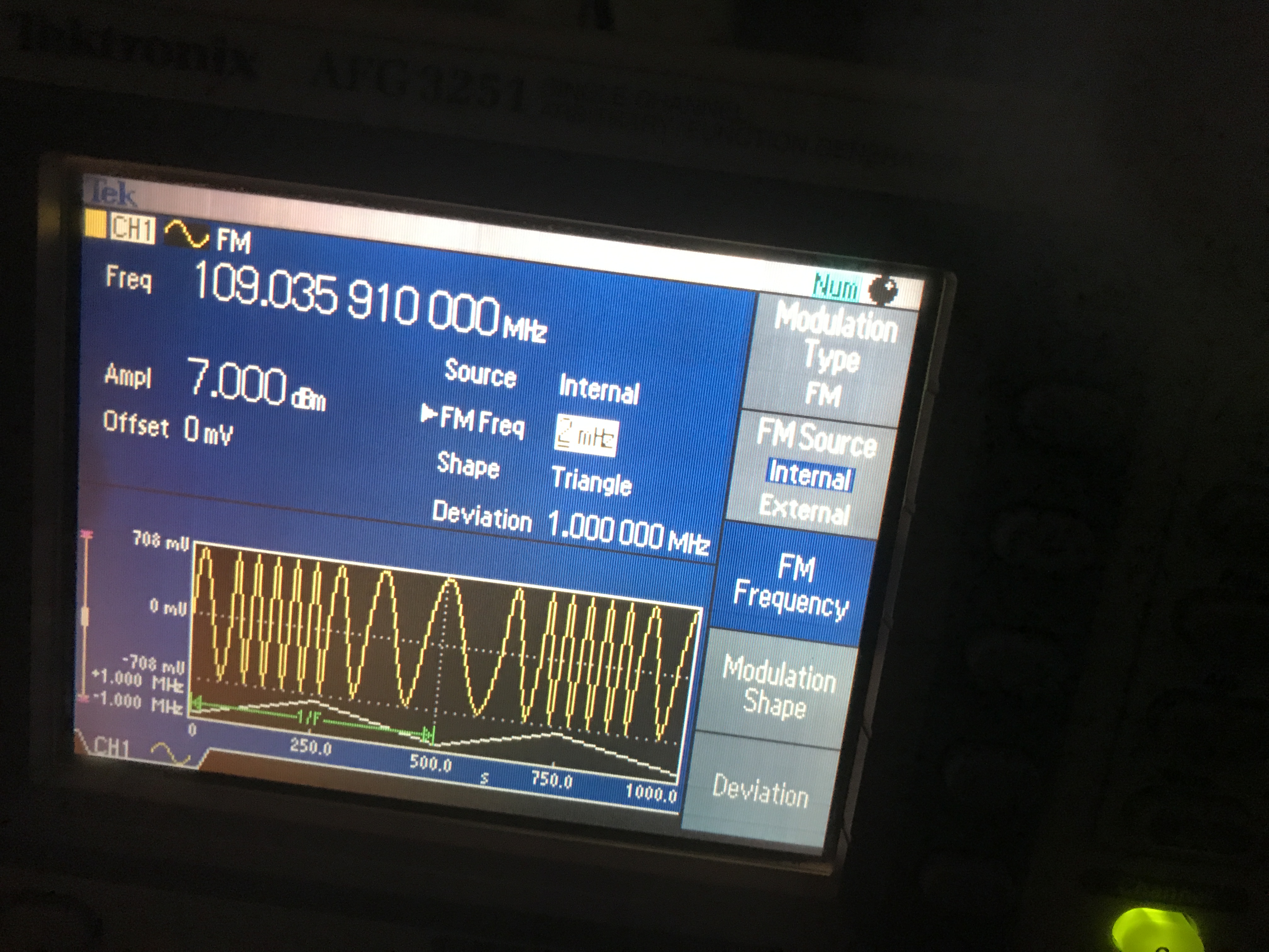
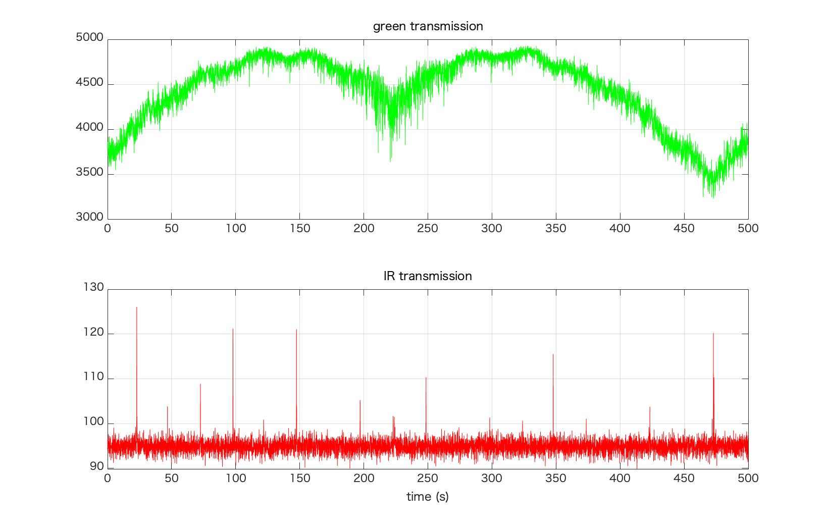
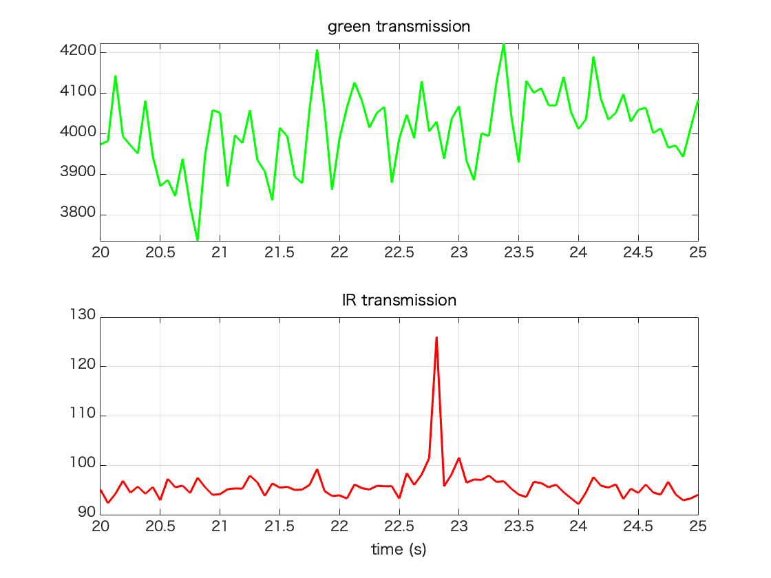
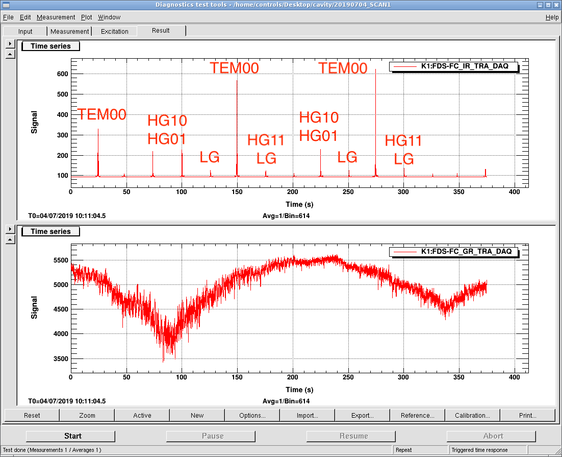
Then we scanned AOM frequency and measured green and IR transmission with diaggui. Note that this data is slow channel and sampled at 16Hz. Setting of AOM is shown in Pic 1. FM is 2 mHz and deviation is 1 MHz (peak to peak: 2MHz). During this measurement, we scanned green phase with 2kHz, 700mVpp. We also took a movie of green and IR camera to characterize higher order modes. Starting time is 19-07-02-07-08-57 UTC. Pic 2 shows transmission of green and IR. Higher order mode is as follows.
| time (s) | mode |
| 22.75 | TEM00 |
| 46.81 | pitch HOM |
| 72.5 | HG10,01 |
| 97.94 | HOM |
| 147.4 | TEM00 |
| 197.1 | HG10,01 |
| 248.6 | HG11,02 |
| 347.8 | HG10,01 |
| 423.2 | TEM00 |
| 472.8 | HG10,01 |
Note that speed of scan is 2 MHz / 250 s = 8 kHz/s and measured FSR is 147.4 - 22.75 = 124.65 s which means FSR is 0.9972 MHz in AOM.
As you can see, green transmission is also scanned by AOM since AOM scan changes alignment of green injected into filter cavity. But this shouldn't be a problem as long as alignment of filter cavity is fixed. When you look at TEM00 closely (Pic 3), sampling rate seems not enough. We'll try with oscilloscope today.