NAOJ GW Elog Logbook 3.2

[Yuhang, Matteo, Eleonora, Miyakawa (remotely)]
Last Friday, just before going home, we noticed that the DGS system was not working anymore and no signal can be read from ADC.
This happend suddenly since we used it up to one hour before and it was perfectly working.
Since me and Matteo were doing some cabling around the rack at that moment, we suspected we had accidentaly disconnected some cable but after a carefull checking it seemed that everything was fine.
On Saturday I contacted Miyakawa-san which accessed remotely the PC and told me it seemed a timing problem. On Saturday afternoon and also this morning we have carefully checked the timing signal.
Following the advice of Miyakawa-san, we change it from square wave of +/-5 V to 0-5V. It didn't solve the problem.
We tried to restart the models and reboot the PC countless times.
I tried to use only one time adapter (and switch it from one to the other) to check if one of the two was broken, but it didn't solve the problem
I tried to double the amplitude of the timing signal, to disconnect and reconnect the cables between AA, time adapter and I/O chassis. It didn't change the situation.
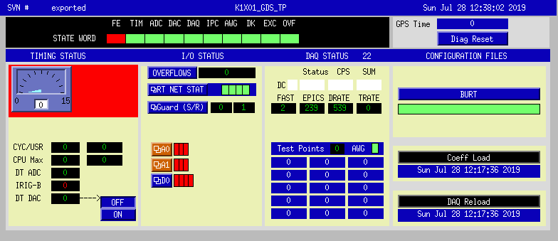
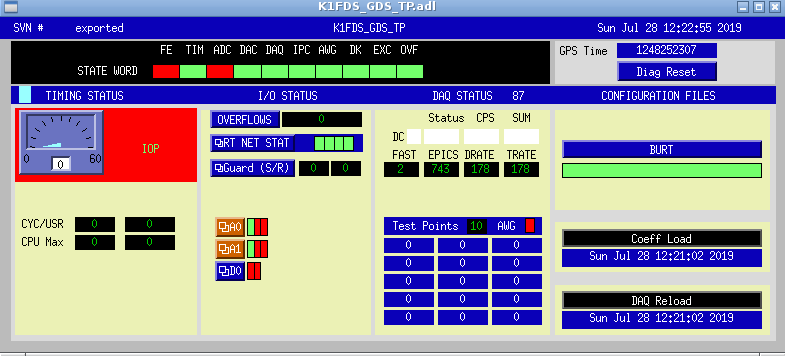
Pic.1 and 2 show the errors that appear in the DGS_TP screen for K1x01 (master model) and K1FDS (slave model), respectively.
We really need the help of an expert.
On top of that it seems the screen connected to the standalone doesn't work properly. Sometimes it gets black and we need to switch it on and off to recover it (but it usually last few seconds and then gets black again!)
[Matteo, Eleonora]
On Friday 19/08 we recived from Kamioka one AA module and two BNCtoDsub converters.
Last week we have installed the AA into the DGS rack and did some cabling from this rack to the cleenrrom as we blan to install the BNCtoDsub converters into the clean room rack.
We took a power supply from ATC and use it to power a KAGRA DC power strip (also taken from ATC). We use the strip to power all the two AA, the AI and the DAC dSub->BNC converter (not that ADC BNC-> dSub converters don't need power.)
We reorganize the cables behind the DGS rack to make them more tidy.
We also removed one ADC PCiexpress card from the new DGS computer (the one we couldn't make work) and installed it into the standalone PC we are currently using.
The standalone can host up to 4 card and we have currently installed two ADC an one DAC. The slots are piled up in vertical. From the bottom we have
1) ADC 1 (used for local controls)
2) ADC 2 ( not used, it will be used for AA signal)
3) DAC
4) empty
In the future we can decide to put another DAC or another ADC in the empty slot. According to Miyakawa-san all the possible combinations of 4 PCie among ADC and DAC are fine with the excepion of 4 DAC.
We took an additional timing adaptor from ATC which we used to provide the timing signal to the new ADC card.
We haven't tested the new ADC but the system seemed to work fine after these modifications. We didn't experienced any trouble until the failure of last friday (26/07).
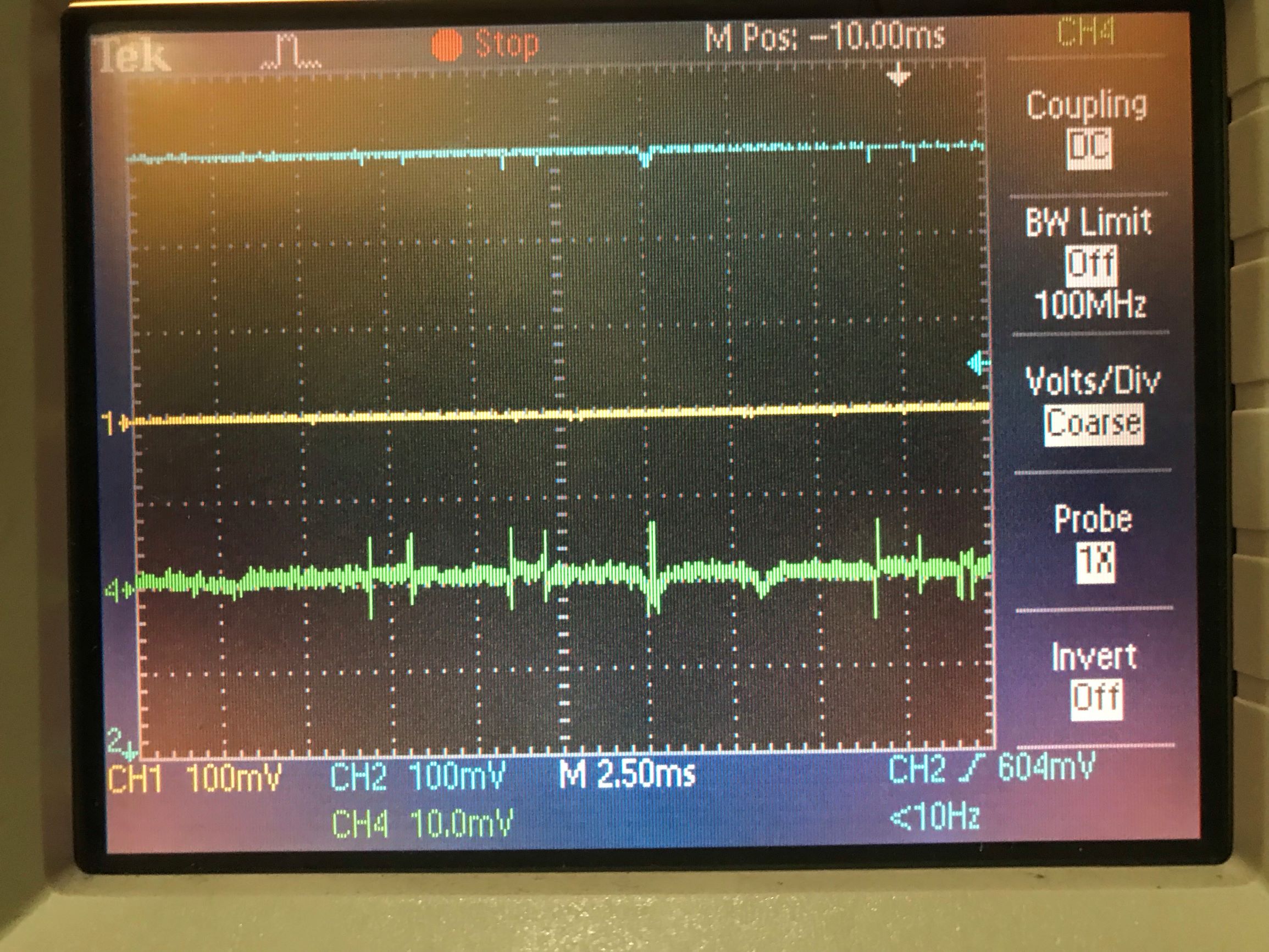
I checked PDH error signal (green line) with low-pass filter.
Though the time resolution is higher than before, still the error signal is spike-ish structure.
This may be due to too high finesse of silicon cavity.
At this moment, I did not use frequency scan by laser PZT, but temperature fluctuation of laser induced frequency fluctuation.
Thus I could see error signal without scanning laser frequency.
It needs temp. control loop for stable lock.
Anyway, I will consider cotrol loops for TEM00 lock.
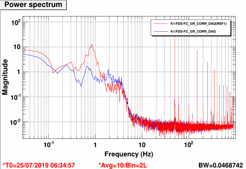
I tried to feedback a part of the PZT correction (sent to the main laser to lock it to the FC) to the end mirror. The goal is to reduce the cavity motion at the logitudial resonance frequency (around 1Hz), acting on the mirror in order to reduce the correction sent to the laser. In fact in this region, the correction increases the frequency noise of the main laser, inducing higher PLL noise.
The PZT correction is taken from the channel "pzt mon" of the rampeauto (which is 100 times smaller that the real correction), it is sent to the ADC of the DGS where it is digially filtered and then the correction is summed to the one already sent to the end mirror coils (from anguar damping).
We observed that the signal seen by DGS has a very strong 50 Hz, which is not present when locking at it with the oscilloscope.
In order to select the part of the spectrum aroun the 1Hz, I used a filter like this:
| Freq (Hz) | Q | |
| zero | 0 | simple |
| pole | 1 | simple |
| pole | 20 | simple |
| pole | 20 | simple |
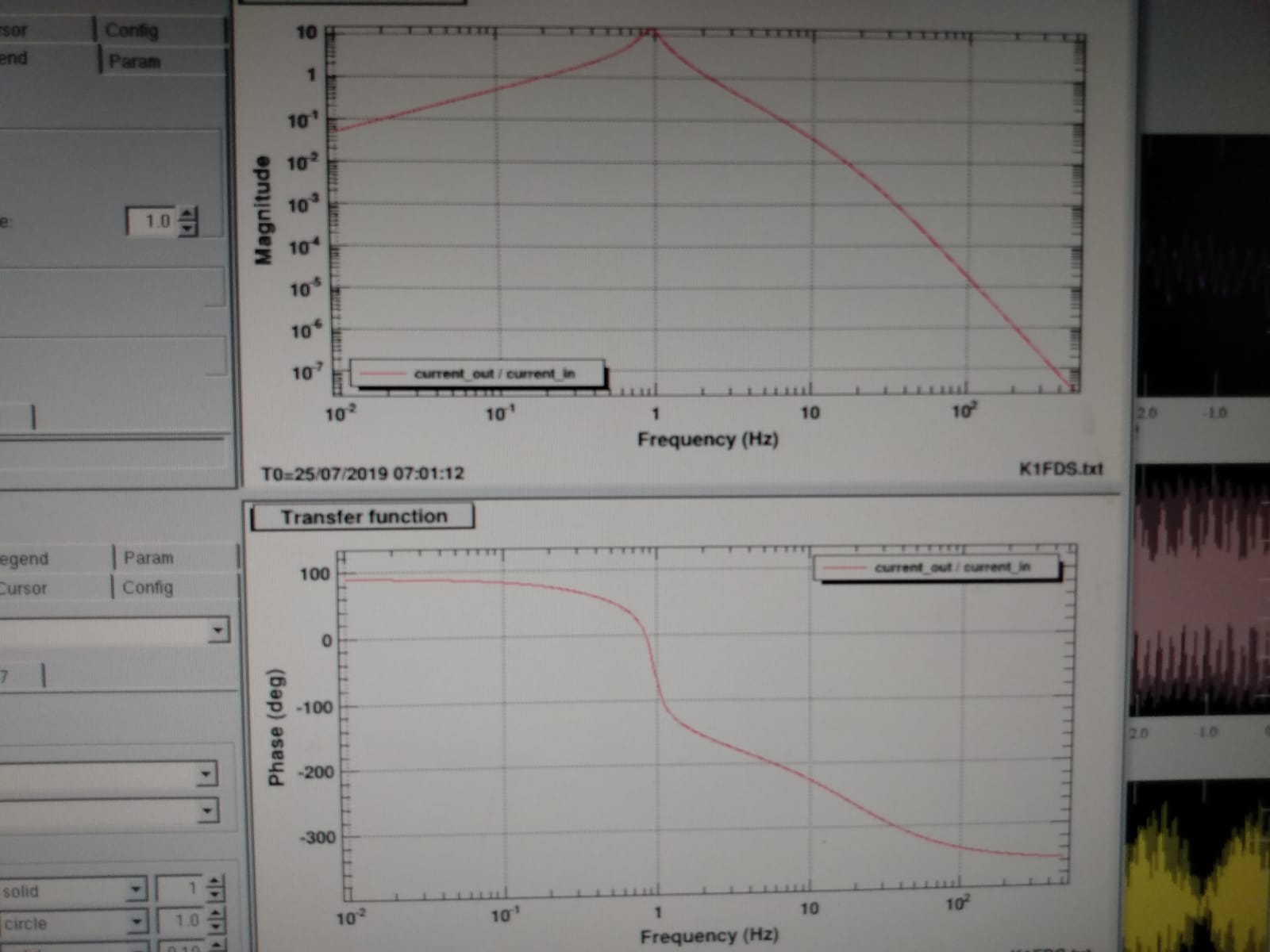
The simulated openloop TF is shown in pic1. Where as a mechanical TF I used the one measured in entry #1506
Pic.2 show the spectrum of the PZT correction with (bue curve) and without (red curve) test mass feedback engaged. It can be seen that the correction to PZT is reduced by a factor ~10 in the 1Hz region when the feedback is engaged (blu curve).
To be done:
- Amplify the signal before the ADC with a stanford to better exploit the ADC dynamics.
- Check the RMS improvement and optimize the correction filter (an overshoot is now visible at 2-3 Hz).
- Add a notch filter to avoid feeding back the 50 Hz and to be able to check the signal improvemt in time (currently it is fully dominated by the 50 Hz).
- Check wheather the PLL noise is reduce when the loop is engaged.
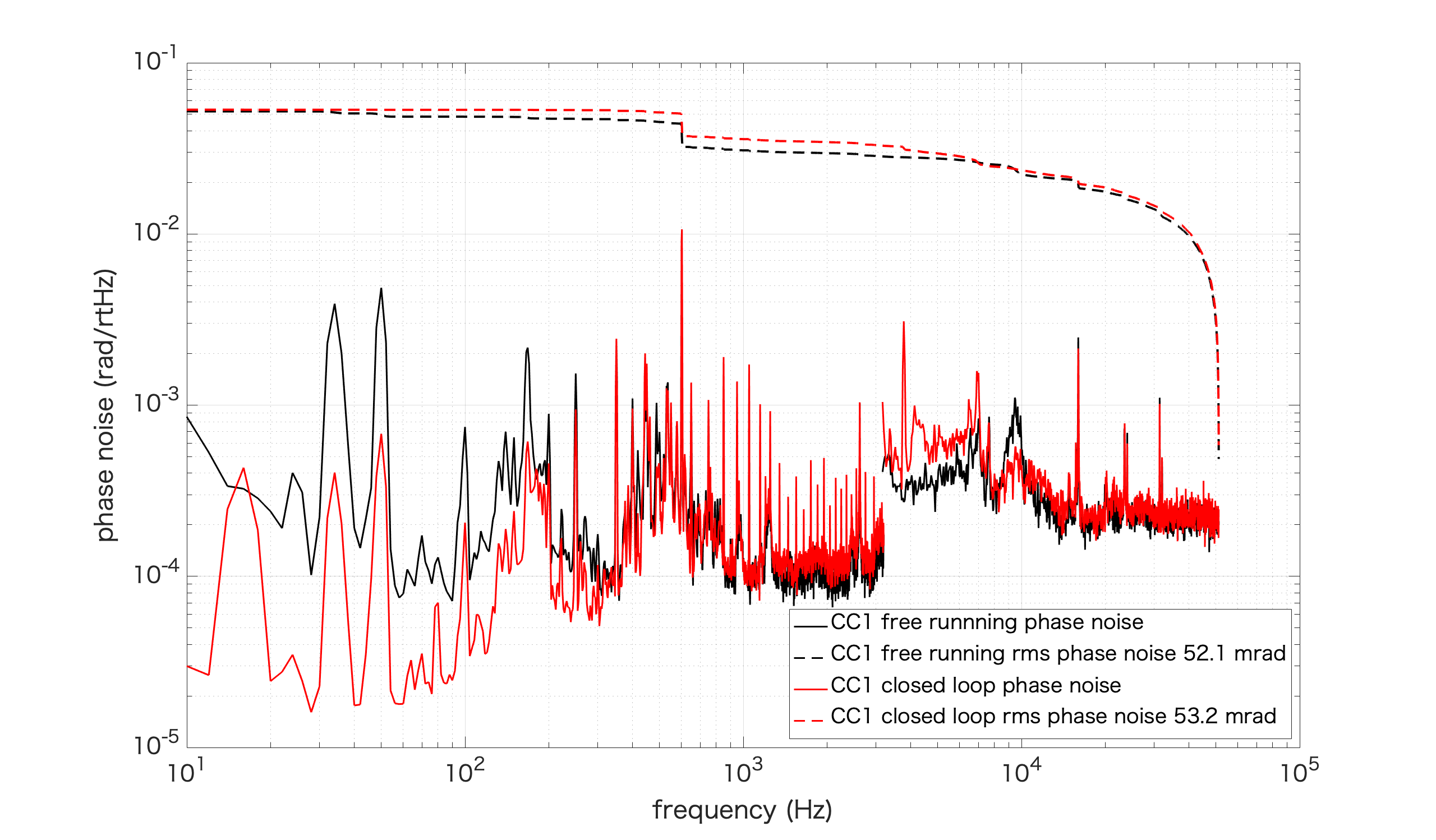
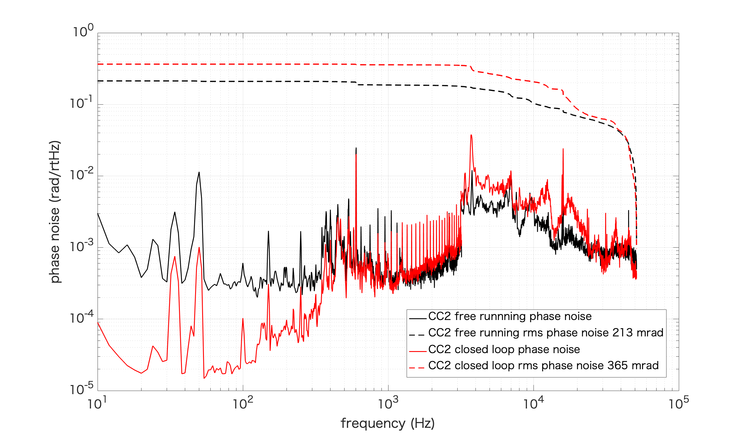
[Aritomi, Yuhang]
First we moved position of green phase shifter closer to GRMC since effect of misalignment of green phase shifter was large due to rubber and also there was no space to put additional clamp to fix green phase shifter.
Then we measured free running and closed loop phase noise of CC1,2 (attached pictures). We measured EPS2 of servo as error signal. Note that EPS2 of servo is larger than real error signal by a factor of 15.
As you can see, phase noise above 400Hz is very large and rms phase noise is mostly accumulated at high frequency where phase noise is not suppressed by CC loop. When we close the CC loop, phase noise at high frequency becomes larger and rms phase noise becomes even larger. This measurement is consistent with recent noisy squeezing measurement.
So far, I installed an AOM and some mirrors which consist double pass AOM configuration.
I install a lens in order to avoid clipping at AOM.
Then I adjusted the alignment, and double-passed light can be picked off by PBS now.
Although I have not driven the AOM, the first rough alignment has been done.
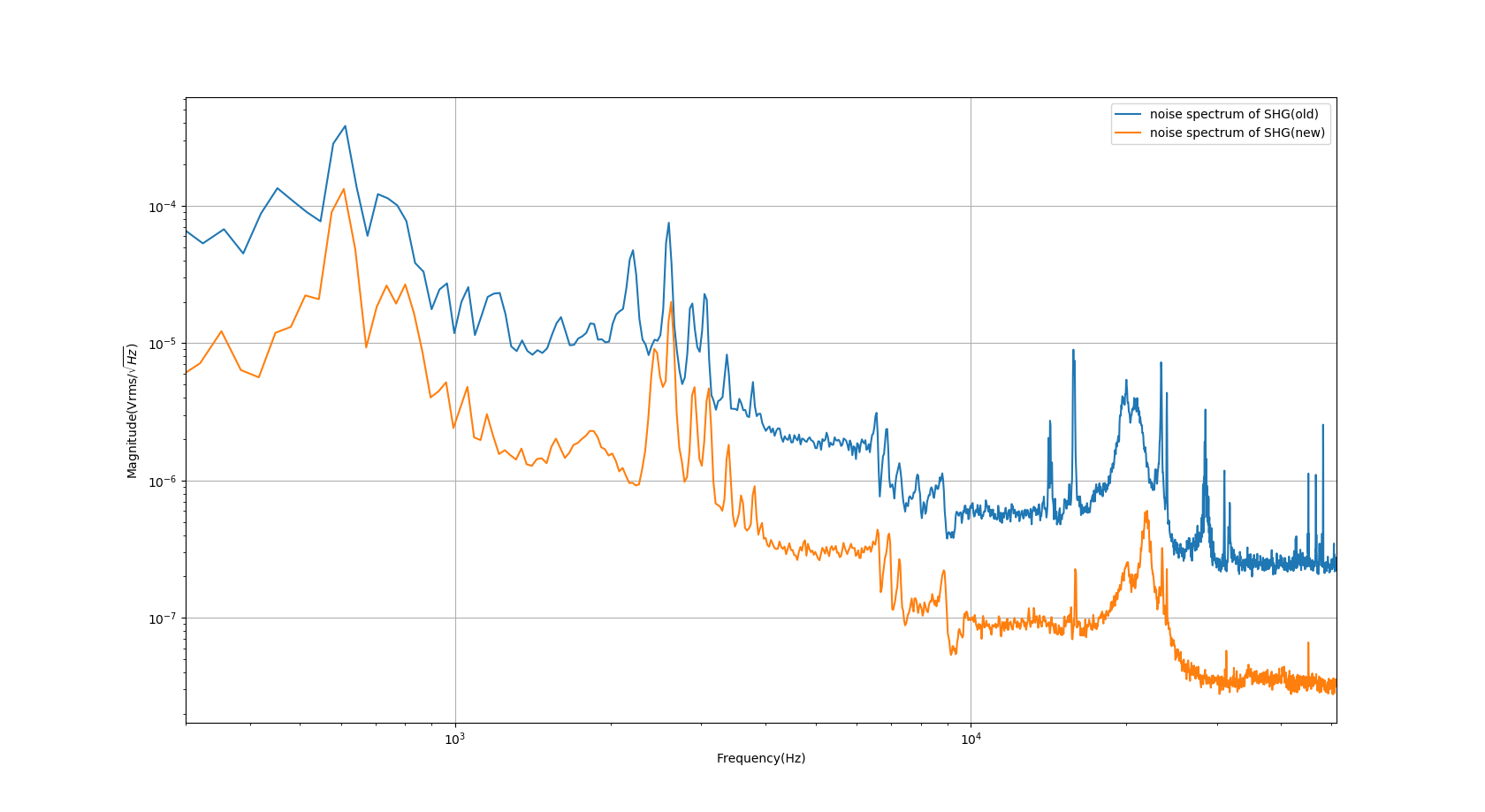
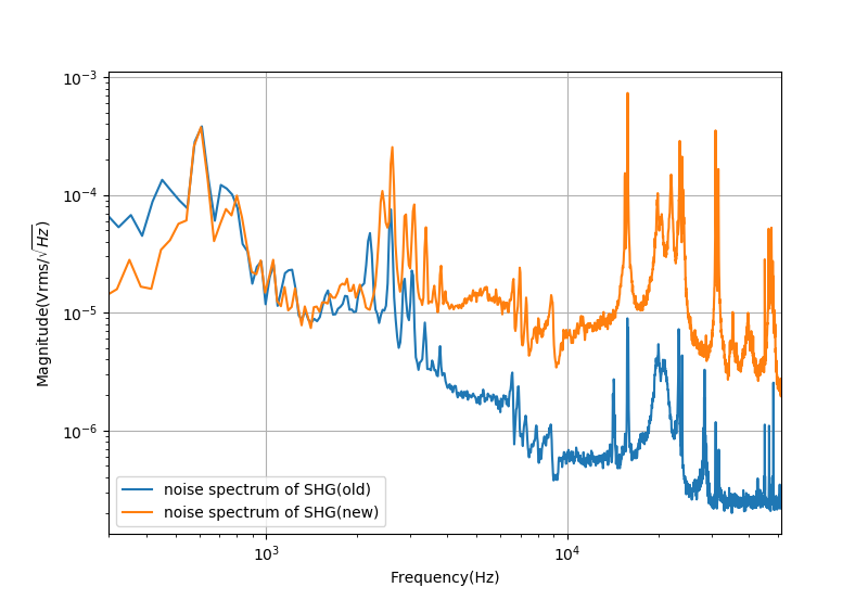
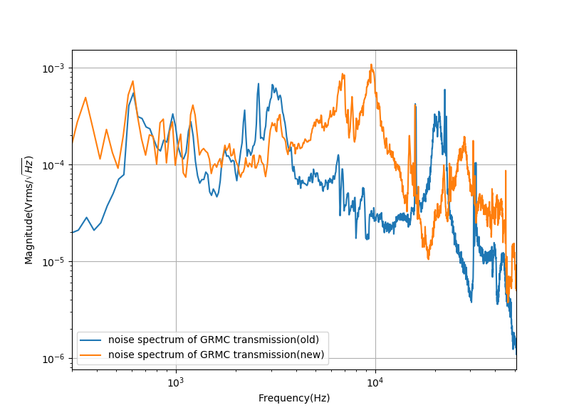
Here I attach the measurement of SHG and GRMC transmission noise spectrum.
The difference is I measured the noise spectrum of SHG transmission at a wrong place. (Actually, I was measuring the locking noise of SHG in the entry 1501)
However, we really have a worse GRMC transmission noise. Especially, there are peaks from the 4-10kHz region. They are responsible for the region where we have more noise in the squeezing measurement.
I will try to understand why there is a factor between the old and new measurement.

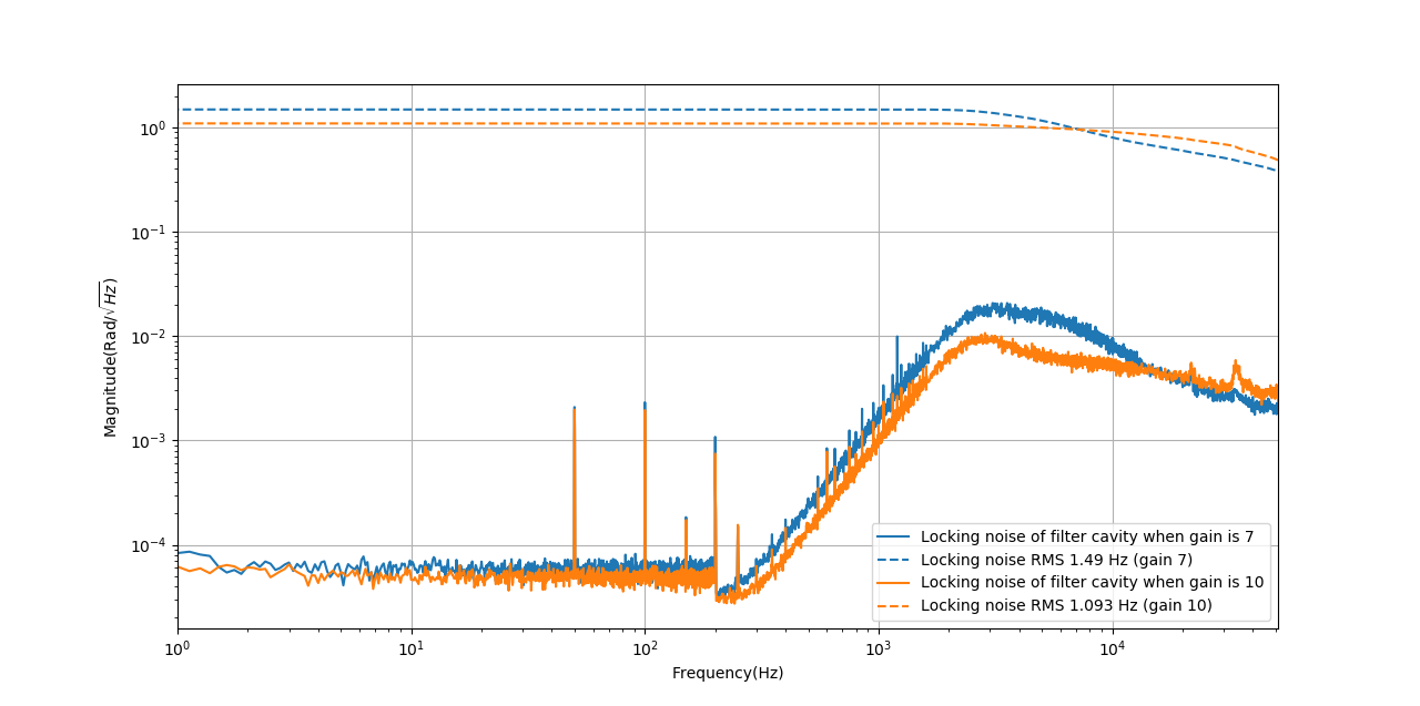
The measurement done last week shows RMS locking noise is much lower than we expect(entry 1486). It was almost 50 times lower than the measurement done last year(entry 642). So we decide to double-check by using time series.
I did the measurement of RMS locking noise when the gain is 7 and 10. The result is shown in the attached figure 1. However, I just realized the gain of 10 sometimes brought some resonance(I didn't find this resonance last week). Now the gain of filter cavity lock should be 7.
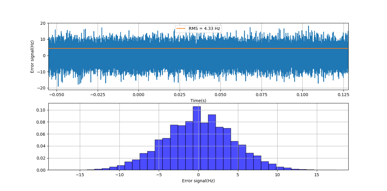
Then I measured the time series of the error signal. And the calibration result is attached in figure 2.
The measurement of time series shows RMS as 4.33Hz while FFT shows 1.5Hz. Basically, they are very similar.
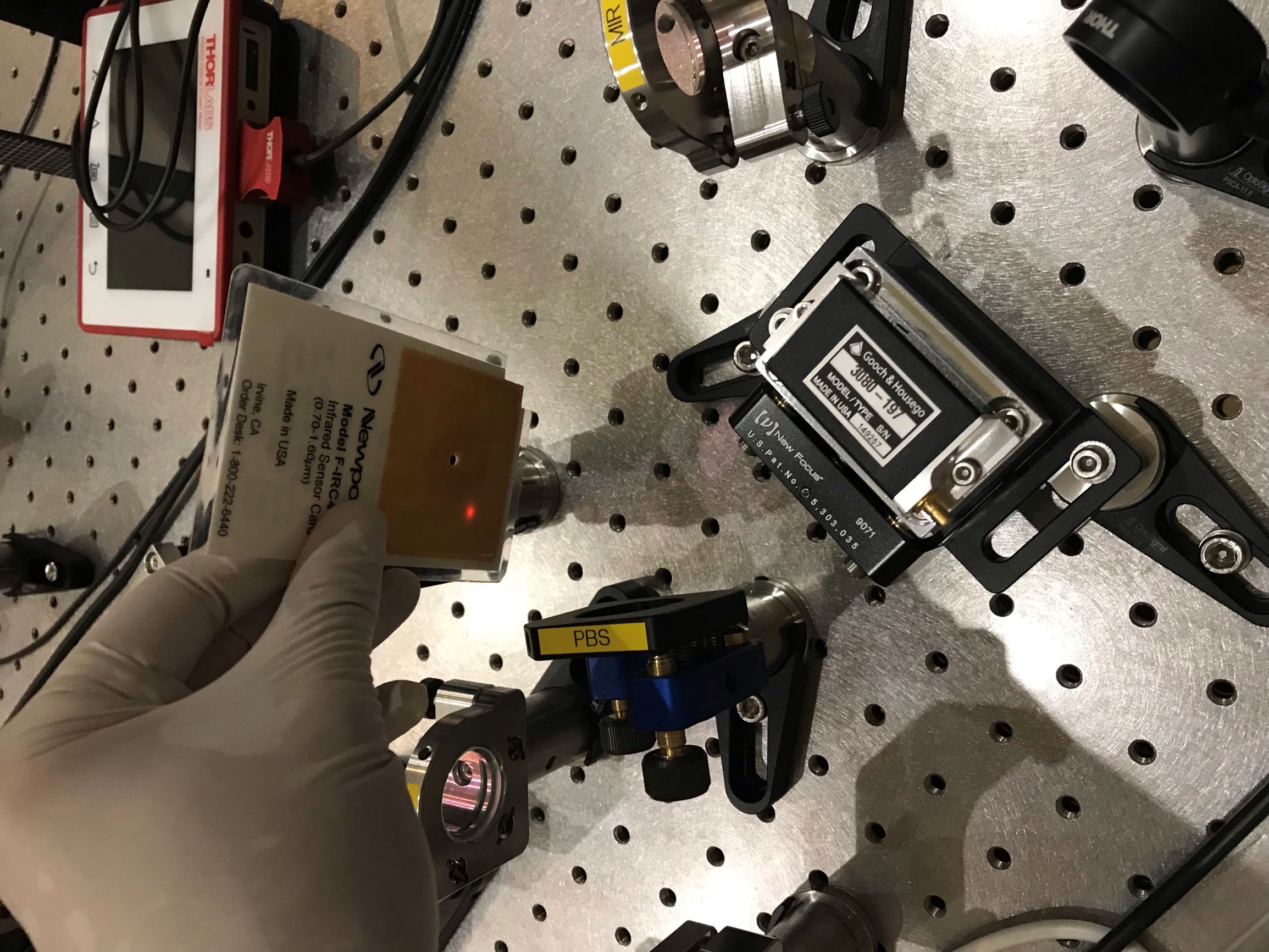
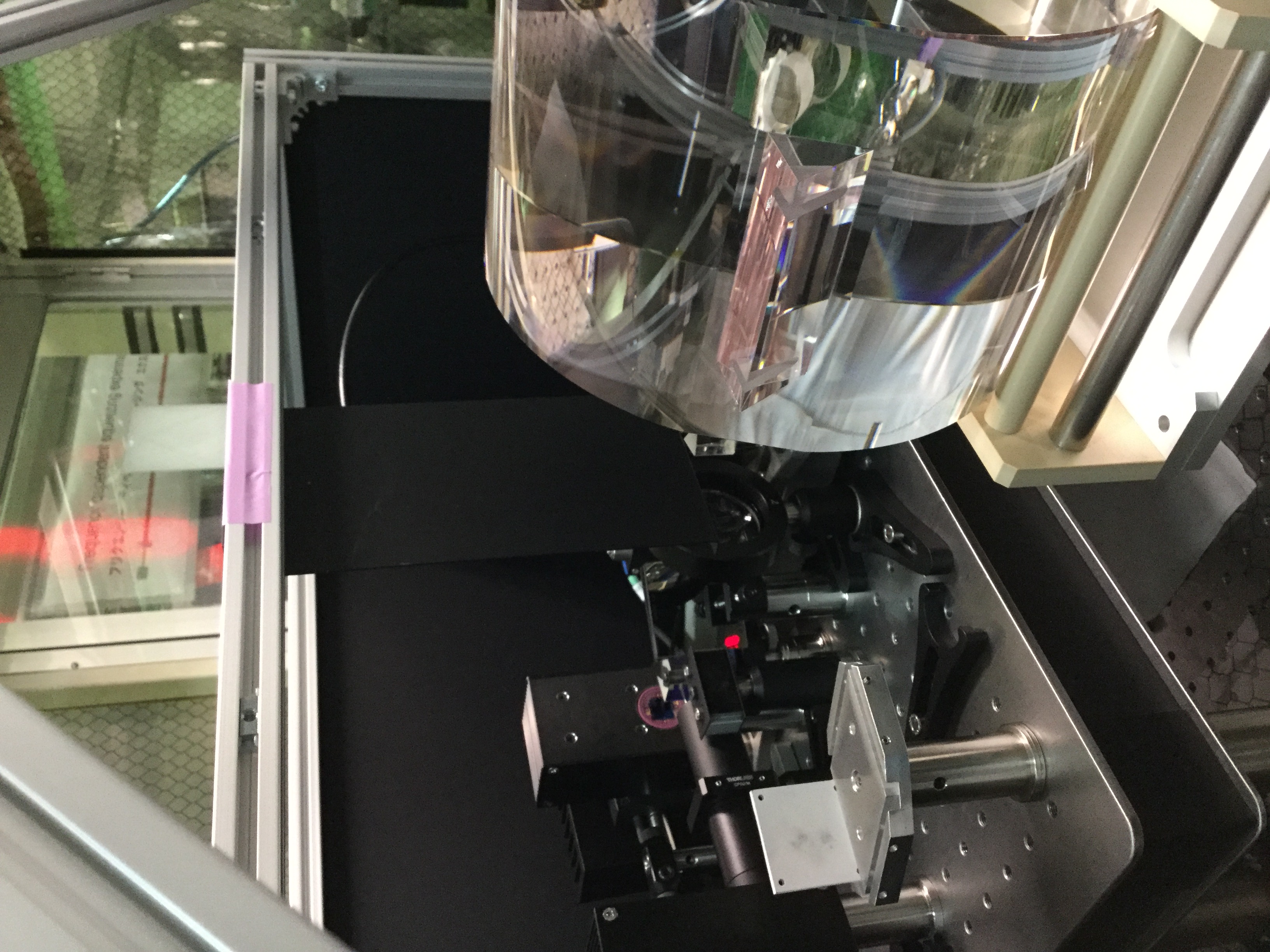
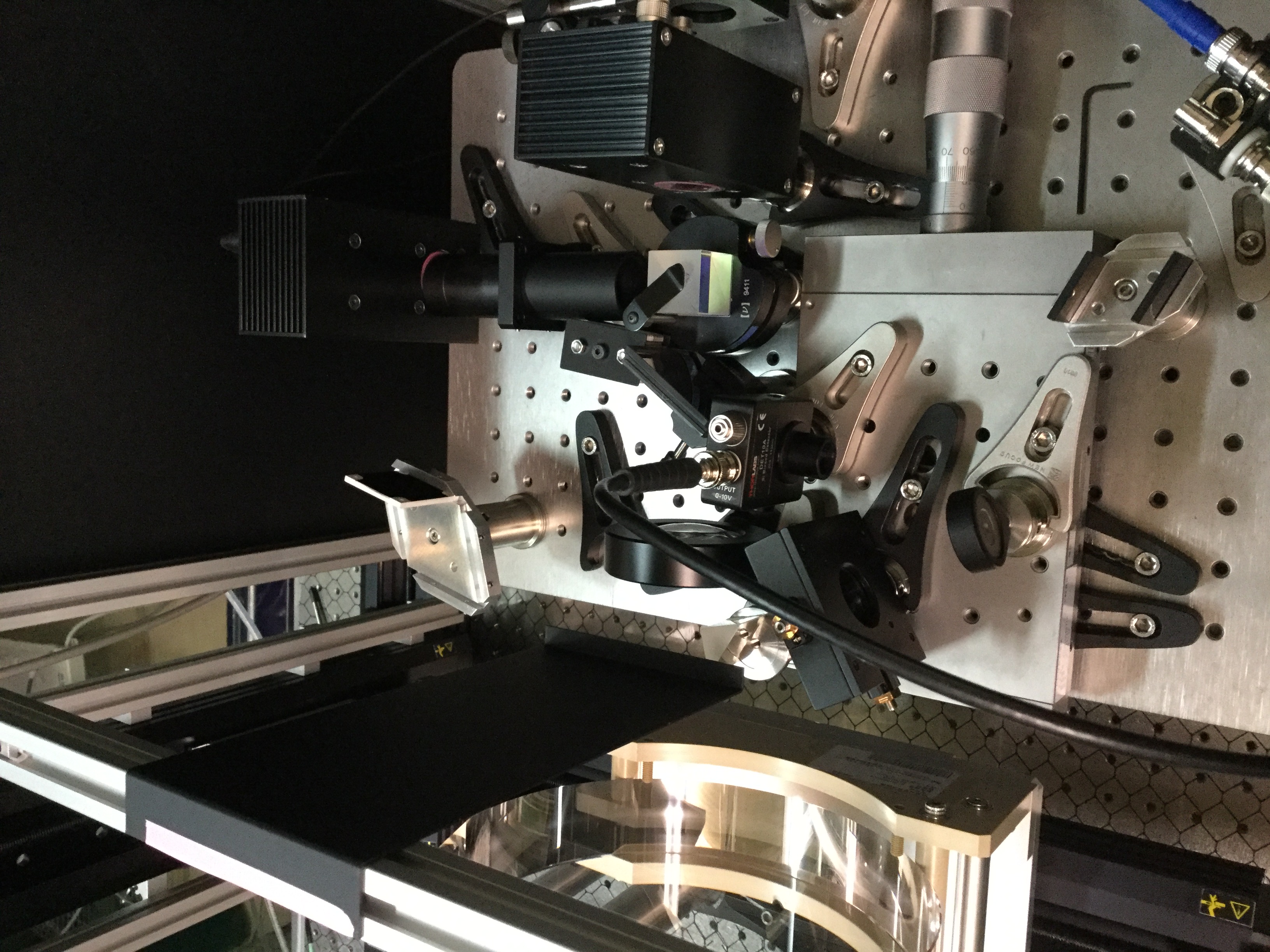
Matteo, Eleonora, Simon
We have changed the setup of the absorption bench so to be able to measure S and P polarization of the transmitted beam.
The basic point in the new setup is that we are using two photo-sensors (PSDs, to be more specific) and a PBS together with a lens to focus and split the beam.
Since the measurements are very sensible to the setup, we needed to take several aspects into account:
-
Incoming beam needs a good initial alignment in terms of polarization
- another PBS and a HWP were installed
-
The PSDs are too sensitive for the pure transmitted beam
- A stack of ND filters were installed between lens and PBS in the outcoming beam-path
-
The setup is extremly sensitive to stray-light
- A beam-tube is covering the PSD in the lateral beam-path from the PBS (S - polarization)
- A beam-dump (Vantablack) is catching the reflected beams from the ND-filters
- A razor-blade beam-dump is covering the space btw. beam-tube and ND-filters (catching scattered light)
- A couple of obligued ND-filters is placed at the blind-side of the PBS
- A black light-cover is placed on top of the lens to catch some ghost-beam reflections coming from the top of the sample
Especially the stray-light suppression is challenging as there are a lot of possibilities where scattered light can enter the sensors and it may be that we still find new sources.
For example, one main source of stray-light was a ghost beam created by a probe-prism which is reflected by a lens for the incoming pump-beam, and this reflection is entering the test-mass and internally reflected on the upper boundary and eventually entered the P-pol sensor from above (shielded now - see pictures)
Electronics
We are using basically the same system as already given by the absorption-bench setup.
However, we had to do some modifications:
- As we have only one channel to demodulate an AC signal on the lock-in, we have installed another lock-in to demodulate the signal from the second PSD (using the same reference signal)
- The power for the measurements is reduced to be in the mW region (2A input current)
- Of course more cables and power-sources needed for the sensors
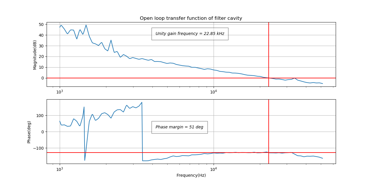
I upload here the open-loop transfer function of the filter cavity. The situation now we are operating with.
(gain of 7, attenuation of 7)
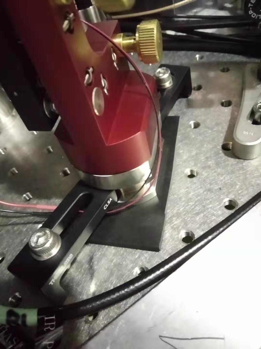
Aritomi and Yuhang
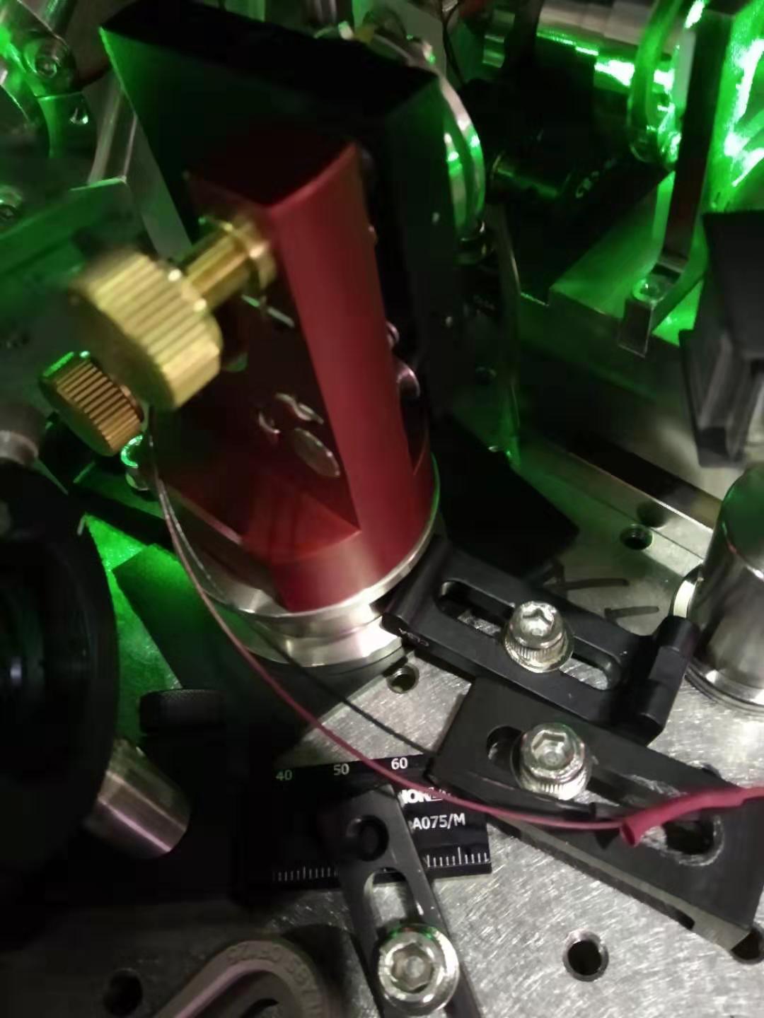
After seeing the effect of rubber in entry 1508, we tried to put it at another position. Considering what we reported in entry 1471, we found the resonance of 500Hz/600Hz is due to different base plate we put for phase shifter. So it seems to be an overall resonance of the mirror mount.(flag pole mode) So we decided to put a piece of rubber under the whole mirror mount. We thought it will damp the resonance of 500Hz/600Hz. The rubber and the position we put for CC1 and CC2 is shown in the attached figure 1 and 2.
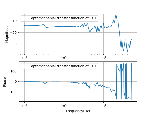
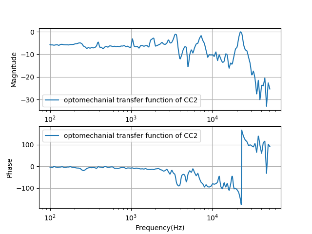
After put them we increase gain little by little, we couldn't find the resonance of 500Hz/600Hz. It makes a big difference. The measurement of the optomechanical transfer function is attached.
[Aritomi, Yuhang]
First we put rubber under phase shifter to damp 500Hz resonance. 500Hz resonance almost disappeared with rubber and finally we could lock CC1 with 4kHz bandwidth and CC2 with 1.5kHz bandwidth. CC2 is still a bit unstable and maybe integrator is necessary for CC2.
Then we measured squeezing spectrum, but the spectrum is similar with before...
Tomorrow we'll measure free running and closed loop phase noise of CC1,2 to estimate phase noise.
Yuhang and Aritomi
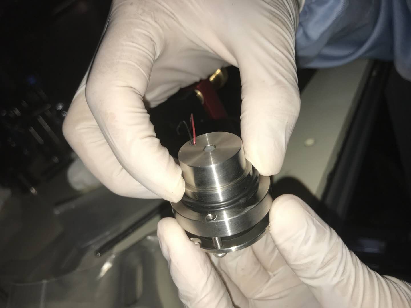
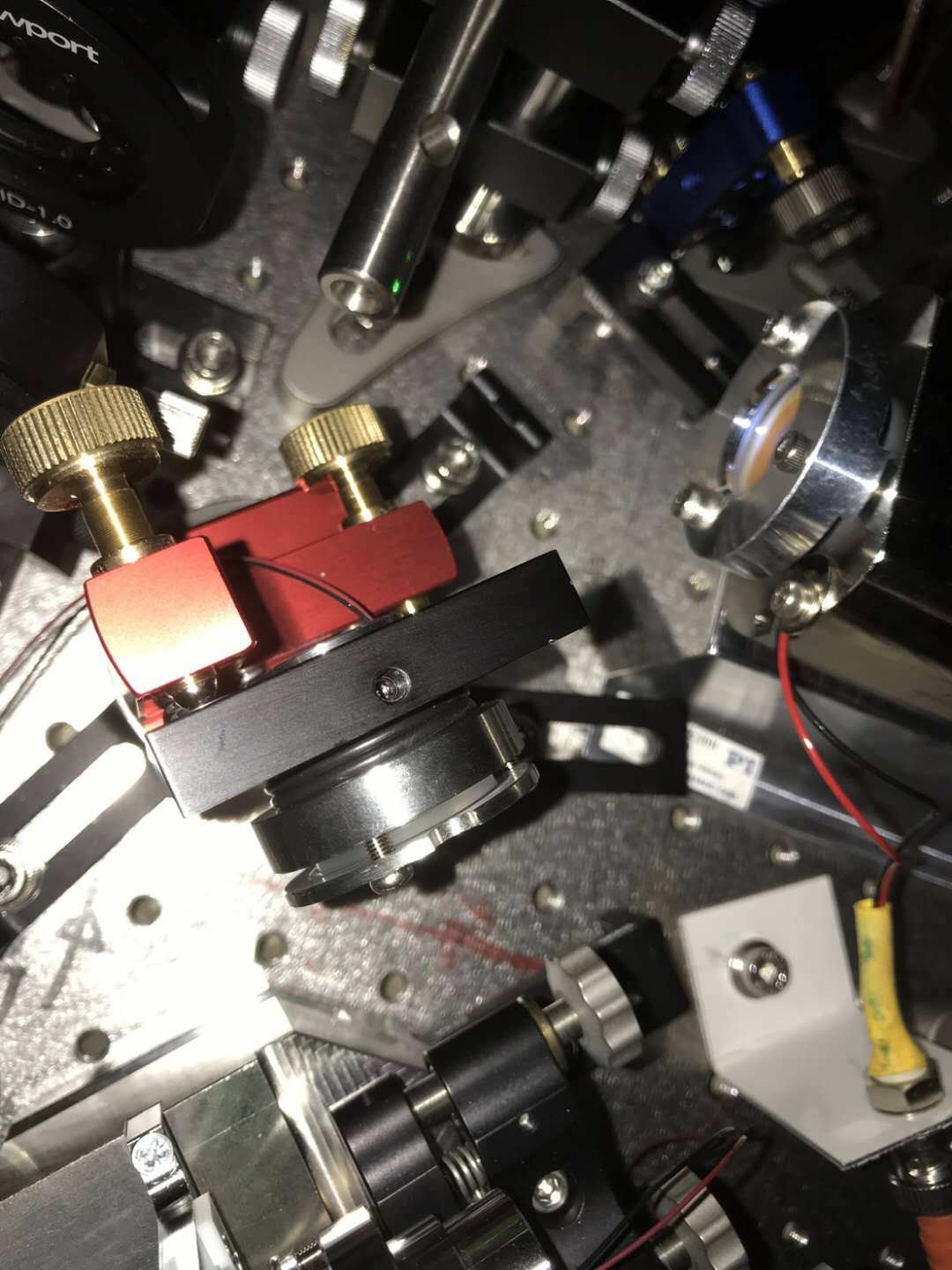
We tried to put a rubber at the place where we think it can be related to resonance. First, we tried to put it between mirror/PZT holder and mirror mount. See attached figure 1 and 2.
In the measurement shown in entry 1503, CC1 has already been installed with this rubber while not for CC2. In this entry, I put a comparison of OLTF for CC2 with and without the rubber.
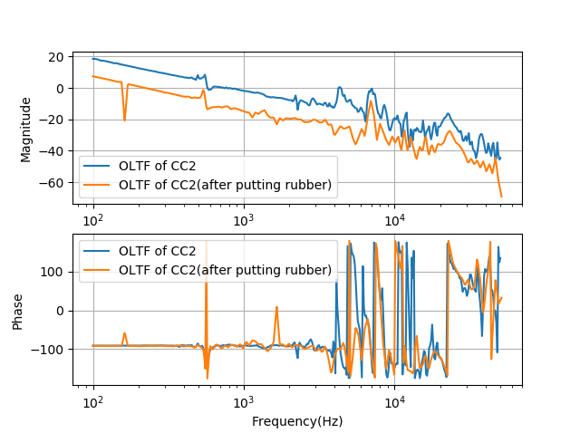
In the attached figure 3, it is shown the measurement with and without the rubber. We can see 4kHz resonance is damped.
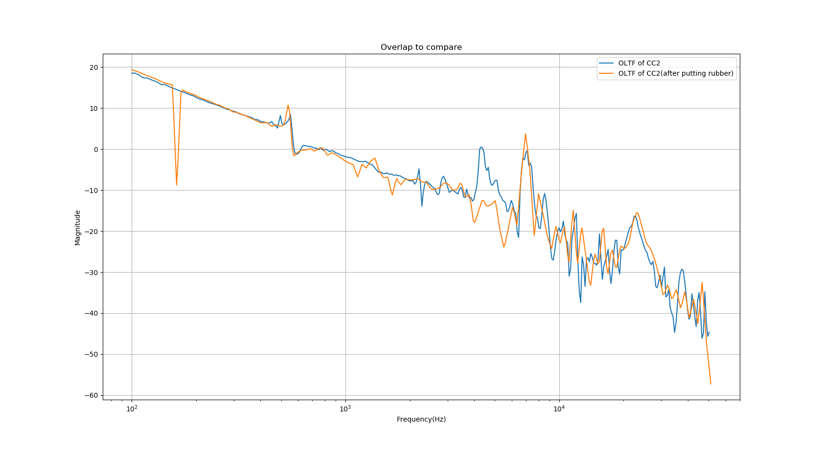
In the attached figure 4, I add 12dB to measurement with rubber. The reason is we were locking with different unity gain frequency. In this case, we could compare better. From this comparison, we could see that the reduction of resonance at 4kHz gives energy to the peak at 600Hz and 7kHz and makes them higher.
Considering the position we put rubber, we think 4kHz corresponds to resonance along the direction of mirror/PZT holder axis.
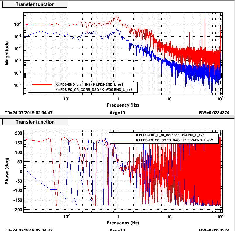
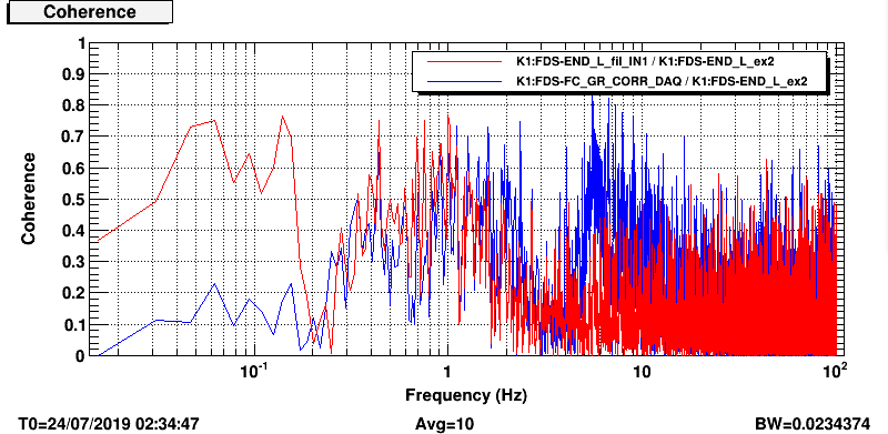
I injected noise on lenght d.o.f of the end mirror when FC is locked and measured its TF to legth oplev and correction signal to the laser piezo.
The TFs look similar (pic 1) even if they are not very clear and the coherence is quite low. (pic 2).
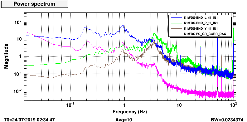
The noise amplitude was 10000 count (~3V) and the driving matrix was such that only vertical coils where used. (It should couple only with pitch)
Pic 3 shows the spectra of the other d.o.fs. The damping loops were closed at that time, but pitch shows a motion larger that usual.
1. For main laser power line. The board should have a hole 11.1cm away from border and 4cm high.
2. For green injection, the beam is at the edge of the board. Height of 7.55cm
3. For IR injection, the beam is 37.2 holes(each hole 2.5cm) away from main laser side.
4. length of homodyne power cable should be 5m
(Please look at attached figure to make it clear about where should be the holes)
[Aritomi, Yuhang]
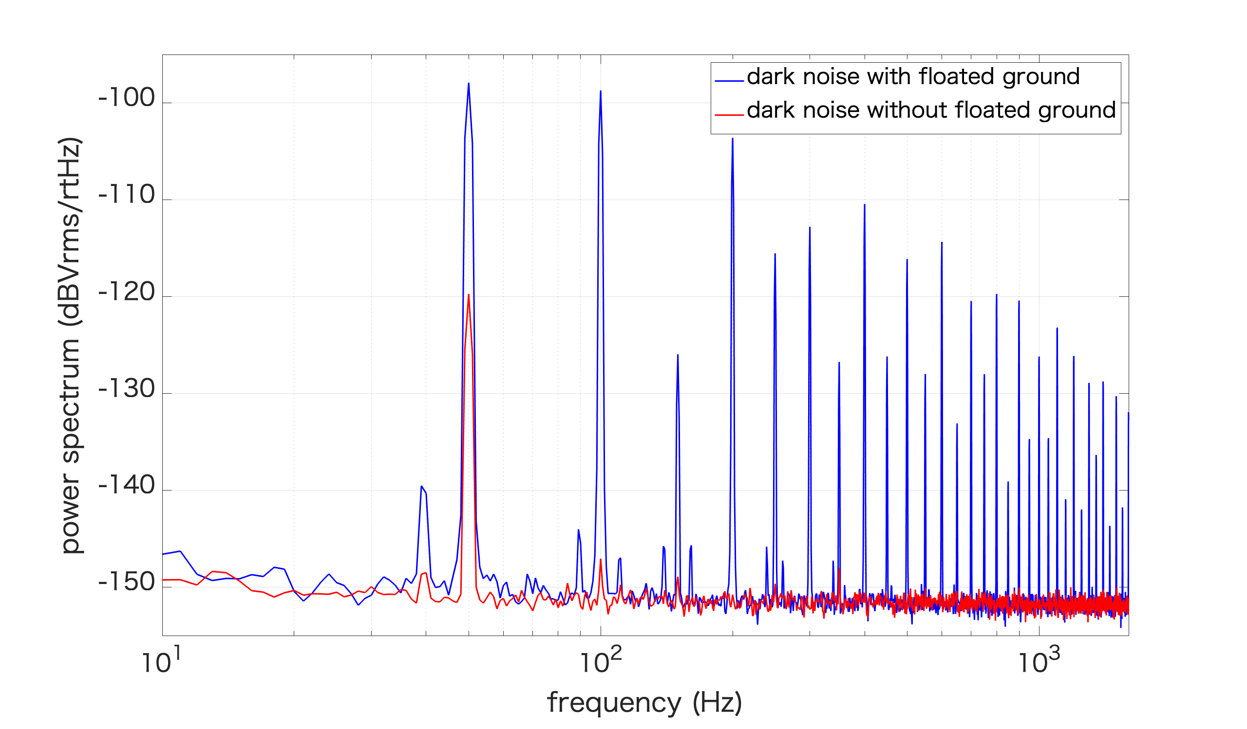
First we measured dark noise of homodyne since we had large 50Hz noise in shot noise spectrum. The dark noise already had large 50Hz noise and we found that when we removed ground floating of spectrum analyzer we are using, these peaks disappeared (Pic 1).
For CC, we checked noise in SHG, GRMC (entry 1514). Then we tried to lock CC1 and 2. For CC1, at the beginning of today we could lock CC1 in stable region between 500Hz and 7kHz resonance, but at the end of today, we couldn't find stable region somehow. For CC2, we couldn't lock it stably so we put rubber to CC2 mirror holder and 4kHz peak is damped (entry 1508), but we still cannot lock it because of 7kHz resonance. 4kHz resonance should be resonance of mirror holder, but we don't know where 7kHz resonance comes from.
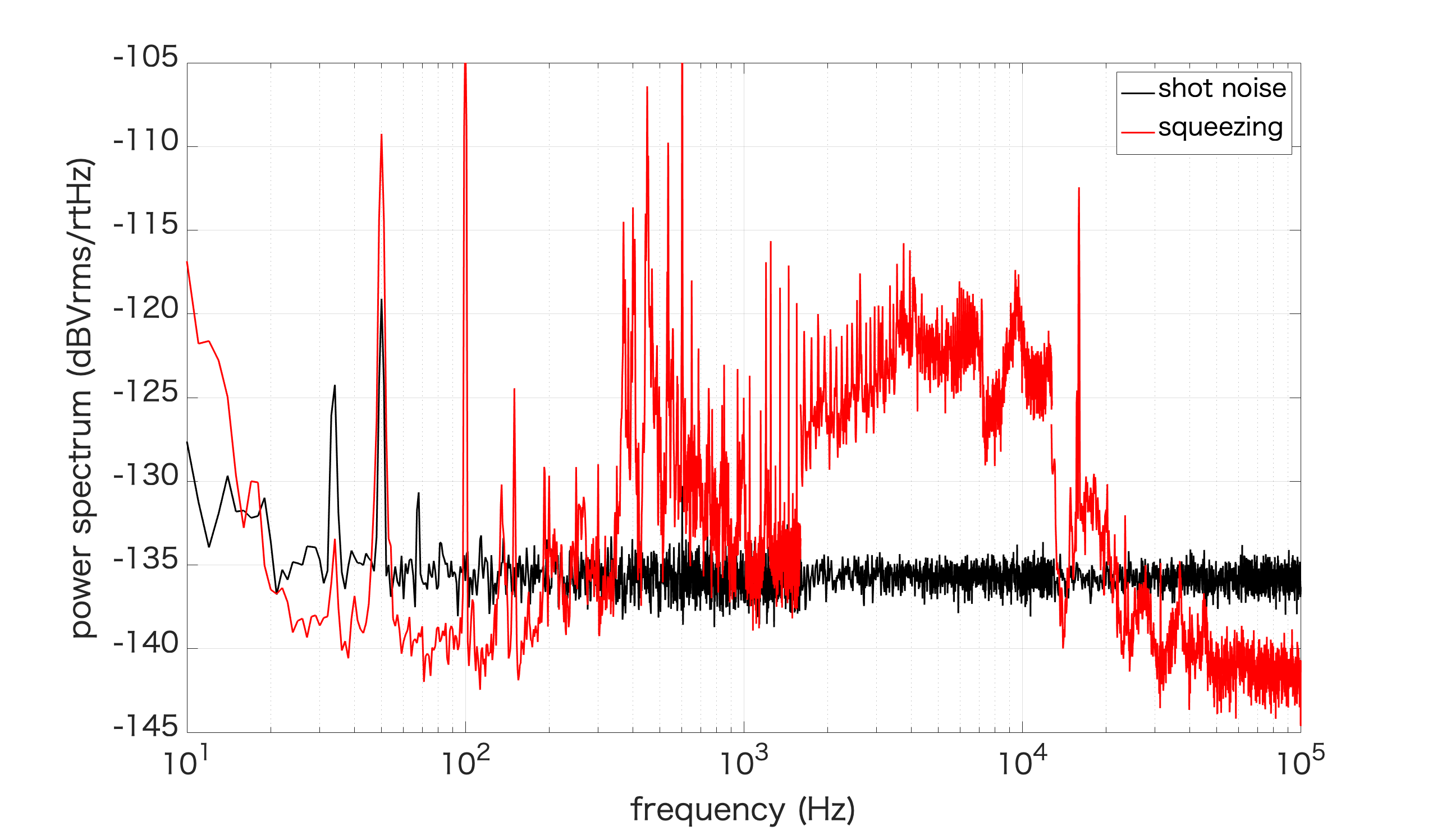
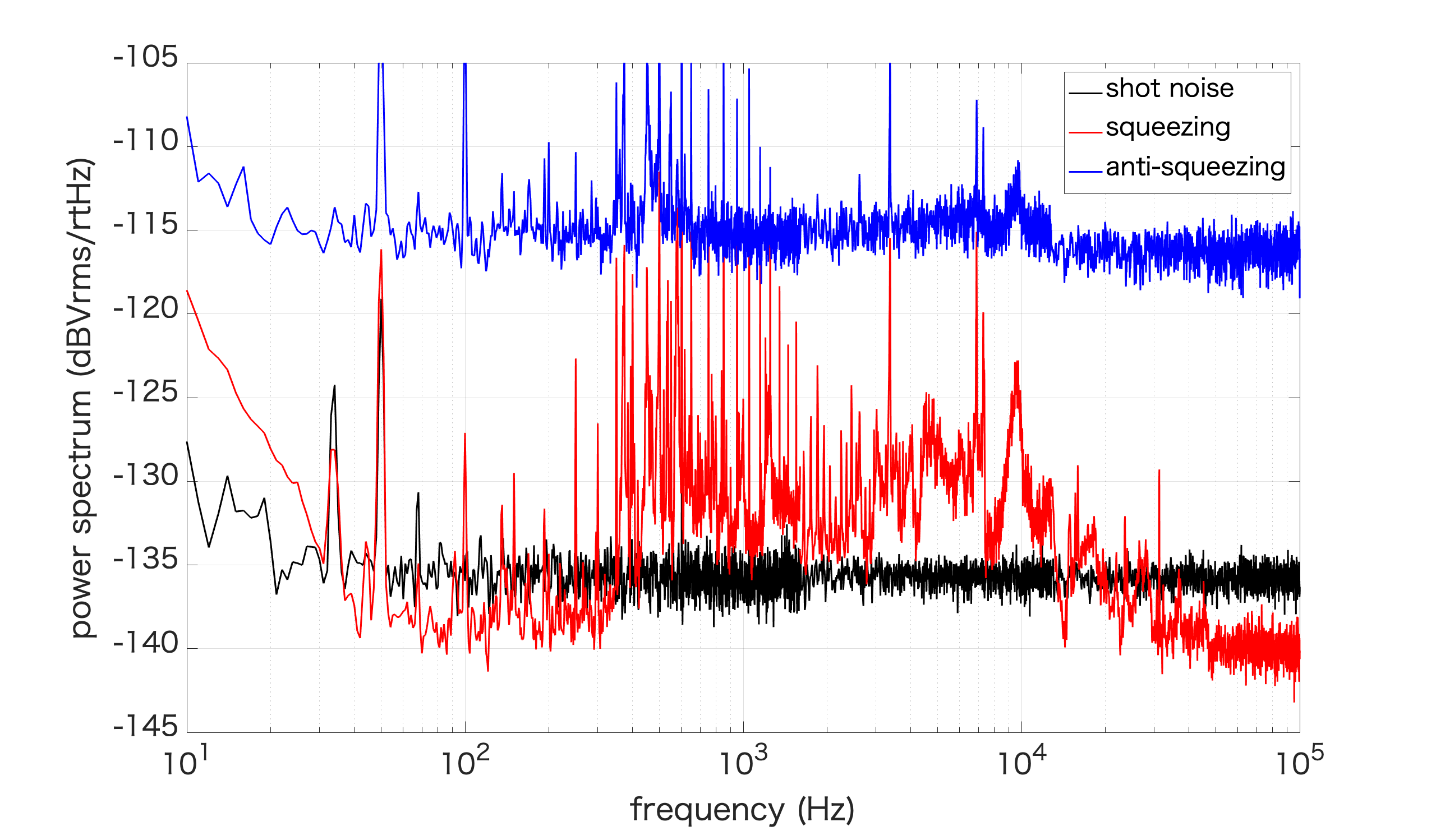
Then we measured squeezing with 50mW green (Pic 2) when both CC loops are stable. Squeezing is ~5dB and anti-squeezing is ~20dB. Squeezing spectrum was not very good due to phase noise. We also measured it with 40mW green (OPO:7.169kOhm, PLL:150MHz). Squeezing spectrum is more clear while squeezing level is almost same.
Here I attach the measurement of SHG and GRMC transmission noise spectrum.
The difference is I measured the noise spectrum of SHG transmission at a wrong place. (Actually, I was measuring the locking noise of SHG in the entry 1501)
However, we really have a worse GRMC transmission noise. Especially, there are peaks from the 4-10kHz region. They are responsible for the region where we have more noise in the squeezing measurement.
I will try to understand why there is a factor between the old and new measurement.
Aritomi and Yuhang
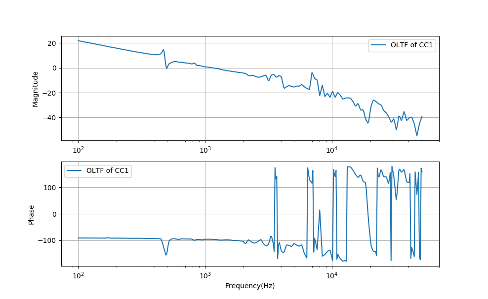
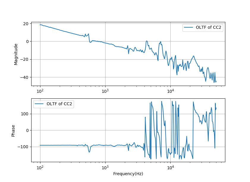
We measured the open-loop transfer functions of CC1 and CC2 yesterday.
We could see from these two figures that 0dB line cross 500Hz and 7kHz for CC1. While 0dB line cross 600Hz, 4kHz and 7kHz peaks at the same time for CC2.
These peaks make locking not easy to achieve. We are thinking about the following things to try:
- to dump resonance by putting rubber
- to use a notch filter to not excite the resonance
- to glue PZT and mirror on the phase shifter
I tried to improve the lock stability by adjusting the gain of SR560.
However, I could not improve so much.
In the end, the lock last only 0.5sec.
So we need circuits for feedback control to achieve stable lock.
Anyway, we can lock the laser to temporal silicon cavity.
To confirm if we have more green phase noise(free-running), I performed the measurement of noise spectrum of SHG and GRMC transmission again.
The comparison is with entry 1276.
We could see we have much more noise now!
Add some points,
- We observed the unstable lock of green phase. And I think it is related to the unstable of squeezing measurement.
- From the phase control behavior, the phase noise(free-running) seems to be higher than before. Need to be confirmed.
- The green phase lock has two main resonance 500Hz and 7kHz. In the beginning, we could find a gain region between these two oscillation and lock green phase. But at the end of yesterday, we couldn't find this region when we change the gain of control servo.
- The error signal for the green phase lock usually change. As pointed out by Aritomi-san, once it is due to the misalignment of green(green power was changed). Actually, we observed a second change of error signal of green phase lock. We check PLL lock, green power(also GRMC alignment), OPO temperature. But they were fine. We should use more time to investigate what makes it change and try to avoid it.