NAOJ GW Elog Logbook 3.2

Today I did alignment work to see the flash of transmitted beam using PD.
I though that PD detected transmitted beam, but it turned out that it was scattered beam...
Then I re-aligned so that the reflected beam reach to FI, and scanned laser frequency with monitoring reflected beam.
At that time, the reflcted beam power was fluctuated.
Actually, it was caused by vibration of cryostat chamber.
So far I have used long pedestal to hold silicon mirrors, and this may affect the vibration of cavity.
Using fixed spacer may reduce the vibration effect, but it might be better to consider about vibration isolation system.
I installed a PD for monitoring transimtted beam of optical cavity with one STM. (forgot to take a photo...)
Though the transmitted power is very weak, the PD detects the transmitted beam.
Then I did alignment and scanned the laser frequency.
However, I have not seen any fringe so far.
I will continue to align the beam with scanning laser frequency and try to find good alignment.
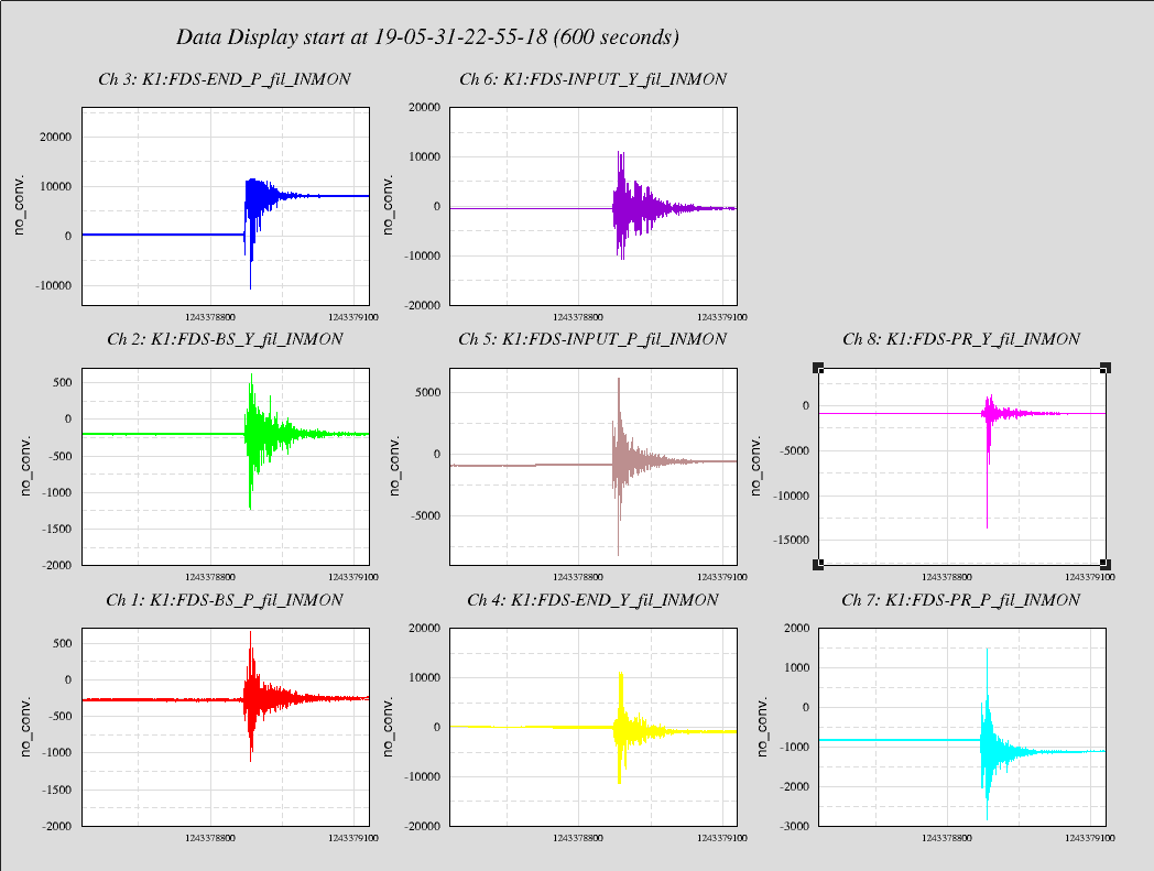
Taking advatage of the the DAQ I playbacked the data and check the oplev signal during a 4.9 Earthquak occured in Chiba prefecture, last saturday.
https://earthquaketrack.com/quakes/2019-05-31-22-58-08-utc-4-9-20
The EQ is cleary seen by all the sensors. Some dof ( in paricular PR and END pitch) didn't go back to the original position.
The data on DAQ are referred to UTC but the time of standalone PC is not well sincronized (about 3 min ahead the correct one).
Chien-Ming, Yu-Hang,
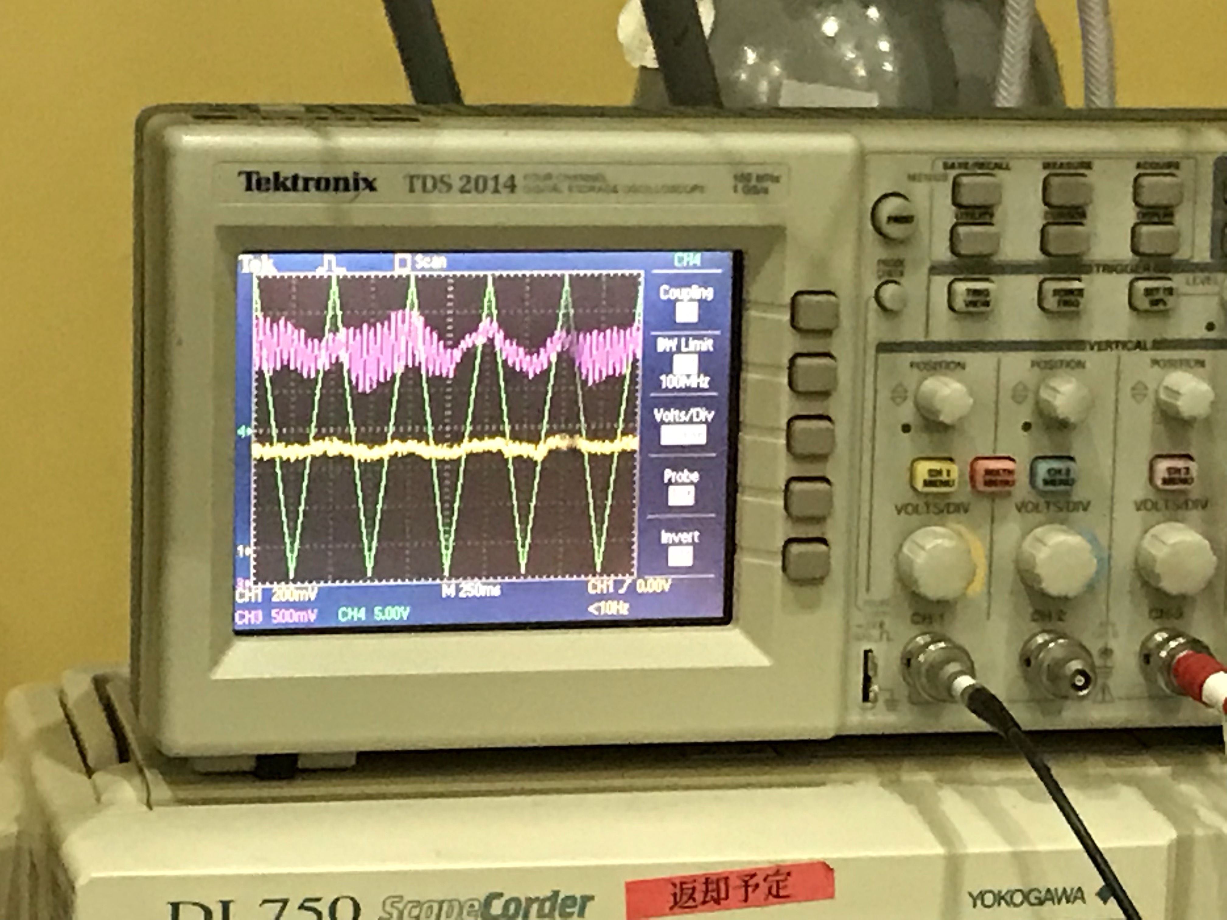
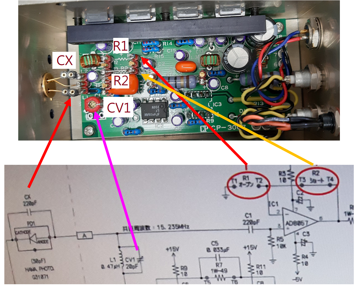
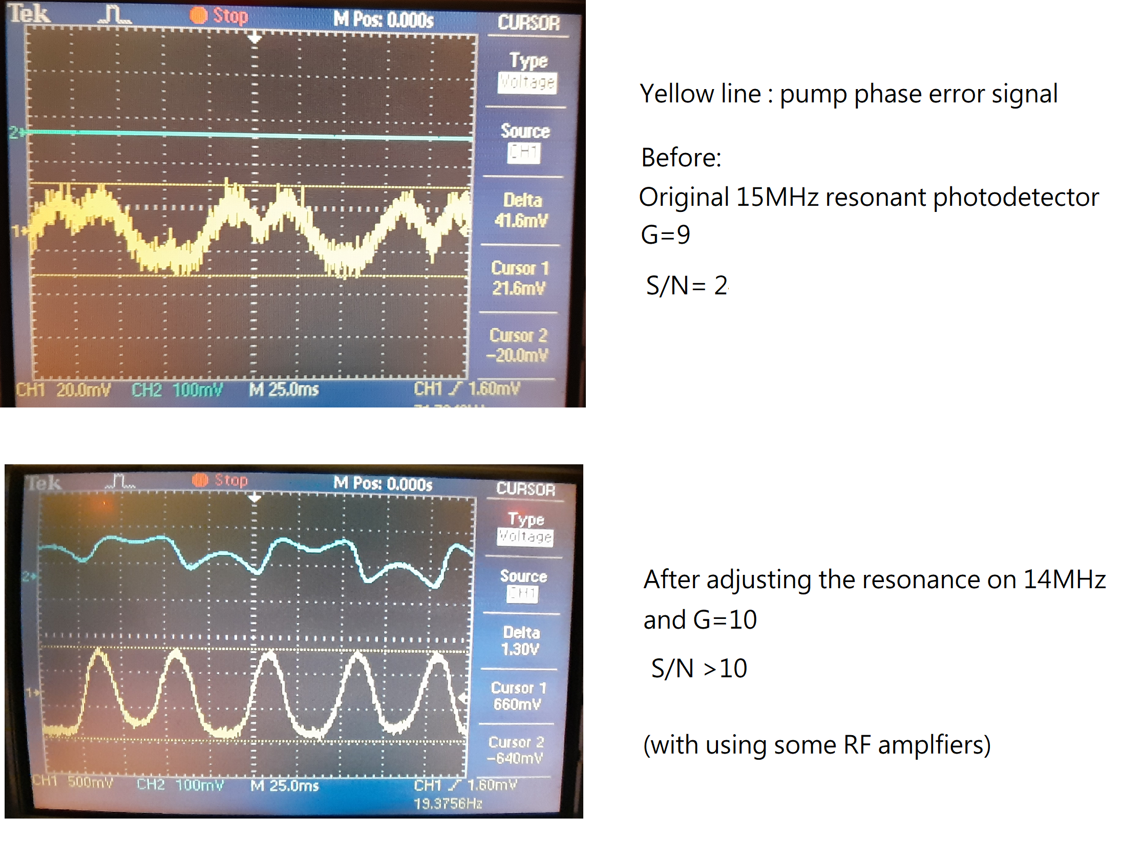
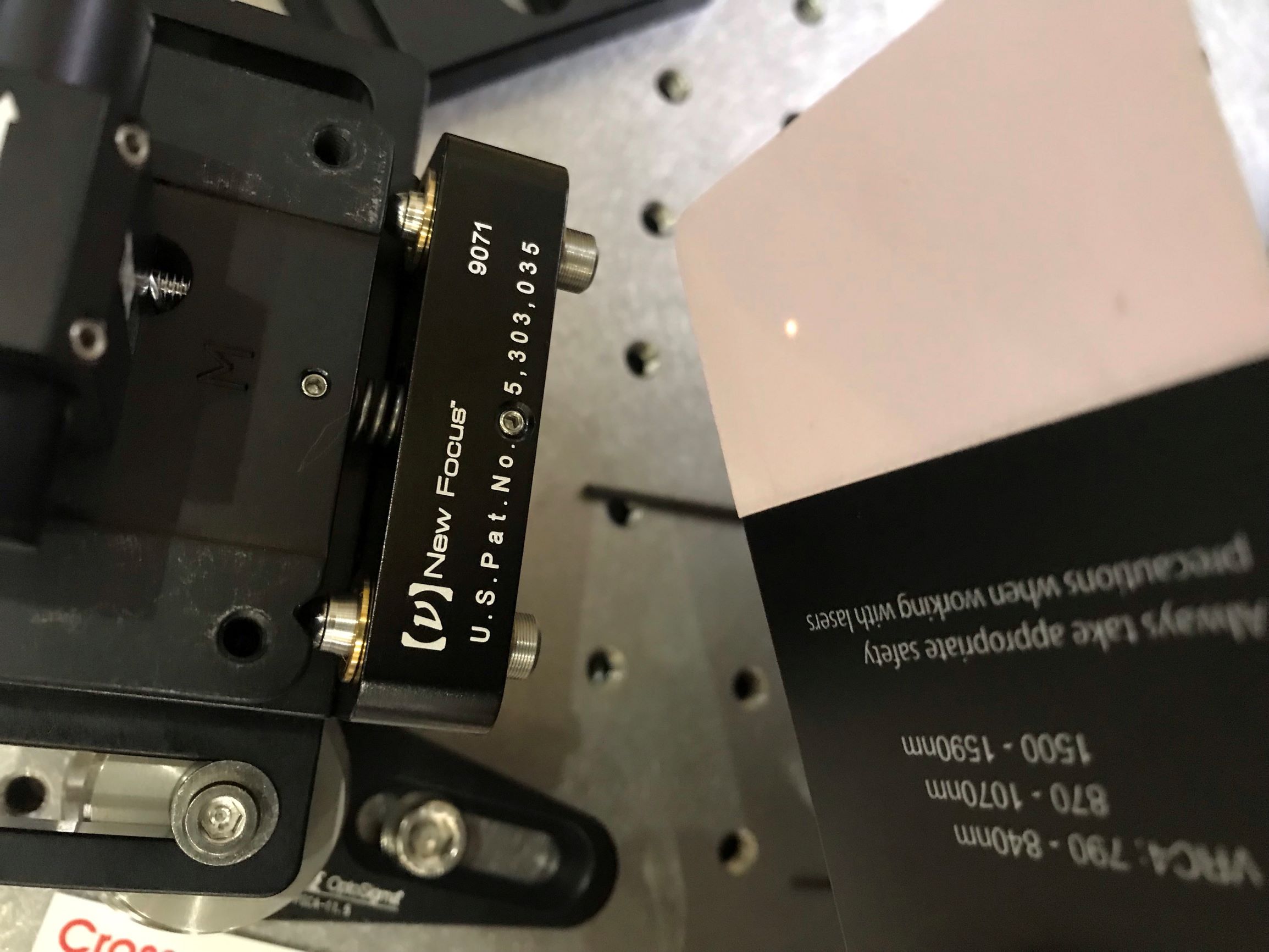
We want to reduce the coherent noise coupled into the homodyne by reducing the intensity of CC beam entering the OPO. However, this action will cause the demodulation 14 MHz error signal (for coherent control of the pump beam phase) to become smaller. So, we tried to increase the gain of the photodetector at 14MHz by changing the capacitor CX and the amplifier resistors R1, R2, see Fig.1.
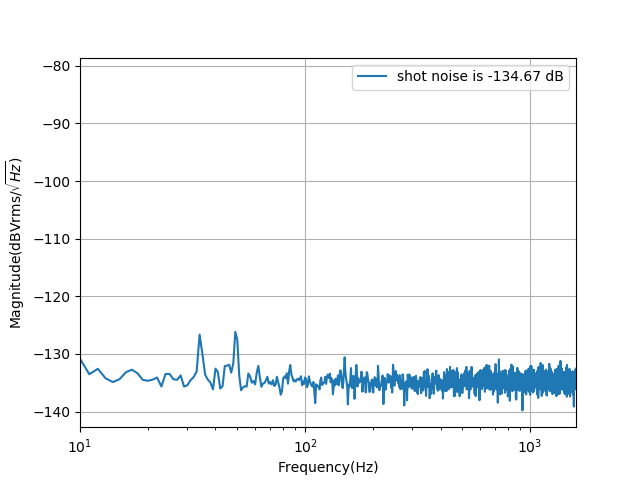
We let the capacitor CX become a plug-in base and test some combinations of capacitors. Currently we find the biggest signal at 14 MHz when using CX as 150pF+33pF. What is puzzling is that when we replace this combination with a single 180 pF capacitor, the signal is reduced by 8 dB on the spectrum analyzer. So, we are now using 150pF+33pF, and R1=500 ohms R2=5k ohms. The S/N now is improved 5 times more as shown in Fig.2.
I installed another silicon mirror inside the cryostat.
Then I did rough alignment of input beam with 2 STMs and the reflected beam reached to FI.
Tomorrow, I will scan the laser frequency and try to find transmitted HOMs.
Yuhang and Chien-Ming
As we said before, we need a better PD for the coherent control1 lock. (PD set at OPO reflection) So we talked and tested several things.
1. Change the amplification factor of the op-amp. We tried two combinations of (500Om, 50kOm) and (500Om, 7.5kOm). For the first combination, we tested the signal, but the amplitude and SNR are the same as before. While for the second combination, the amplitude is smaller while the SNR is a bit better.
We checked the spec of AD8057. The maximum gain we should give for this op-amp is 10. The further increase of the gain will degrade the bandwidth. And this is exactly what we see for increasing further the amplification factor.
It seems that we are also reaching the saturation current of the op-amp.
2. We also tried to use the RF amplifier, because maybe there is an optimal input level for the mixer to make it work better. But it seems RF amplifier increases both signal and noise.
3. We also tried to change the capacitor of the PD circuit. But we are still trying.
[Eleonora P, Yuhang]
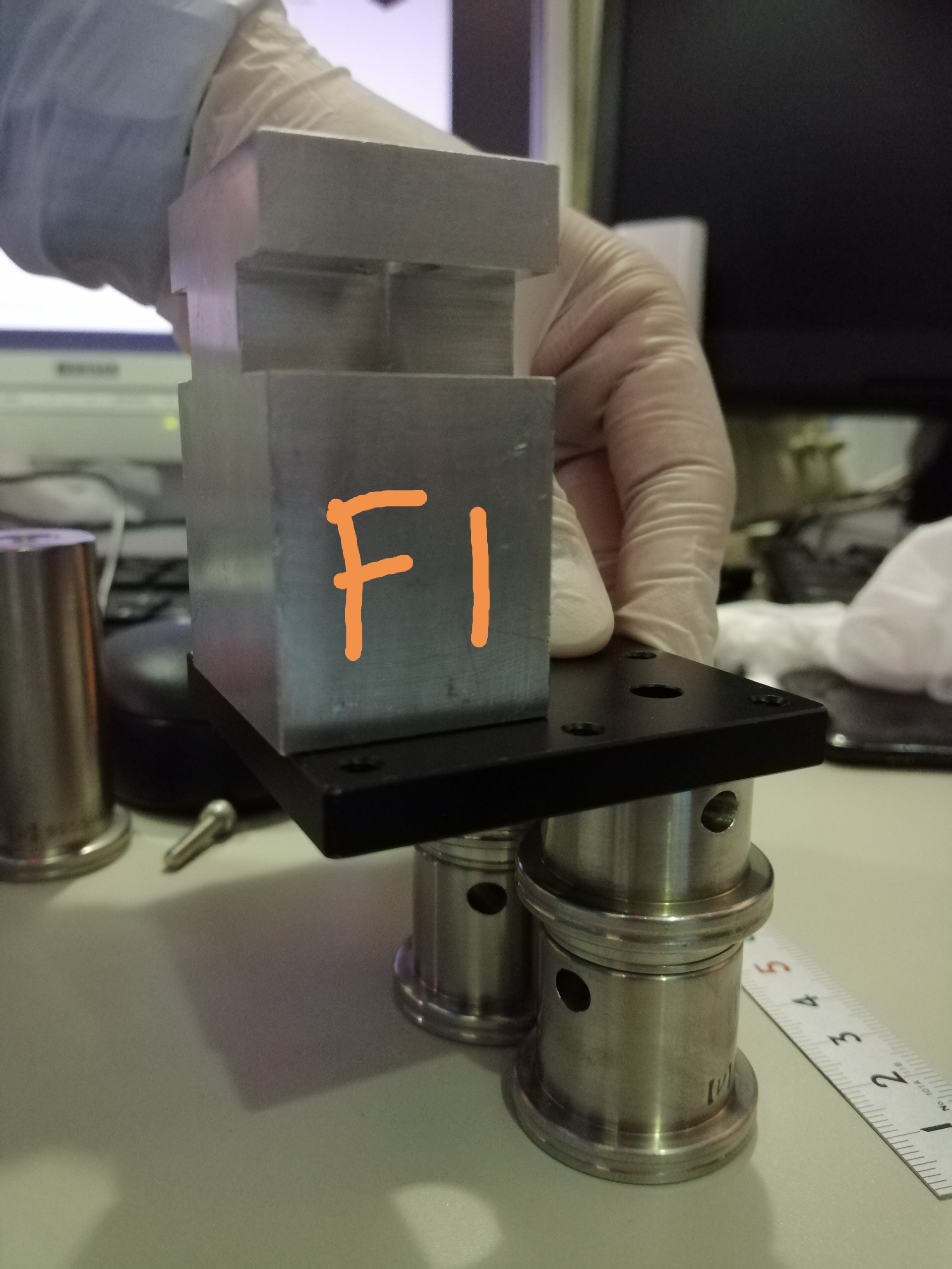
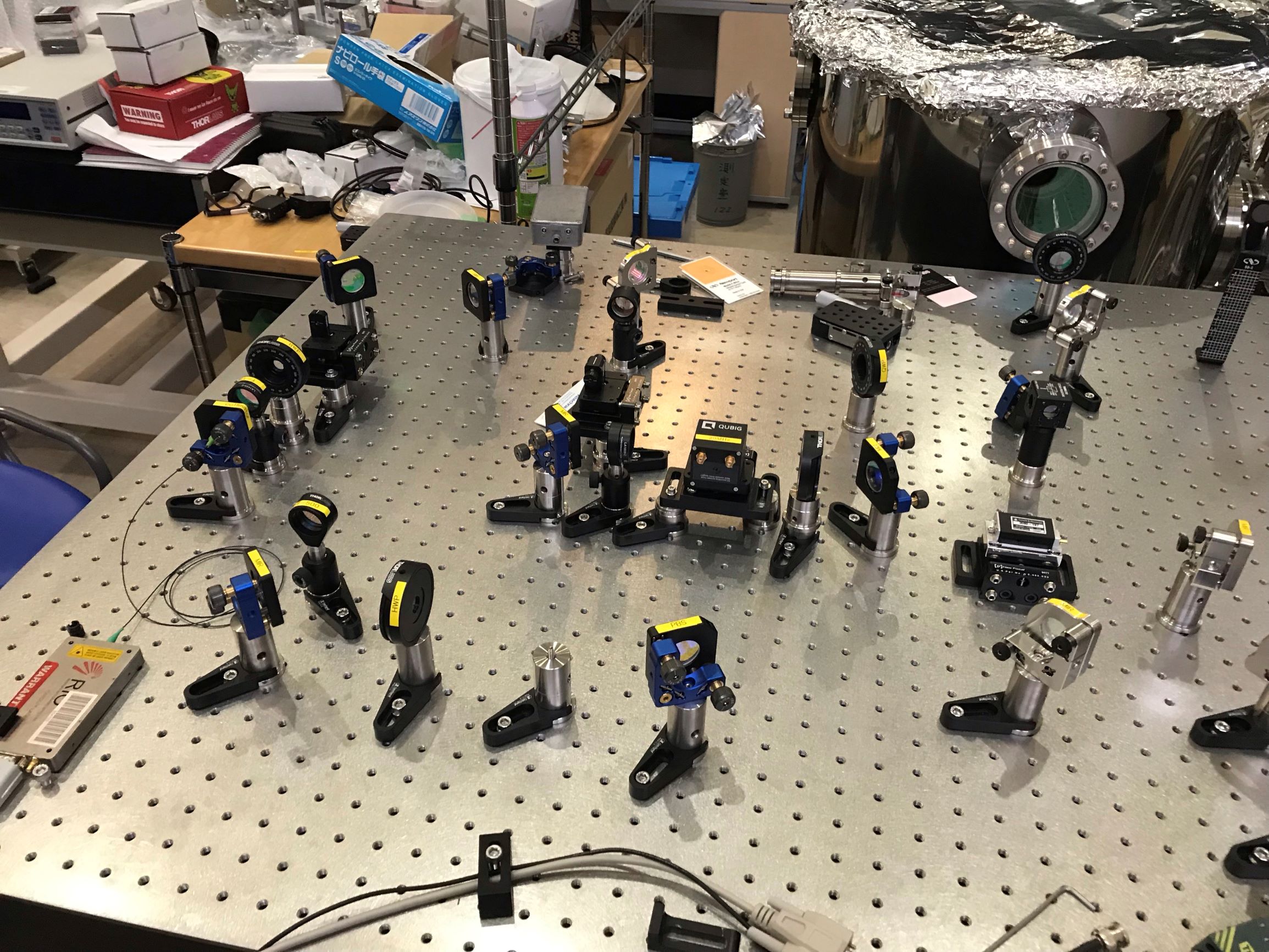
We replaced the FI's stage along the green path, after a hole has been drilled on it as explained in entry #1367.
In fig.1 the picture of the stage on the bench.
I installed one silicon mirror, which was labeled "No.1", inside the cryostat and did rough alignment.
Then I measured beam profile for mode matching.
Today, I re-installed some optics for higher-order-modes.
I wanted to put a iris for the mark of alignment, but I could not find it...
From tomorrow, I'm going to install silicon cavity inside the cryostat.
I changed optical layout to achieve better alignment.
I will update the schematic figure of optical layout later...
Anyway, the alignment seems ok so far.
As shown in entry #1363, the error on the beam waist position is large ( around 8%).
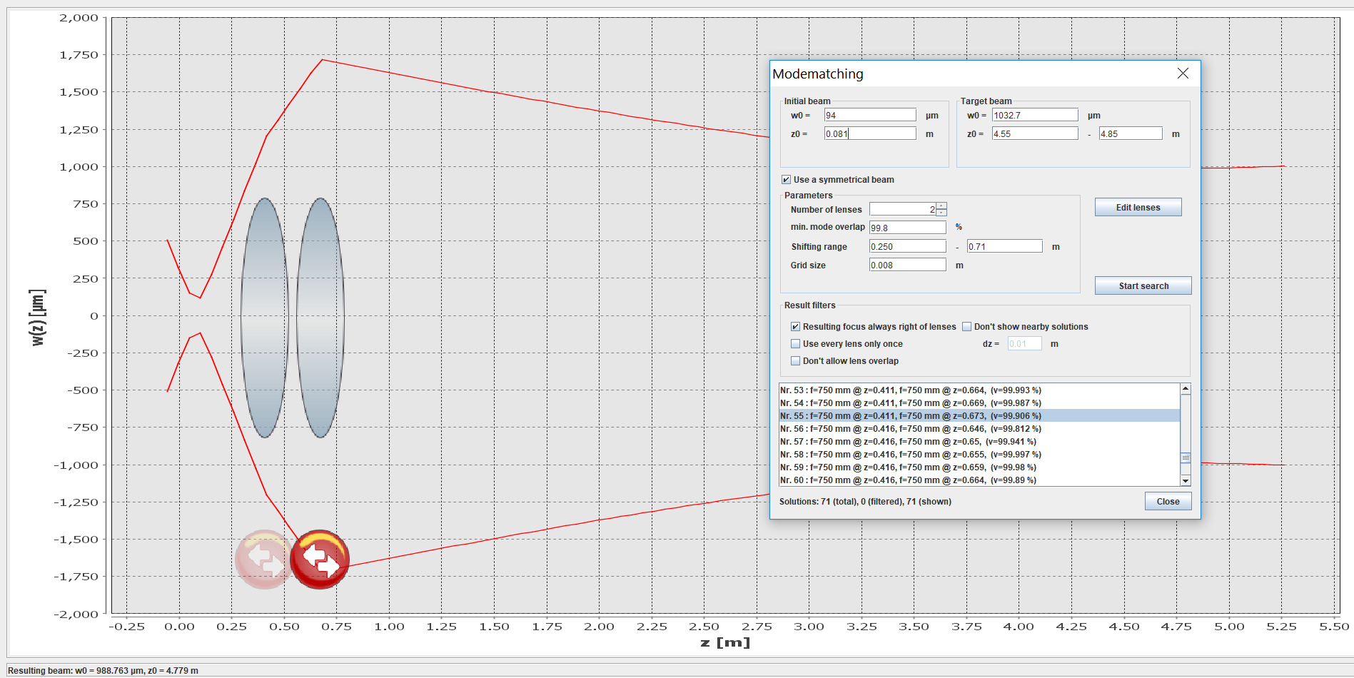
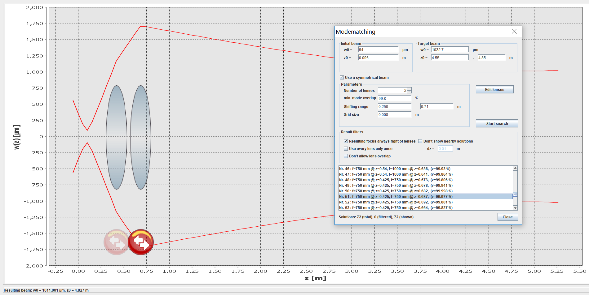
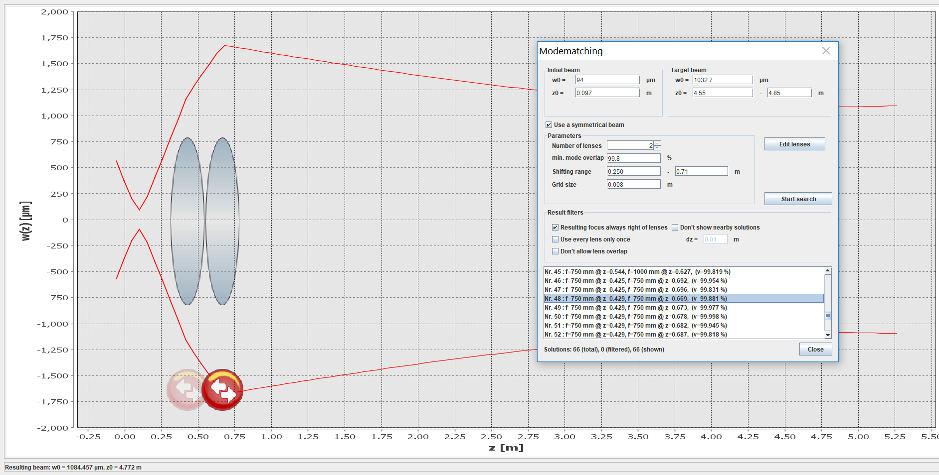
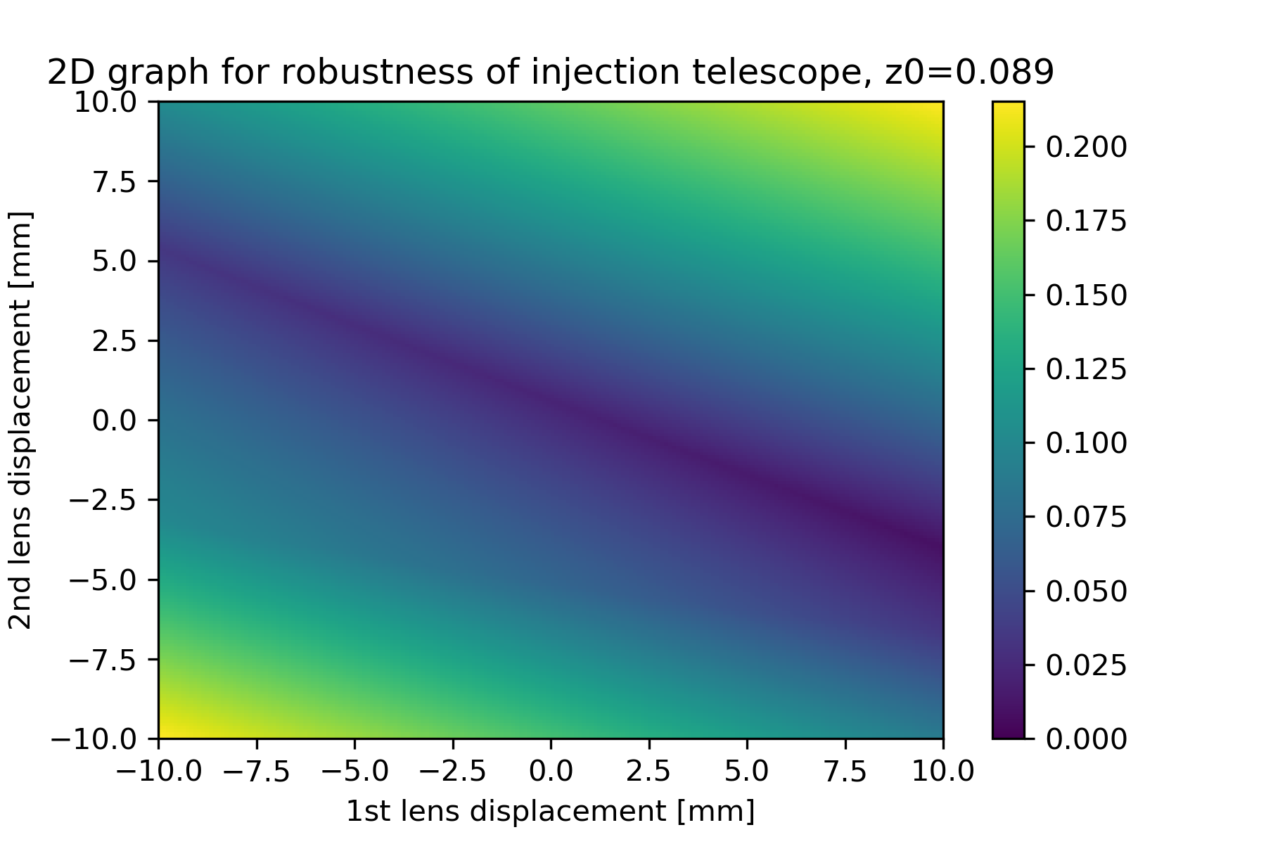
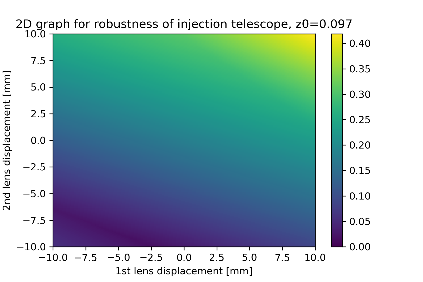
I checked if the solution #3 of entry #1366 would be good also considering the border positions of beam waist in the error interval, running again the simulations (fig 1, 2, 3) and analyzing the robustness on Python.
Both focal lengths are 750 mm.
I summarize the results in the following table:
| z0 (m) | pos lens 1 (m) | pos lens 2 (m) | pos lens 1 at min mismatch (m) | pos lens 2 at min mismatch (m) | min mismatch (%) |
| 0.089 | 0.420 | 0.673 | 0.424 | 0.673 | 0.9 |
| 0.081 | 0.420 | 0.673 | 0.4276 | 0.683 | 1.8 |
| 0.097 | 0.420 | 0.673 | 0.410 | 0.6755 | 1.6 |
where the positions of the lenses is referred to the PBS after the OPO.
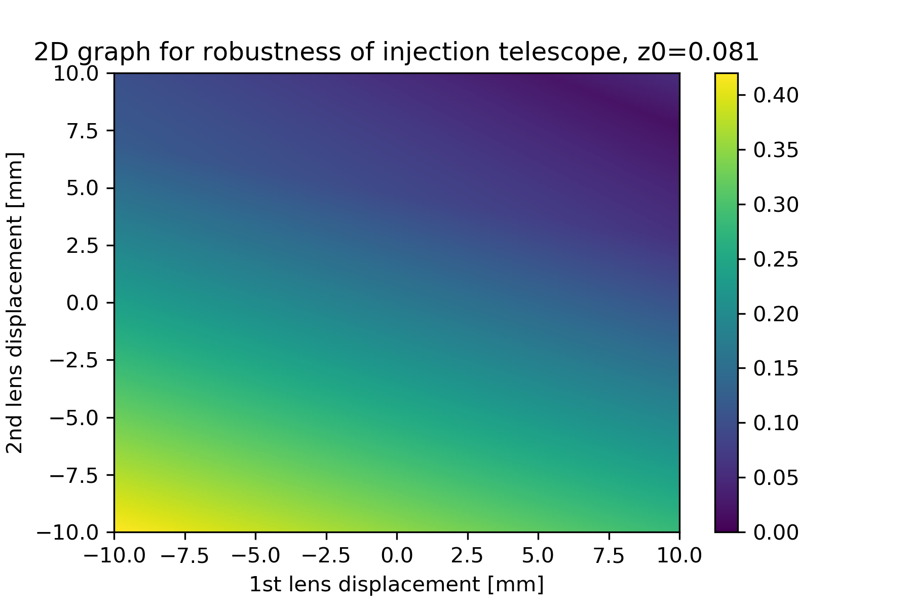
I computed on Python the position of the two lenses corresponding to the condition of minimum total mismatch.
In fig. 4, 5 and 6 are shown the robustness of the telescope with z=0.081 (min position), 0.089 (real position), 0.097 (max position), that are still pretty good (less than 10% mismatch).
[Yuhang, Chien-Ming]
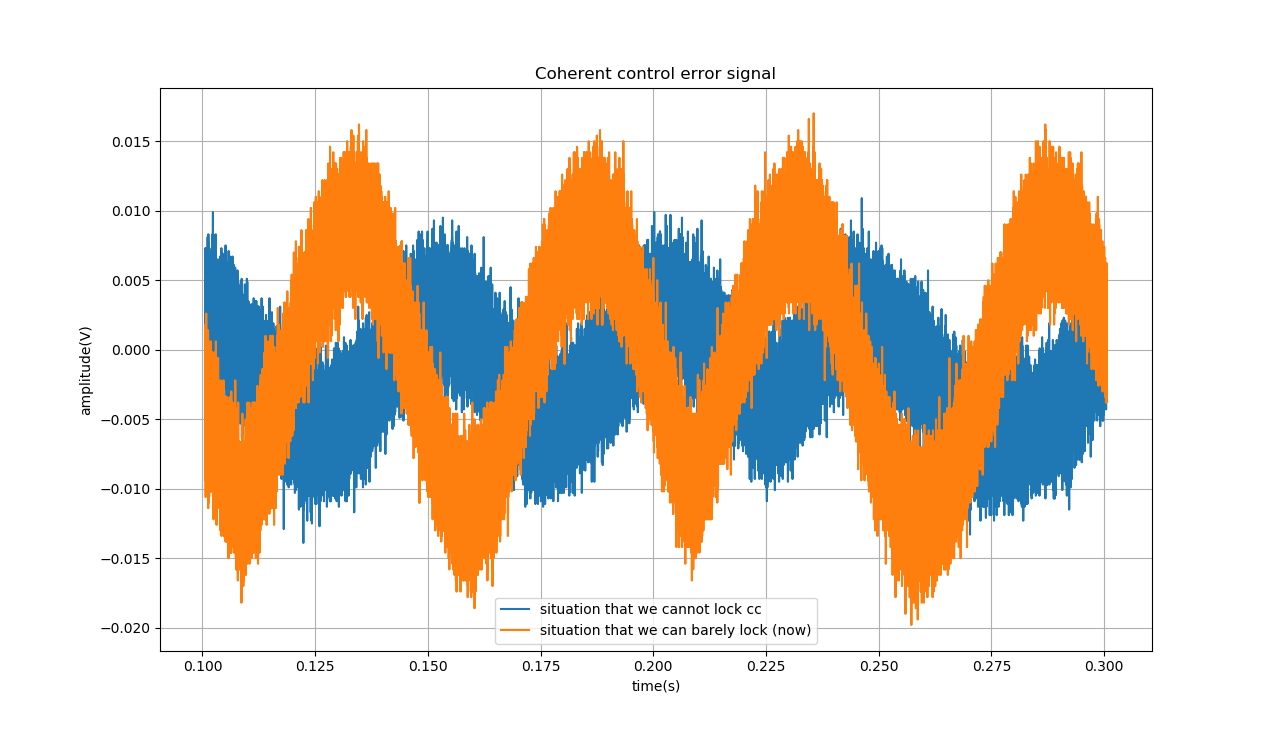
Today we tried to decrease CC laser power. But when we just decreased it to half, we couldn't lock the CC1 loop.
The cc error signals that we can use to lock and cannot be used to lock are attached in Fig1.
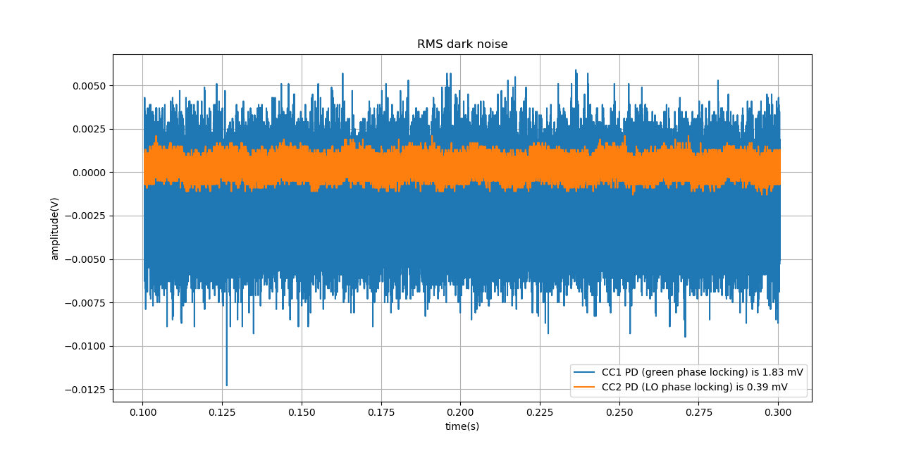
The RMS dark noise for CC1 and CC2 PD is measured and attached in Fig2. We can see that the CC1 PD has RMS dark noise almost 5 times higher than CC2 PD.
We also suspected that this noisy PD for CC1 locking brings also phase noise.
I installed a FI for TEM00 PDH locking, and confirmed that one can pick off reflected beam with simple setup (QWP and mirror).
The attached picture shows the reflected beam picked up by FI.
Then, I continued the installation of optics.
However, I found that the height of FI was not good, which is not the one I mentioned but already installed one before.
So I modified the alignment.
Actually, the beam height is still higher than the target height, though I cannot adjust anymore.
So I am planning to install STMs in front of the EOM, which can adjust the beam height.
[Yuhang, Chien-Ming, EleonoraP]
After the improvement of homodyne suggested by Chien-Ming, we measured squeezing again.
This time, we could see only two peaks for homodyne shot noise limited down to 10Hz when LO incident. The 34Hz peak is related to some unknown device(maybe air-conditioner). The characterization of this 34Hz peak is done by Federico and Irene. While another peak is a 50Hz power line. (We didn't perform a low-frequency high-resolution measurement, we may see some peaks at low frequency in that case. We will do it soon.)
For SQZ, we could see the noise floor(5.5dB SQZ) down to 10Hz with several narrow peaks. But notice that now there is still 2.4mV DC signal(for SQZ path) not balanced on homodyne. We could possibly improve CMRR for SQZ path soon.
For anti-SQZ, we could see 13.25dB. And it is also very flat.
The result is shown in the attached figure. We didn't pay attention to the measurement bandwidth of anti-SQZ and LO-shot noise. But we may do it again after the refinement of BAB balance.

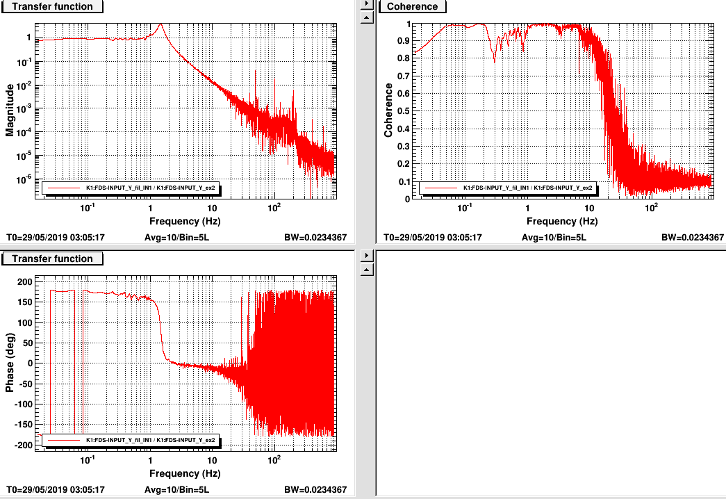
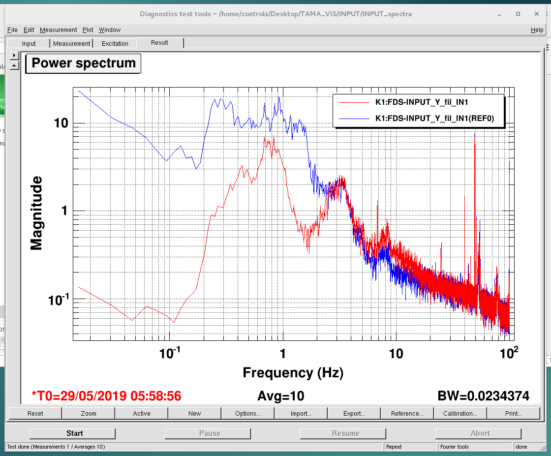
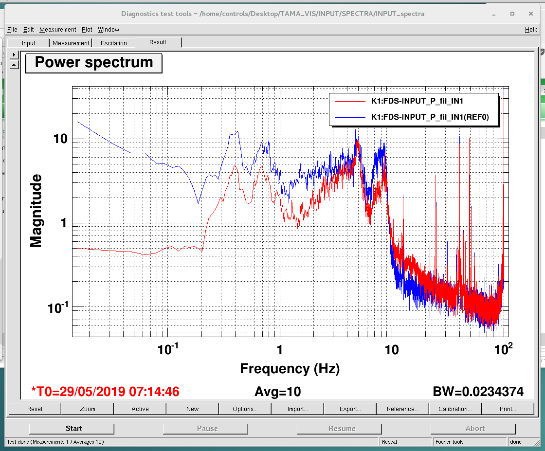
The local controls for the input mirror have been implemented in the new DGS.
As usual, we amplified and filtered the PSD signals for pitch and yaw with a SR560 (2nd order lowpass, cutoff 100 Hz, gain 100)
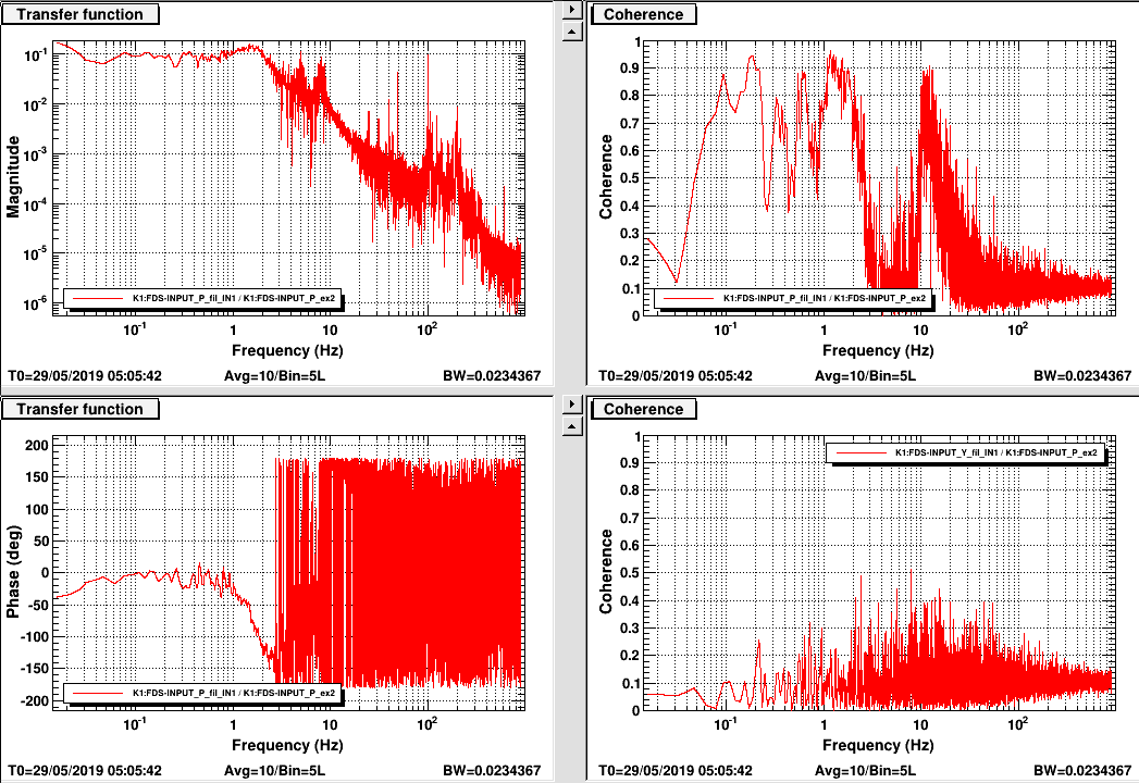
TF for yaw and pitch are reported in pic 1 and 2. (injected noise: 5000 and 7000 counts respectively)
As for PR and BS the pitch TF and coherence is not very good.
Comparison between open and closed loop spectra are shown in pic 3 (yaw) and 4 (pitch)
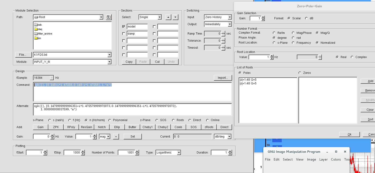
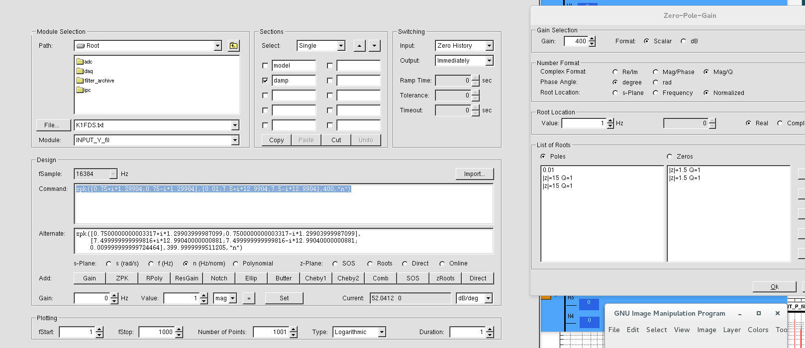
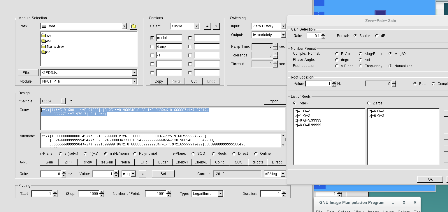
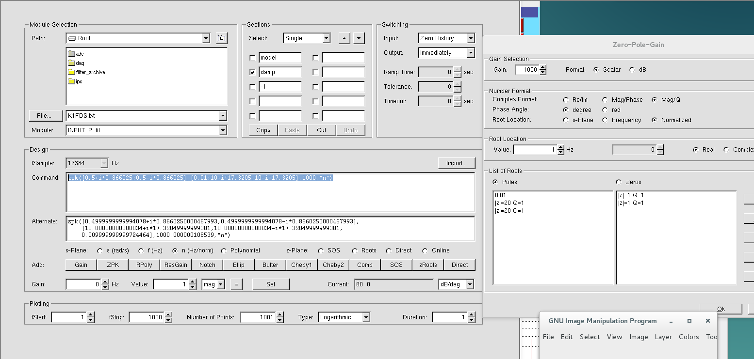
I attach the filters values (model and damp for both yaw and pitch):
Fig 5 yaw model
Fig 6 yaw damp
Fig 7 pitch model
Fig 8 pitch damp
I will compute the calibration soon.
Chien-Ming, Yu-Hang, and Aritomi
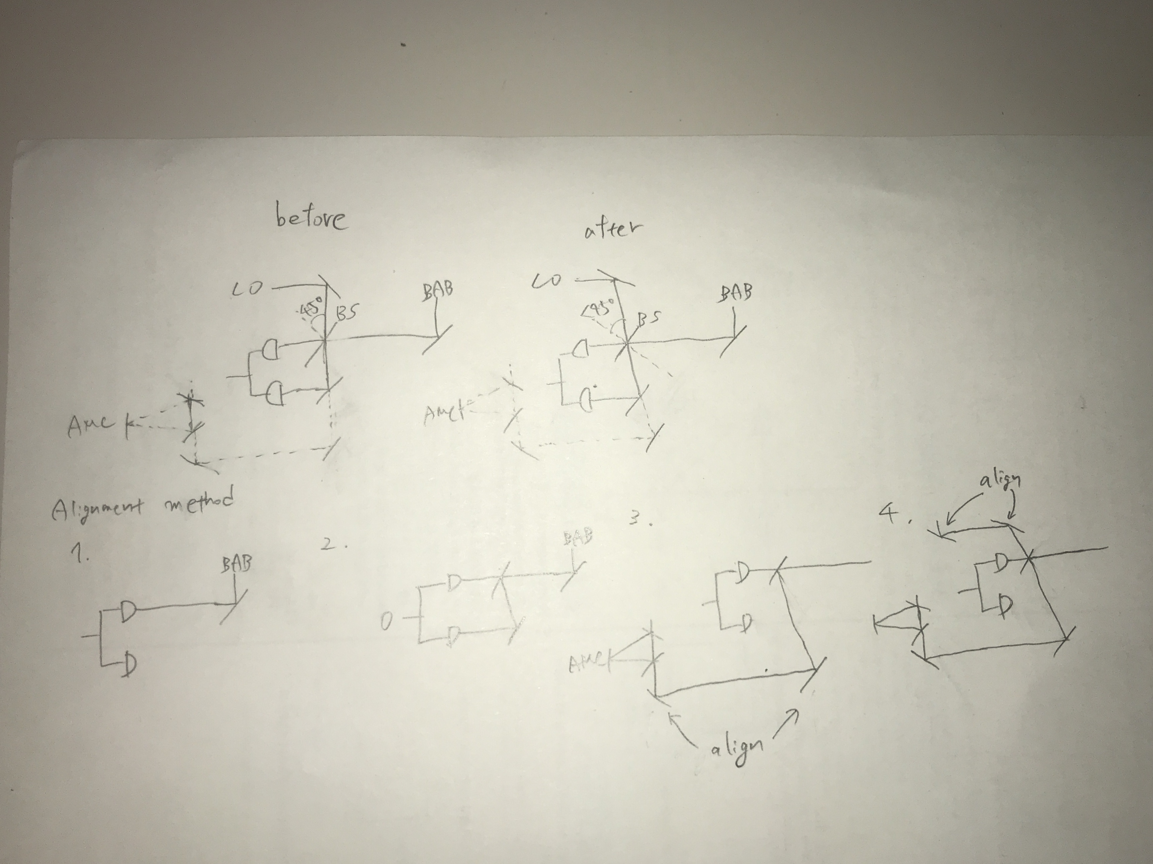
Yesterday we adjusted the BS horizontal angle to make the LO beam reach the DC balance at homodyne detector. We measured the CMRR, it is better than 80 dB at 1 kHz.
However, in this case, if we let that BAB and LO have a good overlapping, we need to change the optical set up of BAB a lot.
So today we keep the BAB beam in its original condition and adjust the BS angle to make the BAB beam reach the DC balance at homodyne. Then we adjust the LO beam to achieve a good overlapping with BAB beam. In this case, when the BAB is DC balanced, the homodyne DC offset of the LO shows -10mV.
We repeatedly adjust the BS angle and the alignment of both beams a little bit, finally, we make the LO beam become DC balanced and the DC Offset of BAB is 2.4 mV.
Takahashi-san, Sato-san, Tanioka
We removed the 4K shield of cryostat in ATC in order to ship it to KEK.
Some insulator are detached from 4K shield to remove screws.
[Yuhang and EleonoraP]
First we aligned the green beam before PR chamber.
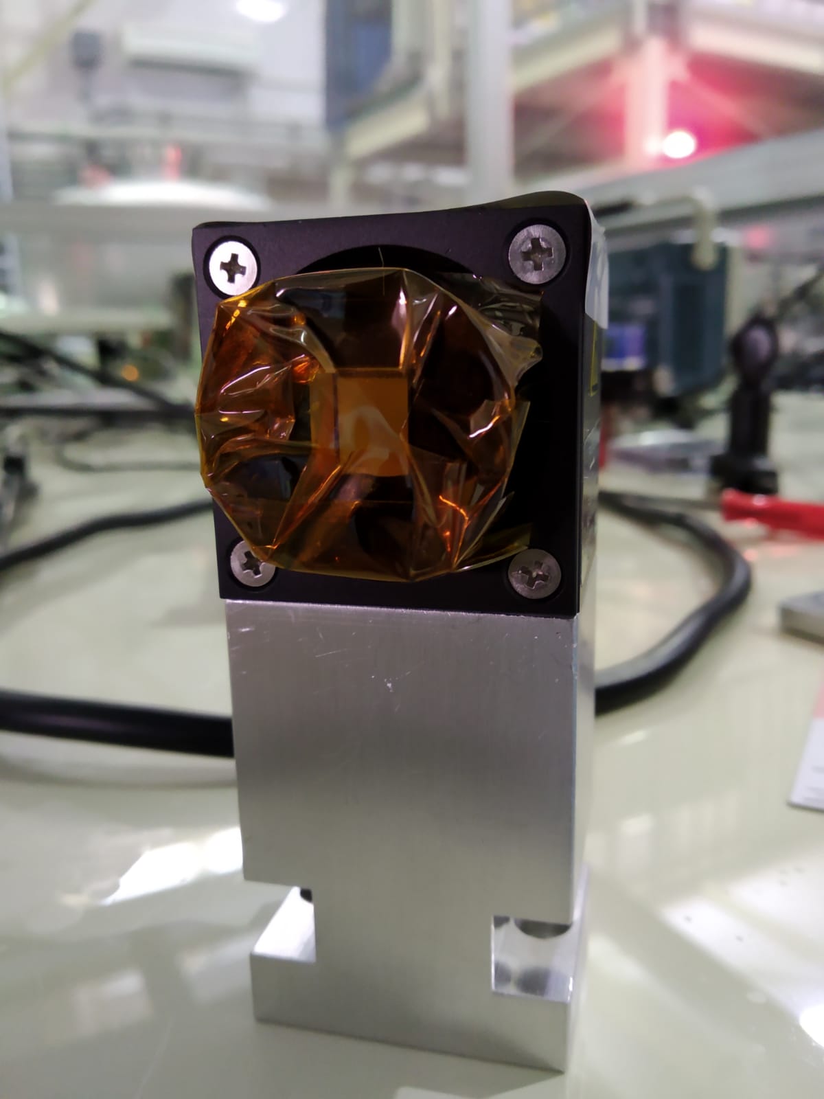
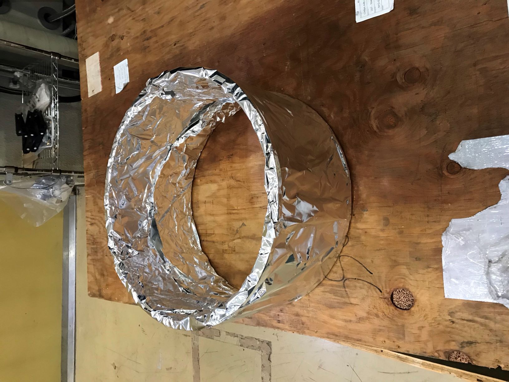
Then we changed the stage of Faraday Isolator with a smaller one, in order to make space for the wind shields. We put some schotch to cover the borders of the FI, to avoid damages (fig 1).
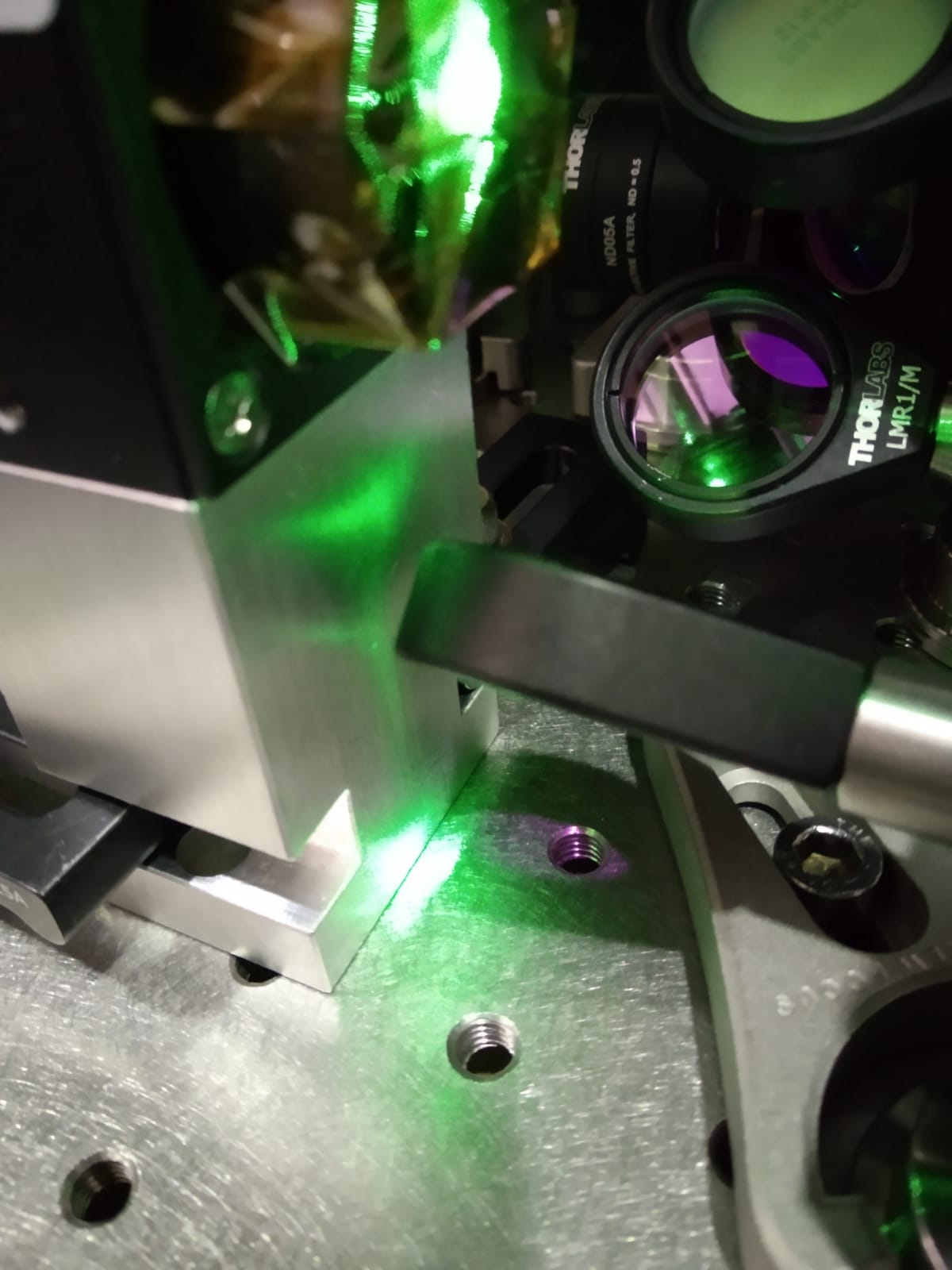
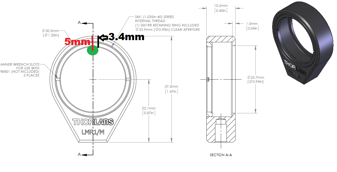
We found a problem: not enough space for the mirror under the FI (fig 2). The black plastic edge of the mirror mount is 3.4mm while the beam reflected by the FI crystal is 5 mm far from the stage edge (fig 3).
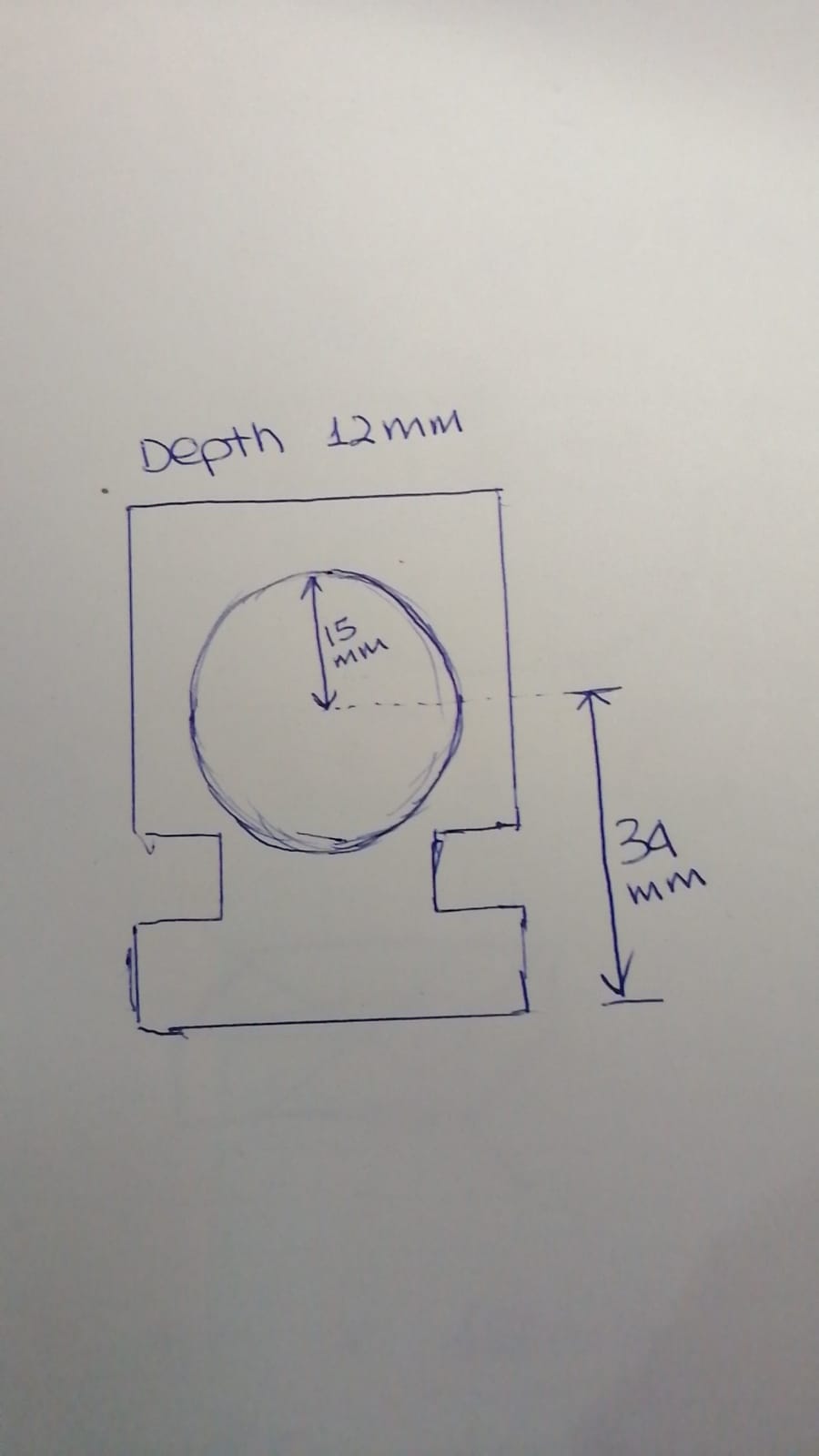
Possible solutions:
1. make a hole in the mount in order to make space for the mirror. Size of the hole: 30 mm (diameter) and 12 mm (depth) in fig 4.
2. build a different stage with other components, in fig 5.