NAOJ GW Elog Logbook 3.2

[Takahashi, Aritomi, Yuhang, Michael]
Since the END picomotor didn't move, we opened END chamber and aligned FC. We aligned PR and BS to make the green at center of GV between input/BS and at the upper left of first target as reported in elog2935. After we scanned BS alignment, we found the beam at second target.
Then we checked the behavior of END picomotor with old picomotor driver by looking at the green reflection from END mirror at the second target. We connected pitch picomotor to motor A and yaw picomotor to motor B. There are two settings of joystick: SET X and SET Y. In SET X, whatever the selected motor, when we move the joystick in X direction, the beam moves in yaw and when we move the joystick in Y direction, the beam moves in pitch. In SET Y, we can select the motor and the selected picomotor can be moved by moving the joystick in Y direction. We don't understand the bahavior of SET X, but we should use SET Y of joystick. We also confirmed that all motors of old picomotor driver are working.
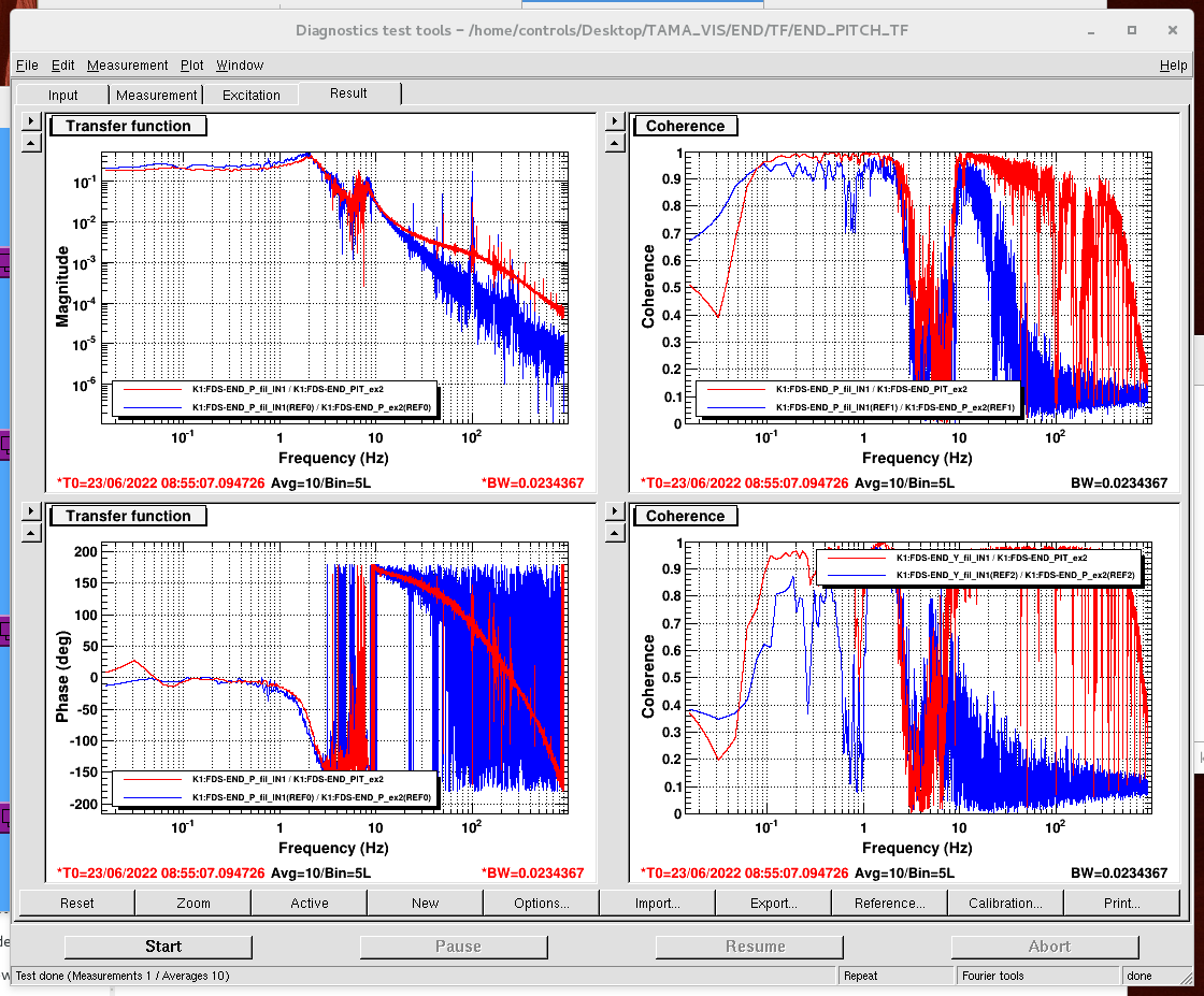
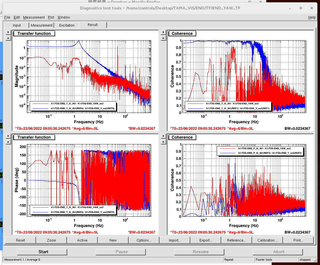
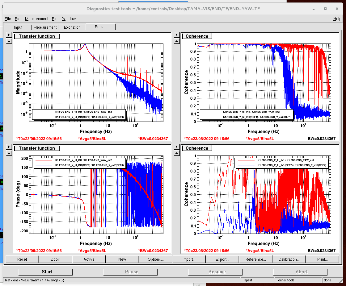
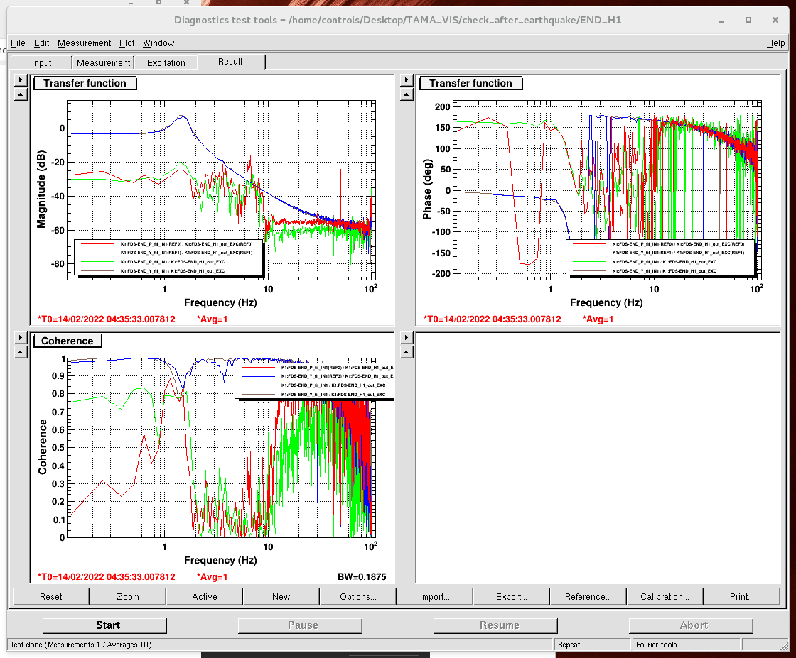
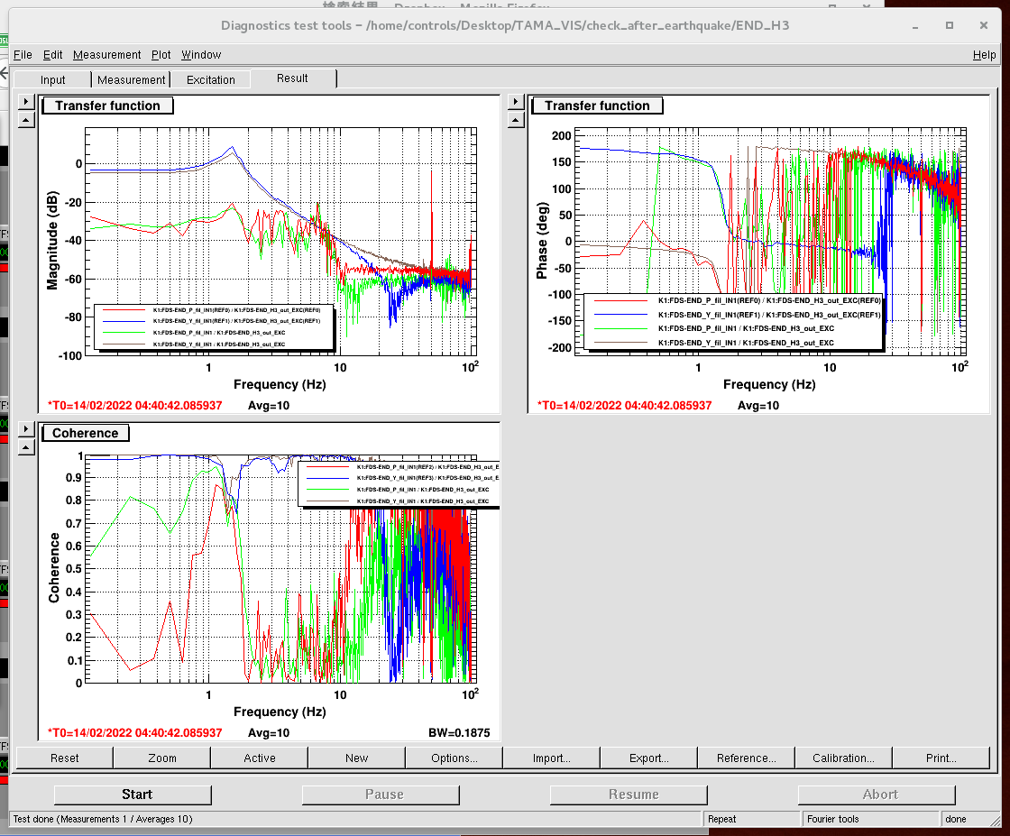
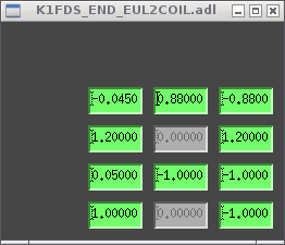
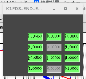
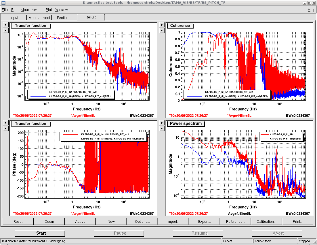
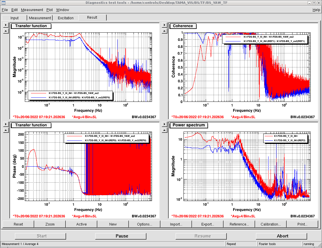
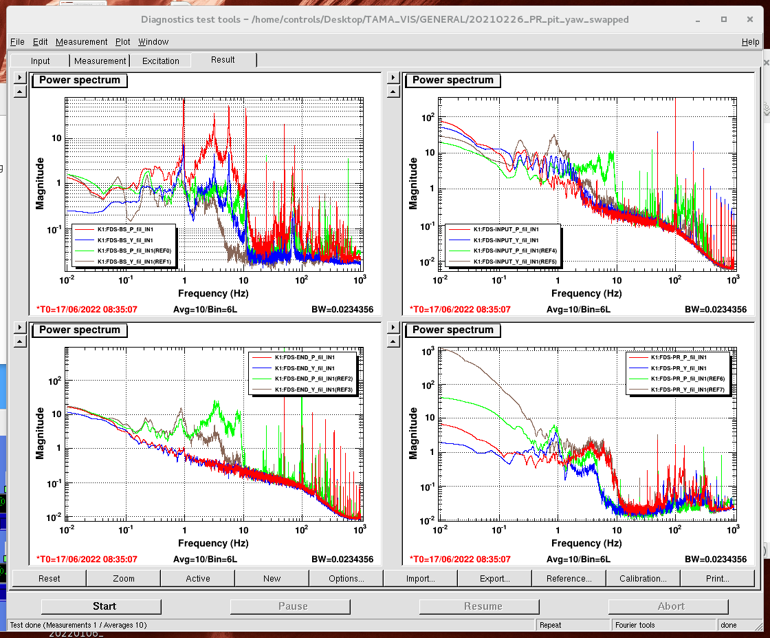
To obtain the END oplev signals, we brought back the Dsub cable from PEM to END oplev signals. We found that when the END oplev beam is blocked, END oplev X and Y show around 2100 and -800 counts, respectively. After we centered the oplev around these values, we checked pitch/yaw TF. The pitch TF was fine (Fig. 1), but yaw TF was strange (Fig. 2). We found that yaw TF becomes fine when we flipped the sign of EUL2COIL matrix for H3 (Fig. 3). When the sign of EUL2COIL matrix for H1 is flipped, the sign of yaw TF is also flipped. We also checked the response of H1, H3 magnets with health check script (H1: Fig. 4, H3: Fig. 5), which also shows the sign of H3 magnet is flipped. This flipping happened when we glued it in elog2900. We flipped all the sign of EUL2COIL matrix for H3 (before: Fig. 6, after: Fig. 7).
Finally we closed the chamber. We will start evacuation tomorrow.
Important note: After we glue the fallen magnet, we should also check the sign of the magnet. If the sign of the magnet is flipped, we need to flip the sign of EUL2COIL matrix for the magnet.
Today I repeated the characterization of an 'unknown sample' (a HWP) using motorized HWP and translation motor.
First, the calibration gave X_cal = 13.3 mm which is compatible with the previous estimation.
Then, I measured the unknown sample retardance to be 0.496 which is expected value.
Next step will be to be able to access photodiode signal on the PC to start the LabView automatization.
Seismic data of KAGRA is under OMC chamber and the microphone is in the IMC refl.
The large peak at one-handed several-tens Hz of the seismic data is the self-noise. (data sheet)
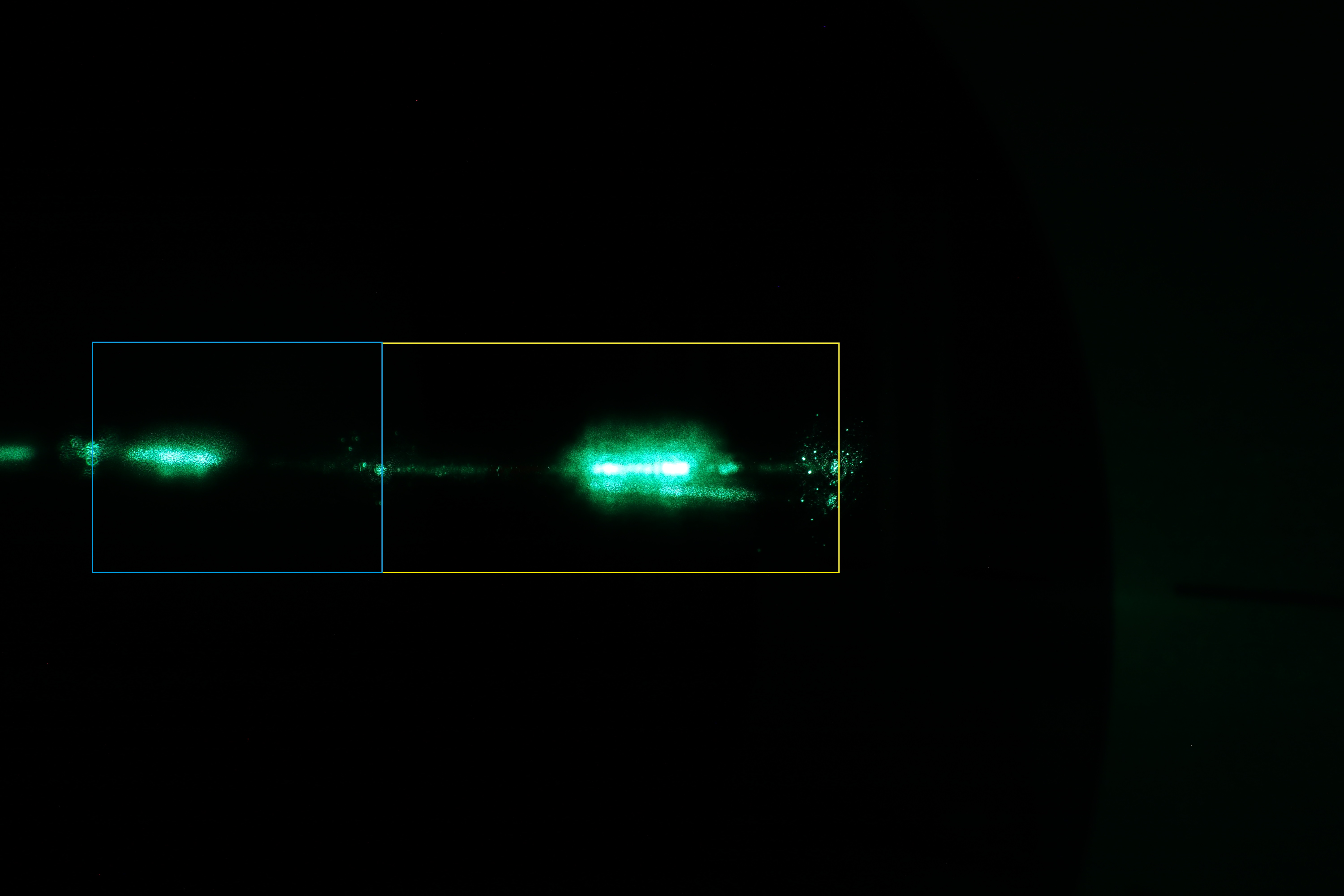
We try to measure scattering of Aztec 3.
We can take a picture of scattering light.
In this figure, scattering light is in the yellow box.(Blue box is reflection light by mirror surface)
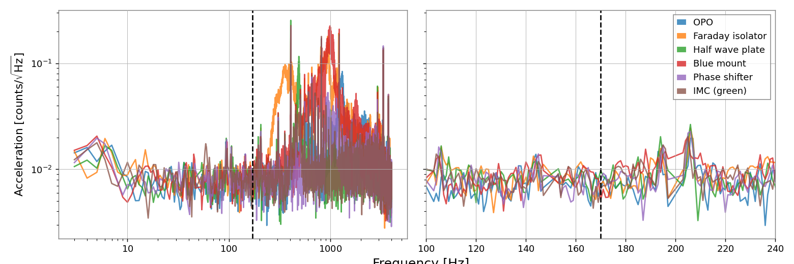
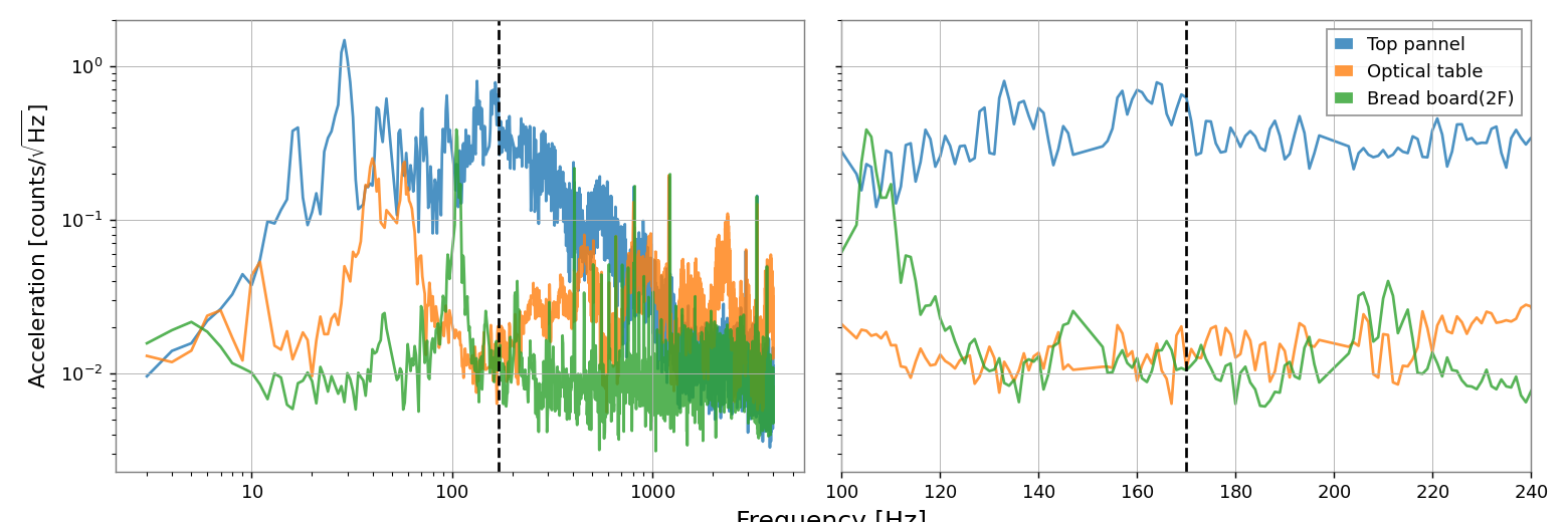
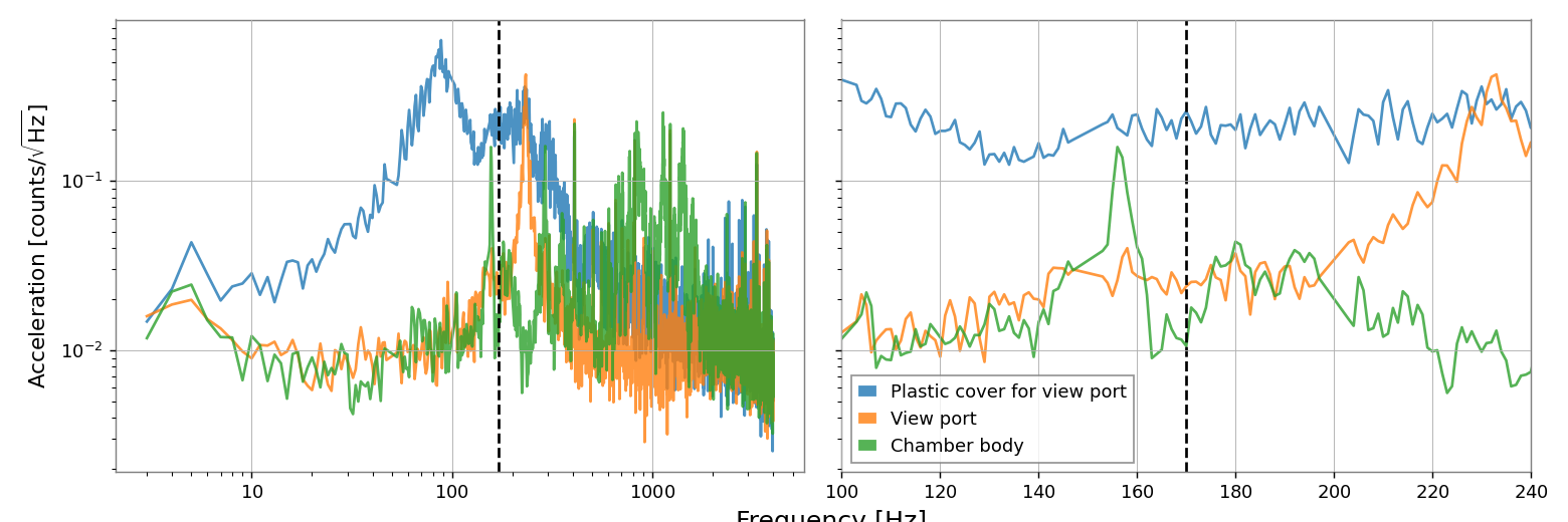
We performed the hammering test for the FC optics, to investigate the origin of the 170Hz noise.
50n Hz peaks are AC power and its harmonics.
The Eigen frequencies of the optics are higher.
The most suspicious object was the chamber.

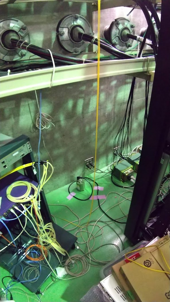
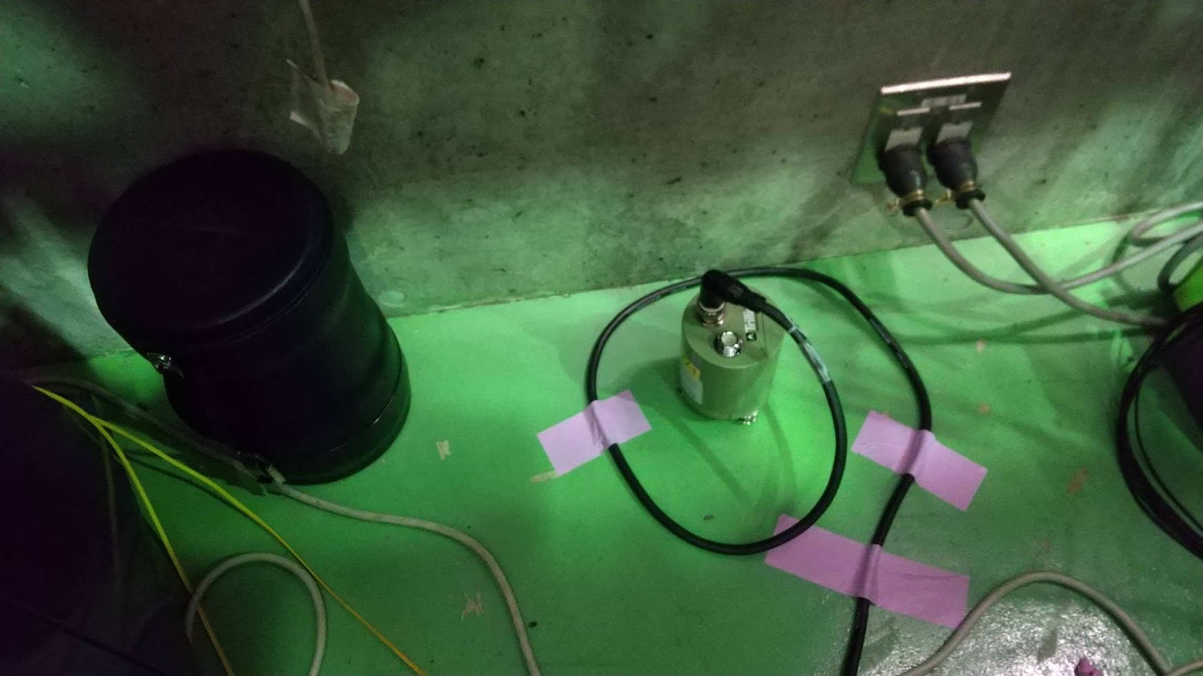
We brought the PEM sensors from KAGRA to TAMA temporally.
* Trillium compact seismometer and its cable
* Whitening filter with DC power supply and D-sub 15pin cable
* ACO microphone, ACO 4ch power supply, and BNC cable
* 3-axis accelerometer and its cable
We connected the seismometer and the microphone to the ADC ports.
* K1:FDS-ADCspear_1_OUT_DQ -> Low frequency microphone
* K1:FDS-END_in_HOR_fil_IN1 -> Seismometer East-West
* K1:FDS-END_in_SUM_fil_IN1 -> Seismometer North-South
* K1:FDS-END_in_LEN_fil_IN1 -> Seismometer Vertical
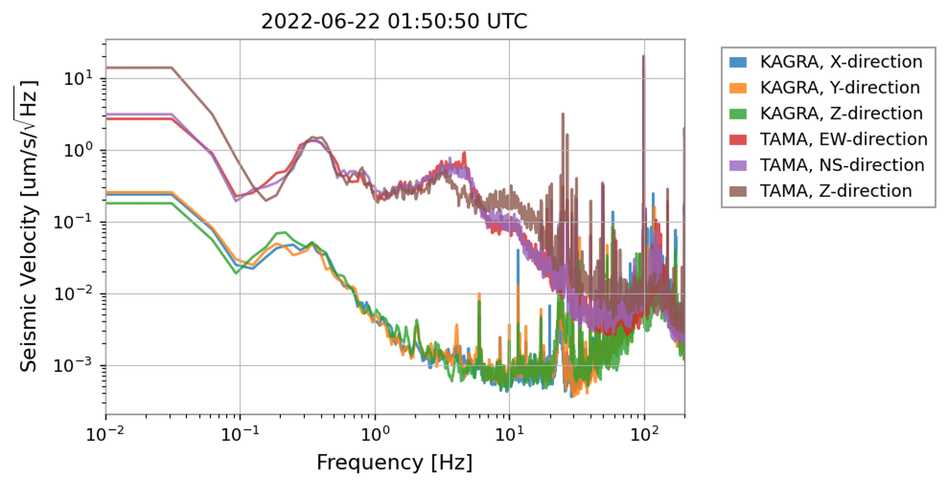
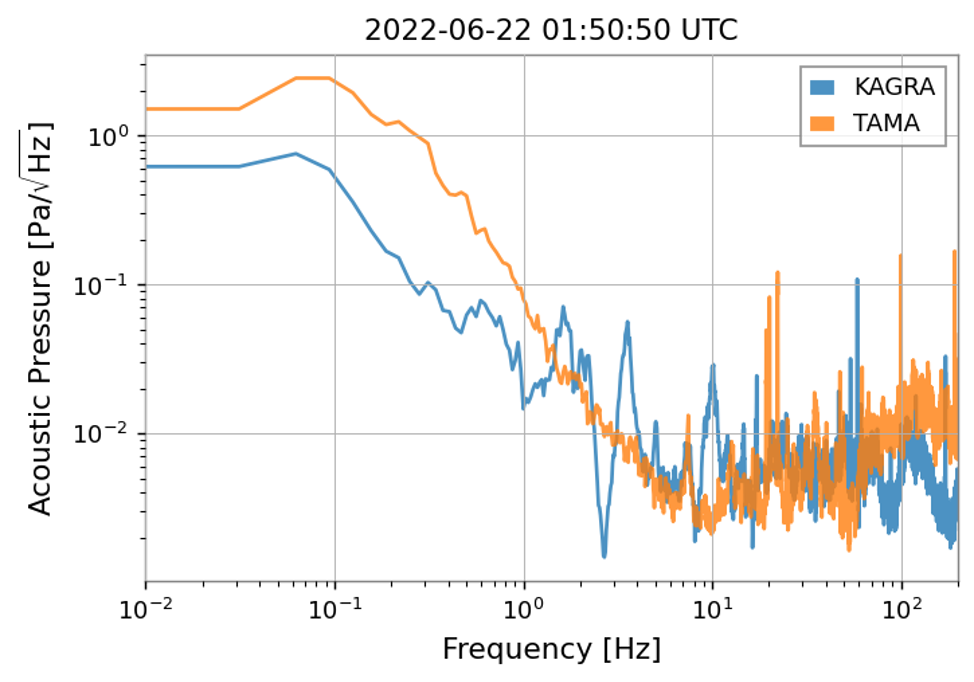
The attached plots are seismic and acoustic data.
The units are "count", not calibrated to um/s more Pa.


Seismic data of KAGRA is under OMC chamber and the microphone is in the IMC refl.
The large peak at one-handed several-tens Hz of the seismic data is the self-noise. (data sheet)
Below 1Hz, microseismic band, the ASD is large on Saturday night. It is consistent with the ocean wave.
At around 3Hz, the ASD is large on Saturday night and Monday morning, and small on Sunday.
Between 10 Hz and 20Hz, the ASD is large on Monday Morning.
Around 30 Hz, sometimes strange bumps are observed.
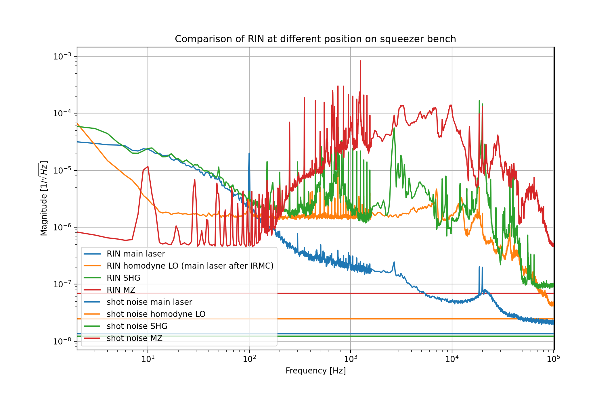
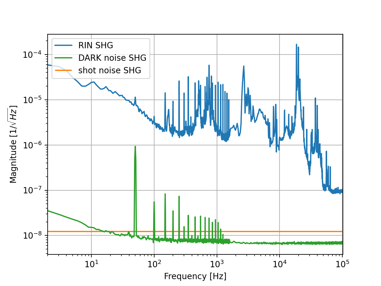
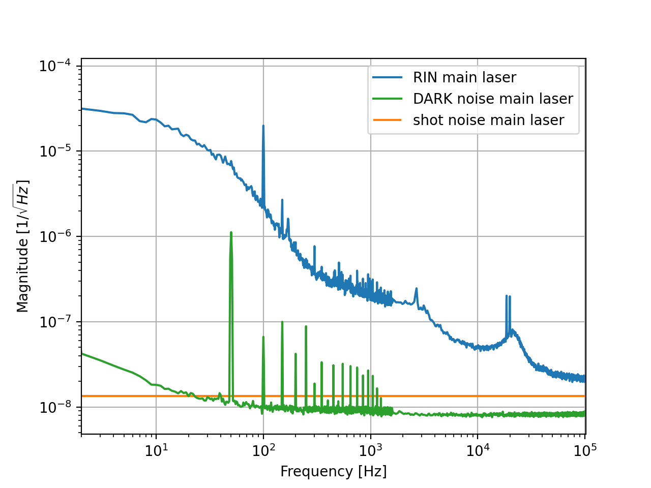
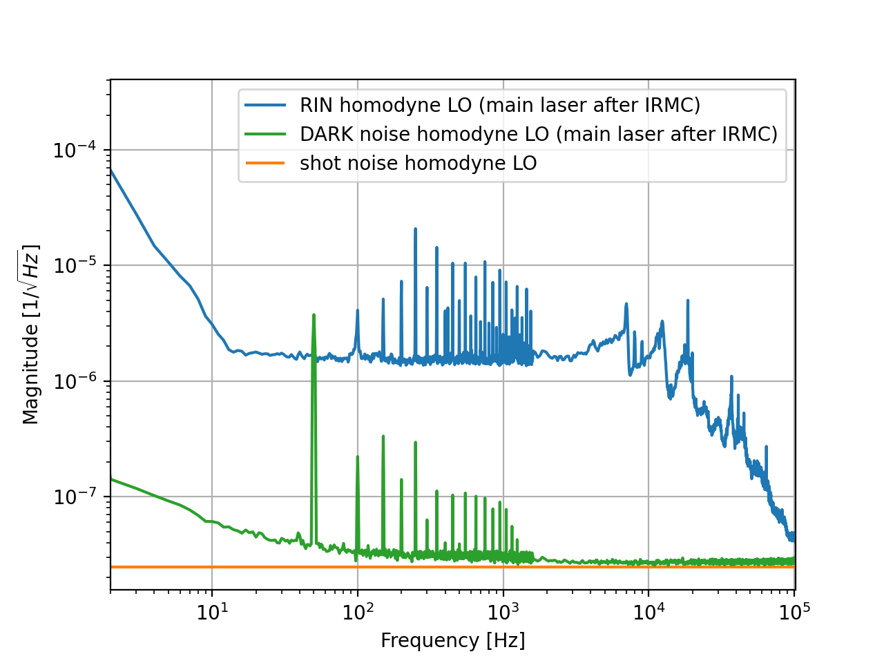
A comparison of RIN, shot noise and photo detector dark noise is shown in the attached first figure for several locations on the squeezer bench. Other figures show these noises for different single location separately.
[Takahashi, Aritomi, Yuhang]
Since BS suspension motion was too large and the pitch picomotor can move in only one direction, we opened BS chamber and checked suspension. Takahashi-san found that the magnet was touching the coil holder so he adjusted it.
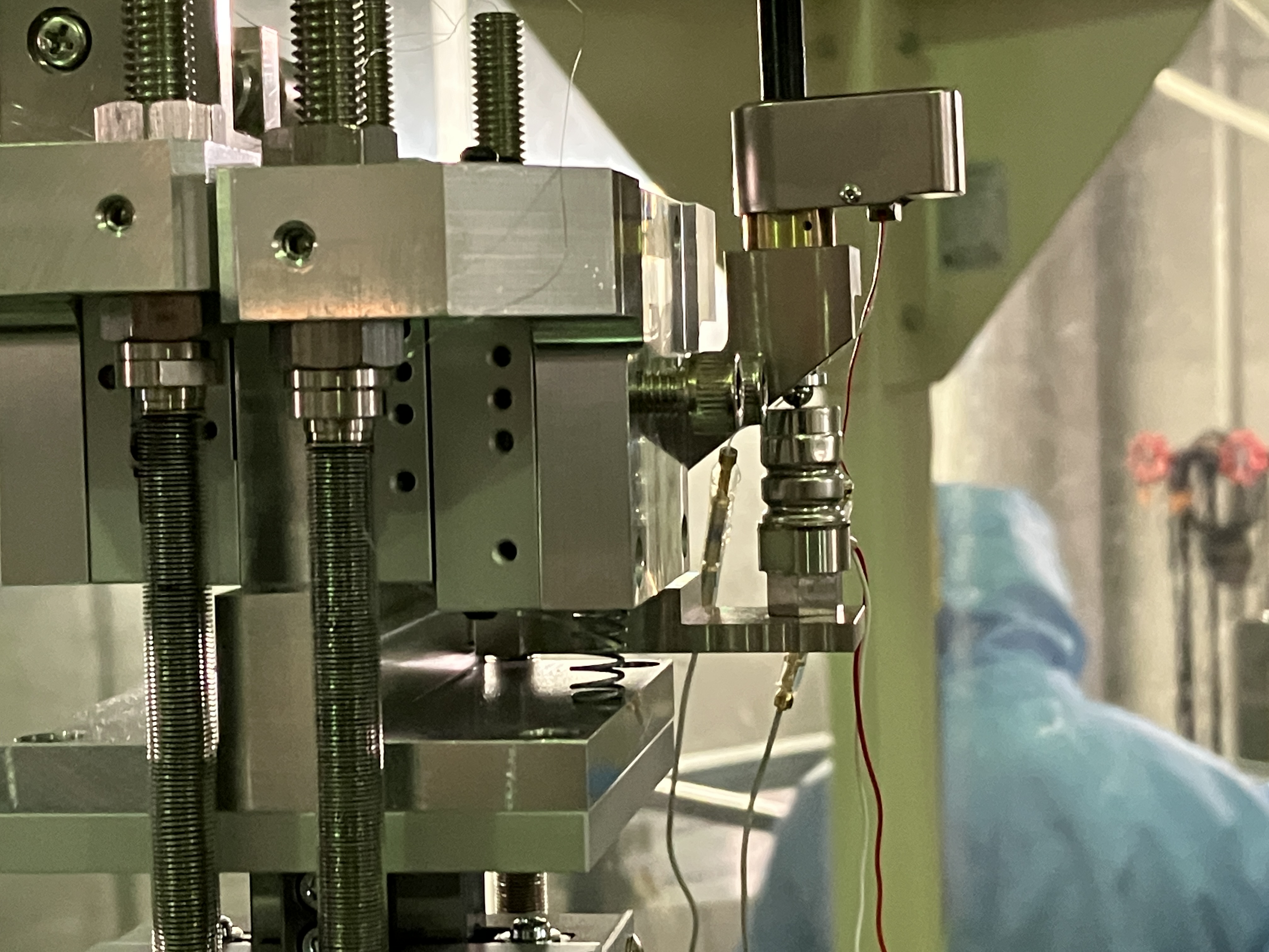
Regarding the picomotor, the picomotor cannot move in one direction because the required force to move the picomotor in the direction was too large. To reduce the required power to move the picomotor, Takahashi-san put a spring (Fig. 1). Then the picomotor can be moved in both directions.
We aligned PR and BS to make the green beam at center of the GV between input/BS and the first target.
Before closing the chamber, we checked BS oplev transfer functions (Fig. 2,3) and response of each coil. The transfer function and coil response are fine.
Finally we closed the chamber and started the evacuation of BS chamber.
Dan Chen, Marc
Today we assembled on the 75 * 90 cm optical table the frame of the dark box inside which we will perform the scattering measurement.
We also placed AZTEC #1 and #3 on holders inside the frames.
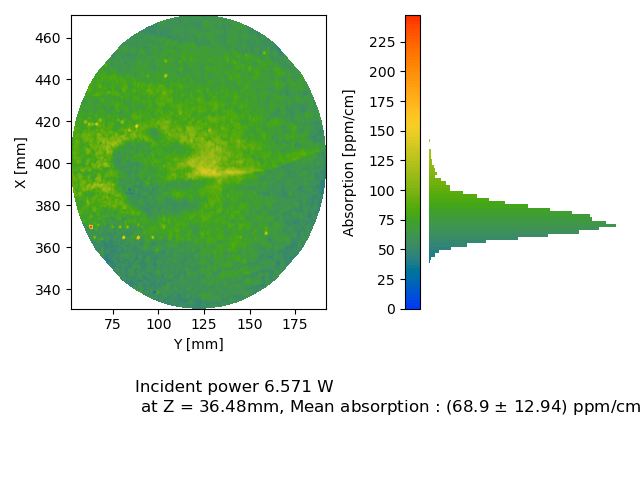
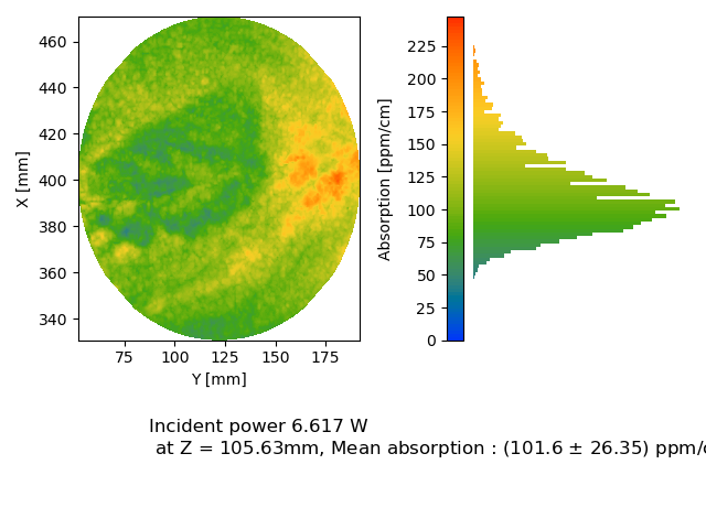
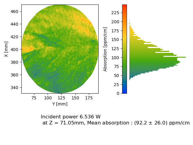
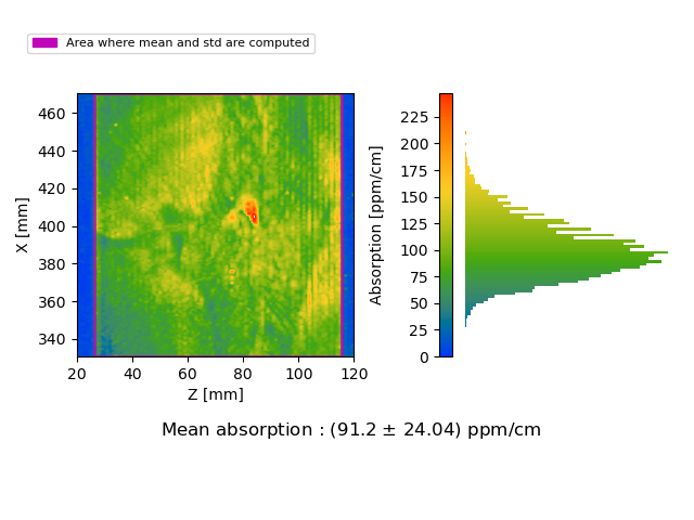
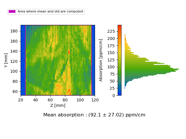
Report about AZTEC #4 absorption.
It seems to be around 100 ppm/cm and some fishbone patterns are visible as well.
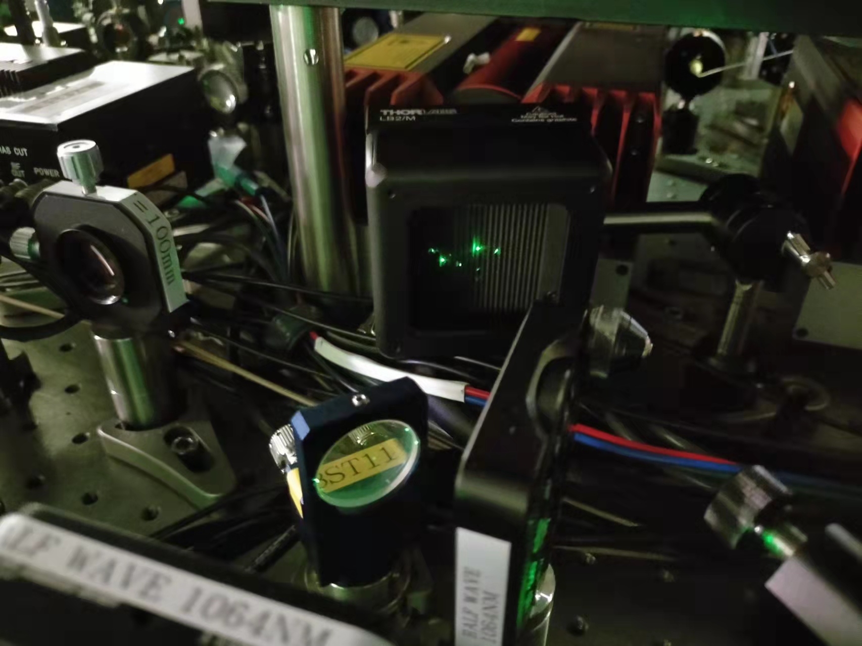
A proper beam dump thorlabs LB2 (1um - 12um) is installed for the newly replaced BS mount (as shown in Fig.1).
Although we can see some green light, let's remind that it is because the camera sensor is more sensitive to green as our eye. There are proper Dichroic mirrors to remove them.
Yuhang, Aritomi, Marc
A new PD (PDA36A-EC) is used (gain is chosen as 0dB), firstly DARK NOISE is measured (saved as DARKL.txt and DARKH.txt)
A LA1608-YAG lens (75mm) was always used when the beam is apparently large.
1. Measure Mephisto RIN. It is measured at the location where we pick off main laser for CC PLL LO.
The DC voltage is measured as 2.66, 2.61V and 2.67V (measured before and after spectra measurements). (saved as MAINL.txt and MAINH.txt)
2. Measure homodyne LO RIN. It is measured just after IRMC transmission.
The DC voltage is measured as 800mV, 780mV (measured before and after spectra measurements). (saved as LOL.txt and LOH.txt)
3. Measure SHG generated GR RIN. It is measured before MZ.
The DC voltage is measured as 3.14V, 3.16V, 3.24V (measured before and after spectra measurements). (saved as SHGL.txt and SHGH.txt)
This is an experiment record. An analysis of data will come later.
First we replaced the broken BS oplev PSD and measured BS oplev spectra as shown in the attached figure. The noise floor of BS oplev spectra is fine, but BS suspension moves a lot. In addition, BS pitch can go down with picomotor, but cannot go up. We need to open BS chamber again...
We somehow aligned FC and could see the green flash, but green beam spot at FC transmission moves too much due to BS suspension motion.
Then we found that we cannot maximize TEM00 very well and yaw misalignment cannot be removed.
We aligned green injection in yaw before as reported in elog2940. We doubt that this could cause some problems. So we tweaked the green injection, but the green flash still had yaw misalignment. After we brought the green injection back to the original alignment, END yaw was misaglined a lot and we had to move the END yaw with picomotor. We went to END room and moved END picomotor with a joystick. However, at some point, END yaw picomotor stopped moving and we lost green flash...
To do list for END mirror:
- center END oplev and check END oplev spectra/transfer function
- install a new picomotor driver to avoid going to END room for picomotor control
- If END oplev spectra are strange or picomotor does not move with the new picomotor driver, open END chamber and check the suspension and picomotor
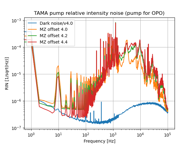
The OPO pump relative intensity noise was measured at different power level.
1. MZ offset 4.2 (25 mW), DC voltage on oscilloscope 320mV
2. MZ offset 4.4 (35 mW), DC voltage on oscilloscope 441mV
3. MZ offset 4.0 (15 mW), DC voltage on oscilloscope 186mV
As a reference, in LIGO, the SHG RIN is about 3e-6 from 3Hz to 400Hz. Then it gradually increases to 3e-5 at 4kHz. This indicates that the control servo has 1/f slope. (alog45088)
So we have a better RIN at low frequency (limited by PD dark noise). But a worse RIN at kHz region.
Yuhang, Aritomi, Marc
A new PD (PDA36A-EC) is used (gain is chosen as 0dB), firstly DARK NOISE is measured (saved as DARKL.txt and DARKH.txt)
A LA1608-YAG lens (75mm) was always used when the beam is apparently large.
1. Measure Mephisto RIN. It is measured at the location where we pick off main laser for CC PLL LO.
The DC voltage is measured as 2.66, 2.61V and 2.67V (measured before and after spectra measurements). (saved as MAINL.txt and MAINH.txt)
2. Measure homodyne LO RIN. It is measured just after IRMC transmission.
The DC voltage is measured as 800mV, 780mV (measured before and after spectra measurements). (saved as LOL.txt and LOH.txt)
3. Measure SHG generated GR RIN. It is measured before MZ.
The DC voltage is measured as 3.14V, 3.16V, 3.24V (measured before and after spectra measurements). (saved as SHGL.txt and SHGH.txt)
This is an experiment record. An analysis of data will come later.
A comparison of RIN, shot noise and photo detector dark noise is shown in the attached first figure for several locations on the squeezer bench. Other figures show these noises for different single location separately.
With help of Yuhang we removed #3 from the translation stage.
Then, I measured the bulk reference sample at the usual position and got R = 0.611 cm/W.
I installed the 1.5 inch sample and measured its absorption at the longitudinal center.
I measured about 35 ppm/cm which is compatible with old measurements.
Finally, again with Yuhang help, we installed the #4 and started absorption measurement.
Marc, Yuhang
Yesterday I tried to remove the 4 screws holding one of the 2 crystal.
Once they are removed, it is possible to access 2 set screws that fix the linear translation stage.
The 4 screws were really tight and I only manage to remove 3.
With Yuhang help, we tried to remove the fourth one without success.
In the end, we broke a screwdriver head inside the screw..
Fukushima-san from ATC helped us to remove it today.
After that the linear translation stage was replaced with a motorized one and the Soleil-Babinet is now closed with 3 out of 4 screws (need to purchase the broken one).
Yuhang and Michael
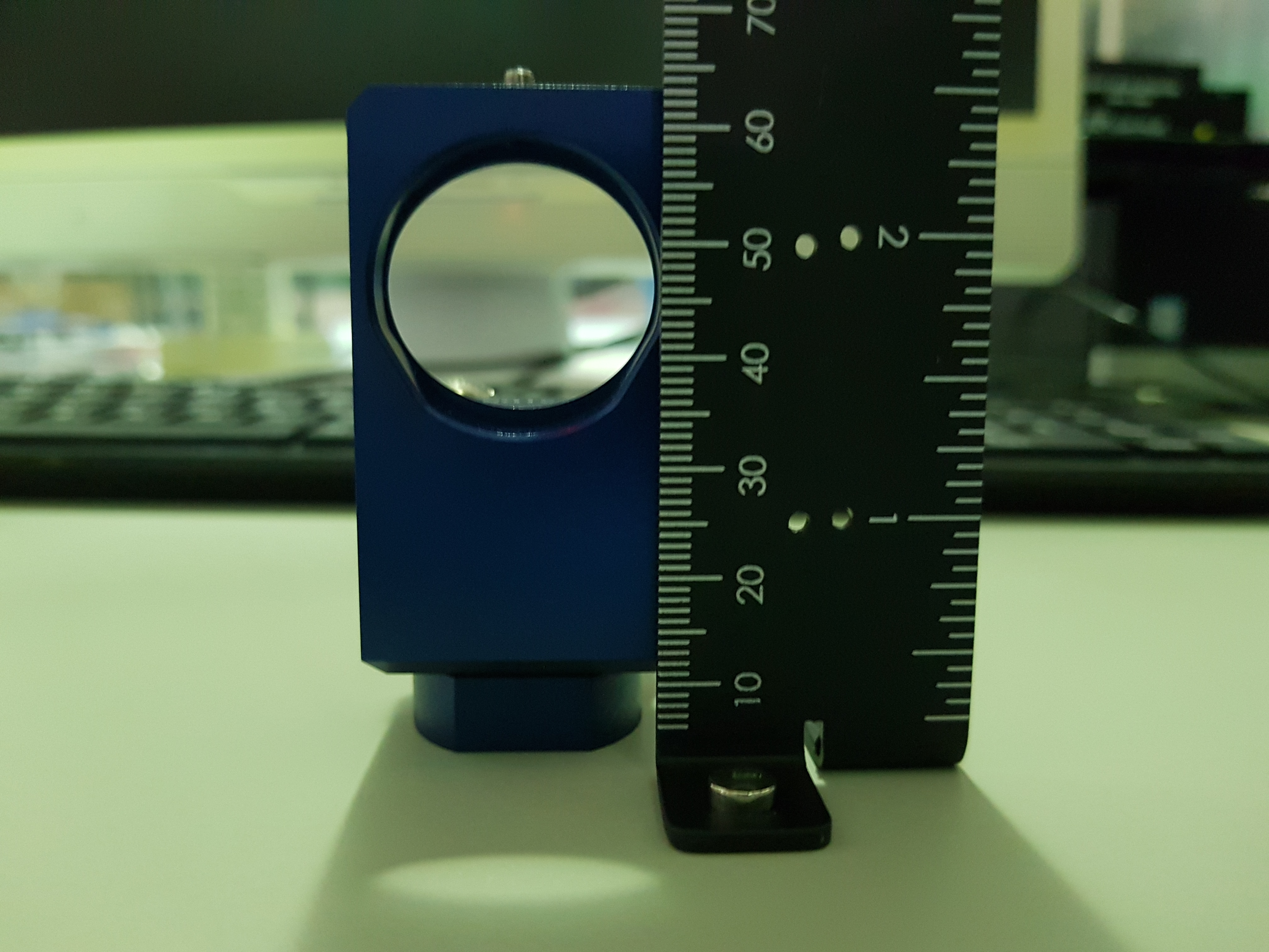
We replaced the mirror mount for the beam splitter that goes into the SHG. The new mirror mount is much smaller, allowing us to more easily remove ghost beams and scattered light from the squeezer bench.
The beam splitter was replaced by roughly using an iris, SHG opening and GRMC EOM as beam position references. First, the beam splitter was moved by hand to align to the references. Fine tuning allowed us to recover the SHG mode matching to slightly better than the previous alignment condition.
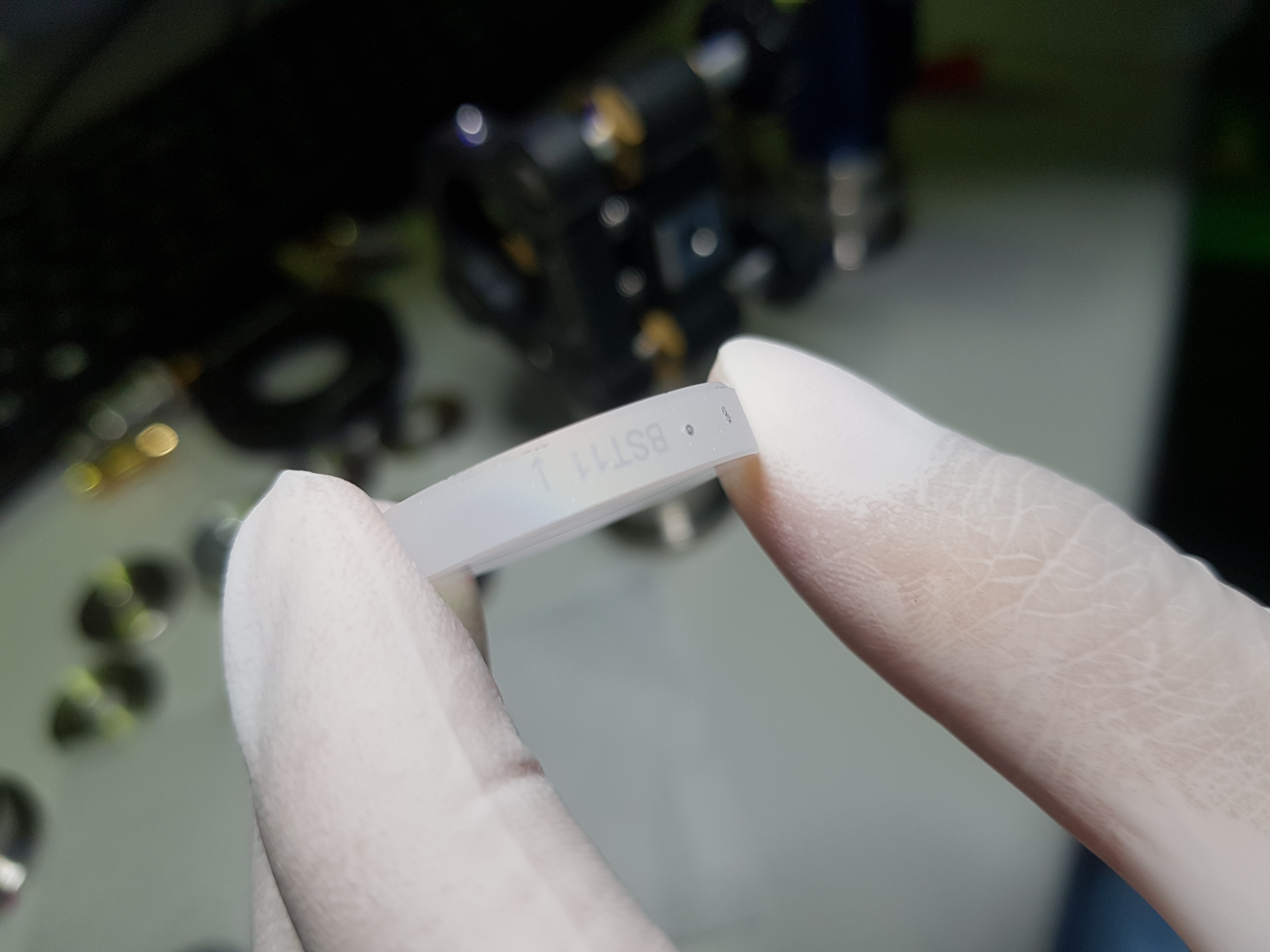
Reference SHG alignment is shown in figure 1 and 2. BS model number is in figure 3. The mirror mount type is shown in figure 4.
A proper beam dump thorlabs LB2 (1um - 12um) is installed for the newly replaced BS mount (as shown in Fig.1).
Although we can see some green light, let's remind that it is because the camera sensor is more sensitive to green as our eye. There are proper Dichroic mirrors to remove them.
Marc, Yuhang
Today the AZTEC #4 was delivered.
We brought it to the PCI cleanroom and applied first contact on one surface.