NAOJ GW Elog Logbook 3.2

Yesterday we have worked on the characterization of the filter cavity lock.
First we have experienced some trouble with the labview ADC of the local control signals for the input mirros. The error signals for the pitch and the yaw looked the same. After some attempts the problem was solved simply by switching off and on the CPU unit. We have already observed this problem in the past but I could not understand what triggers this kind of behaviour.
After recovering the local control we could align and lock the cavity.
At first we wanted to measure the calibration factor for the error signal. In order to do that we summed a line to the piezo correction (input channel " RAMP") above the UGF.
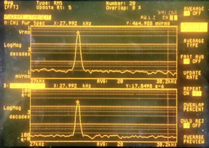
We monitored the amplitude of the line on the monitor channel "PZT mon" finding a value of V_RMS = 17.84e-6 V.
The correspondent amplitude in Hz is
S_Hz = V_RMS (V) * 100 * sqrt(2) * 2e6 Hz/V = 5045 Hz (1)
The factor 100 is the attenuation of the "PZT mon" channel
The factor sqrt(2) is to pass from V_rms to the line amplitude
The factor 2e6 Hz/V is the gain of the piezo after the SHG
The correspondent amplitude observed in the error signal is
Err_V = K(V/Hz) * S_Hz/sqrt(1+ (f/f_0)^2) = sqrt(2)* 0.465 V (2)
% (2020/09/04) Note that this formula should be Err_V = K(V/Hz) * S_Hz/sqrt(1+ (f/f_0)^2)
Where we have taken into account the effect of the cavity pole assumed to be at f_0 = 1.45 kHz.
Comparing the amplitude of the two lines (see picture 1), inverting Eq. 2. We could find the calibration factor K (V/Hz) = 2.5 e-3
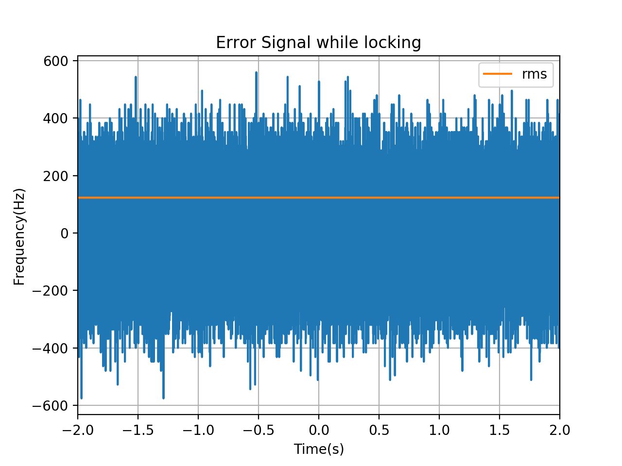
We have used it to calibrate the error signal into Hz and we obtain a lock accuracy of about 120 Hz, (see picure 2) which is similar to what we obtained in July.
We have also performed a noise injection to measure the open loop TF finding a UGF at about 10 kHz with a phase margin of 50 deg. (See picture 3)
We have tried to change the gain but we observed that it was already optimized to have the error signal as small as possible.
In picure 4 the transmission of the filter cavity is plotted.