NAOJ GW Elog Logbook 3.2

[Aritomi, Yuhang]
First we maximized IR reflection from filter cavity while we couldn't find IR resonance at that point. The reflection was 84% of injection.
Then we aligned LO and BAB reflected by unlocked filter cavity into AMC and measured visibility.
Calculated visibility is somehow more than 100% but it should be good anyway. Good news is that visibility is stable although we have jittering.
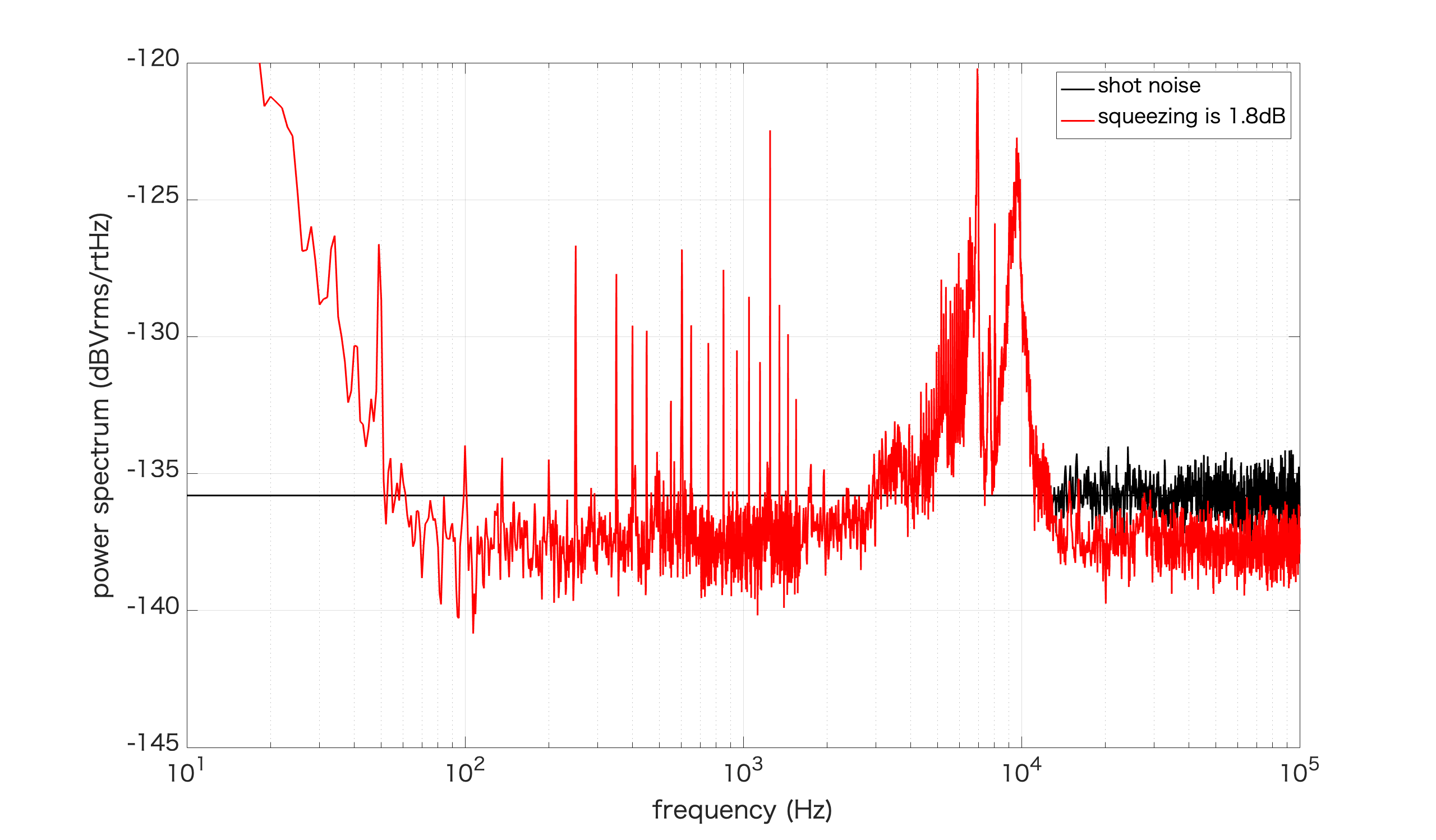
Finally we measured squeezing spectrum when squeezed light is reflected by unlocked filter cavity (attached picture). Injected green is 40mW and demodulation phase for squeezing is 190deg. We have 1.8dB squeezing down to 60Hz. Since it seems we have much larger phase noise from filter cavity (It will be reported later), we may have more squeezing when pump green is lower. Large bump below 60Hz is unknown. Noise around 10kHz should be phase noise of laser since we turned it on today.
Current problems:
1. Large bump below 60Hz
2. Large phase noise from filter cavity and CC2 control is not so stable
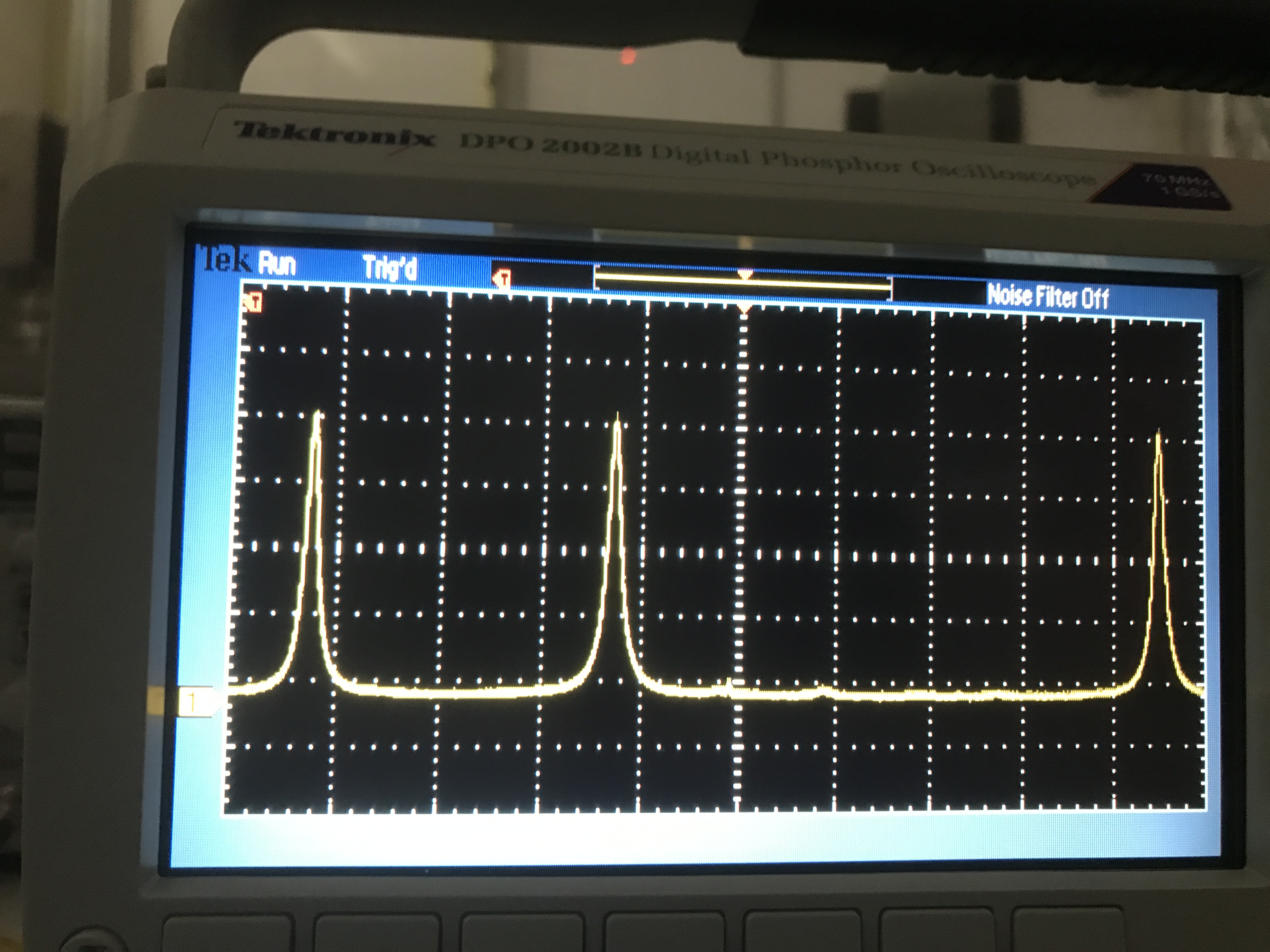
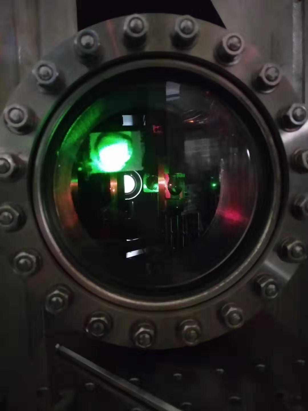
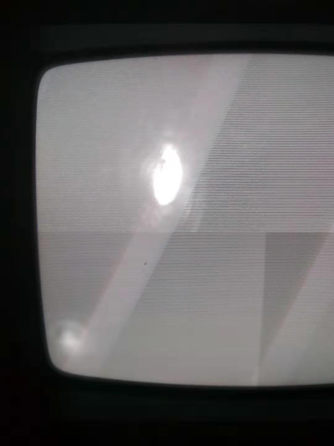
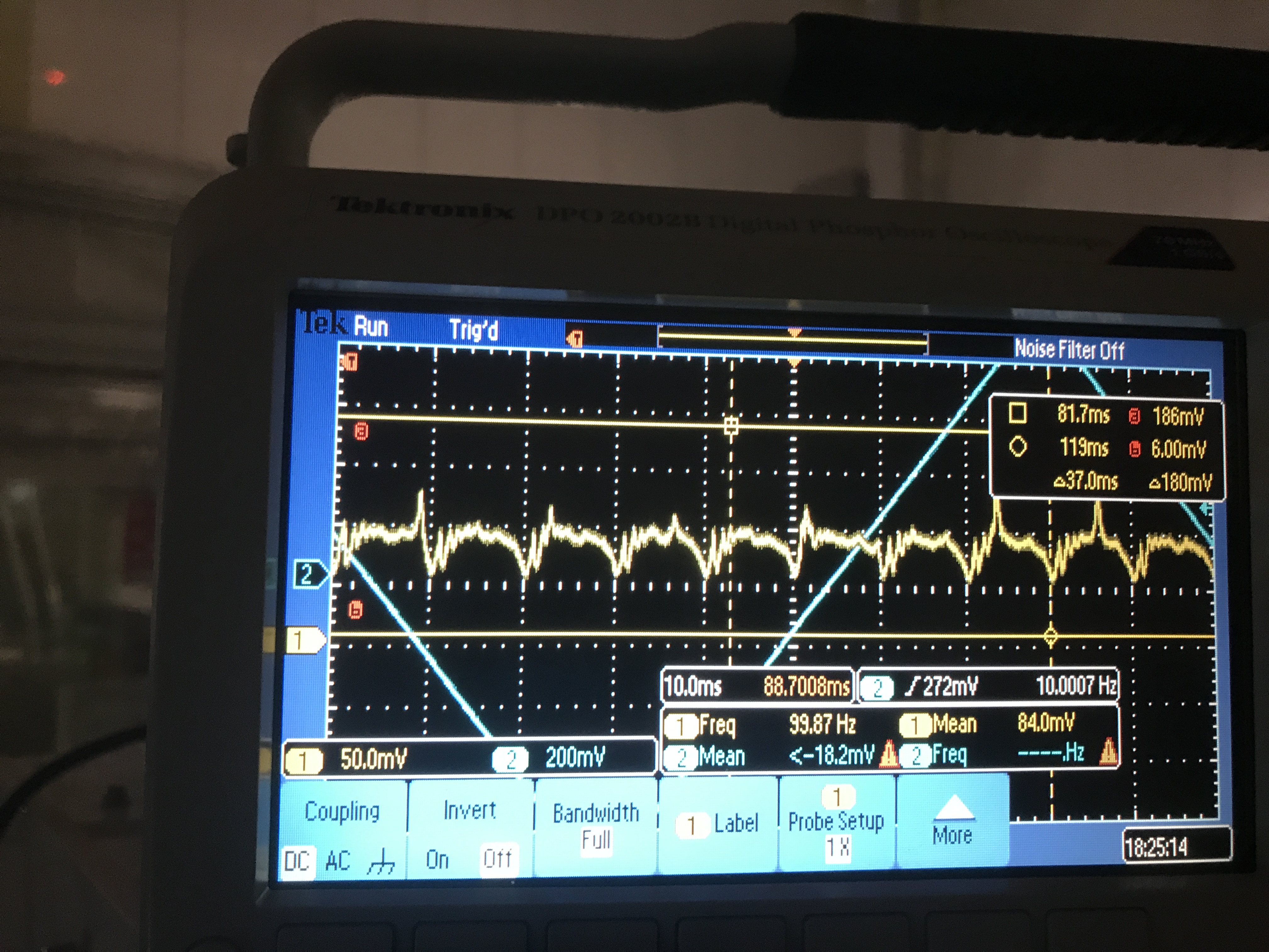
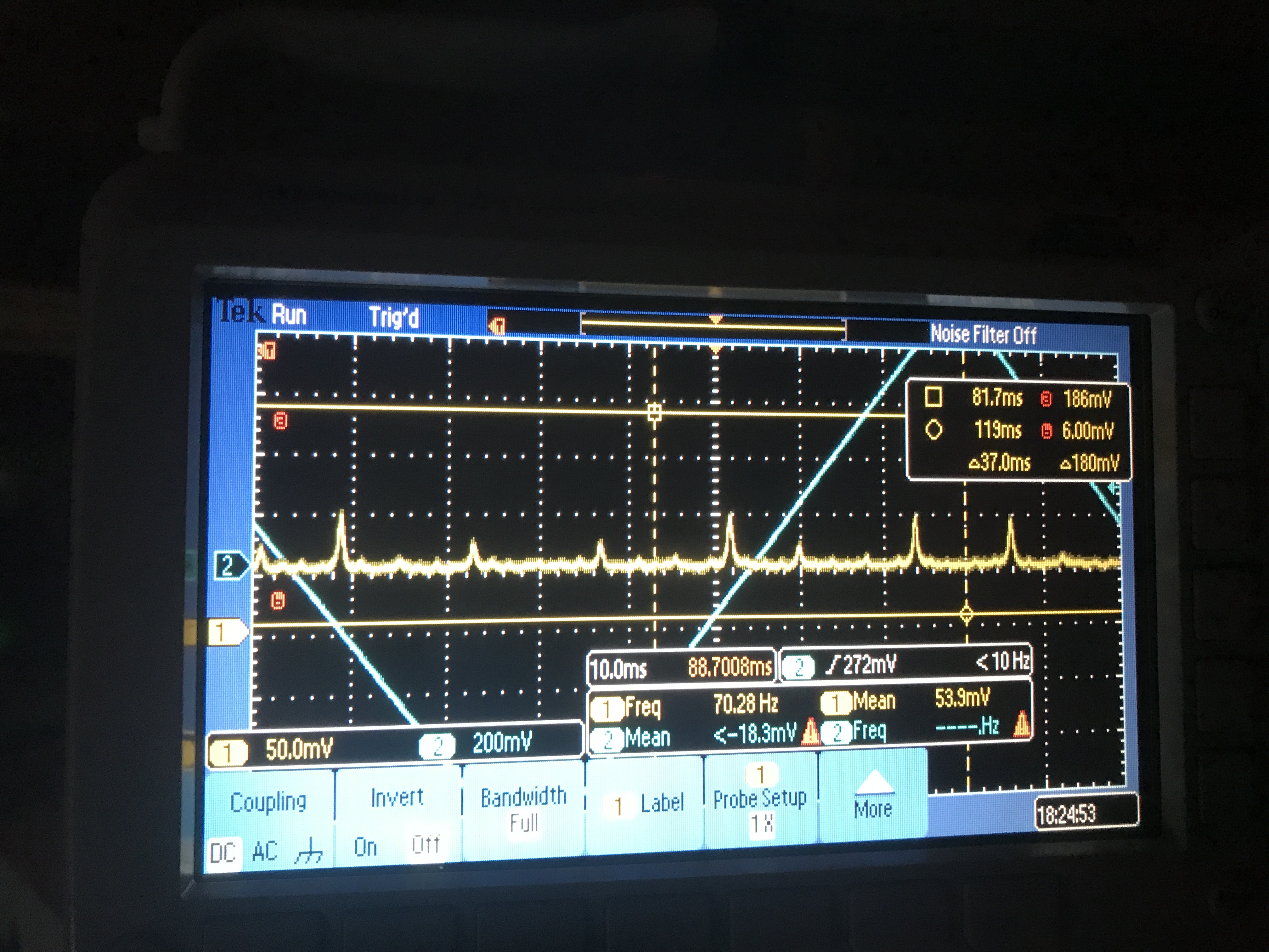
I aligned reflection from filter cavity to AMC to see jittering effect while IR injection is still not aligned. Attached picture shows BAB mode matching in AMC when alignment is good. Largest peak is TEM00 and small peak next to TEM00 is pitch misalignment. We can see pitch jittering effect from attached movie.

[Aritomi, Yuhang, Yuefan (remotely)]
Yesterday we found IR reflection from filter cavity was only 33% of injection and IR on PR reference was 15% of injection. The reason was that polarization after faraday on the bench we recently installed was not s-polarization due to faraday rotator and some of BAB were lost in PBS before and after faraday in PR chamber. So we put HWP just after faraday on the bench and optimized the polarization. As a result, reflection from filter cavity becomes 85%.
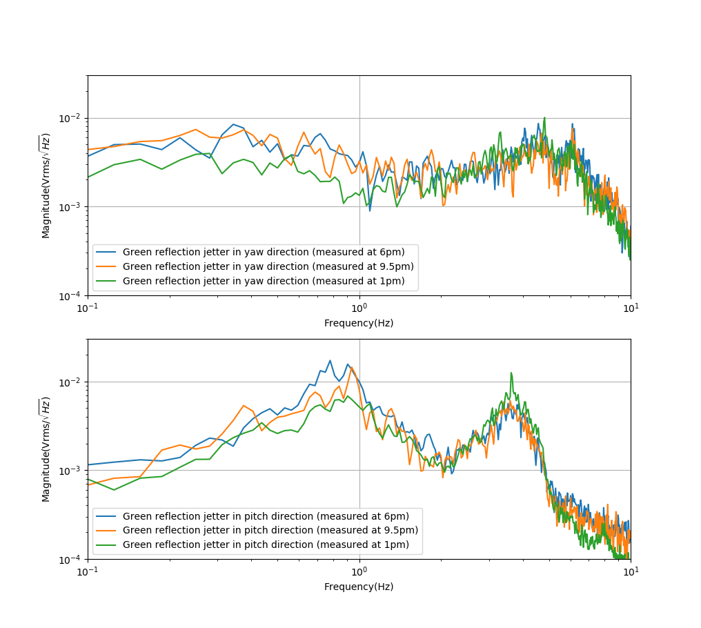
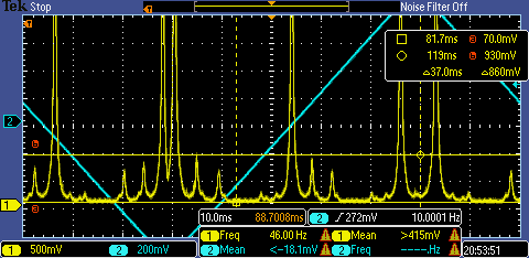
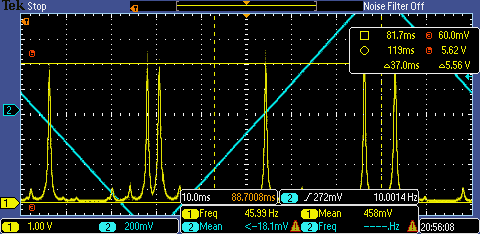
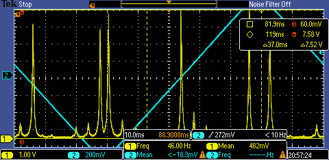
Here is the measuremrnt of green reflection jittering at 1pm, 6pm and 9pm.
It seems that they are similar.
Aritomi and Yuhang
Today we realigned again the GR.
GR on the PR chamber target was fine. (See attached figure 1)
GR on the BS target was moved in the pitch direction. If I remember well, Eleonora intentionally removes the DC offset of PR local control. And after about two weeks, the pitch was misaligned. Maybe this means PR mirror has pitch drift without local control. (See attached figure 2)
Then we moved picomotor of PR to recover GR on the BS target.
We moved picomotor of BS to make beam go through the first iris. We also moved picomotor of BS again and made beam go through the second iris. After that, we found the transmission was not hitting the center of the camera. Since we think two irises along the filter cavity should be the best reference, we decided to move the camera to center beam on the camera. But we didn't move the fork of camera, so if this should not be done we can also recover easily. The situation before we moved camera was attached figure 3.
Aritomi and Yuhang
We found that the incident beam into the filter cavity actually it is not jittering.
But we confirm that ITM and ETM are jitter. For ITM, it is obvious that reflection is jittering. For ETM, we found ETM reflection and it was moving.
Please check the attached video. This is the green incident beam on the second target. https://drive.google.com/open?id=1O6HZabKGtyzbuyYSPC_QGHkkhuE3W1YI
Simon, Matteo
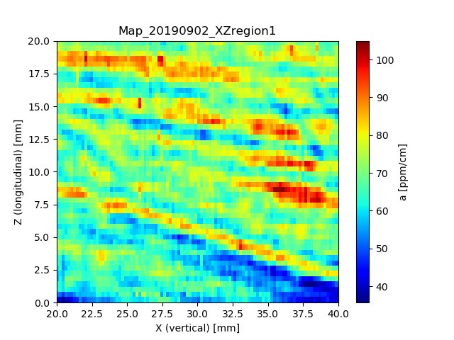
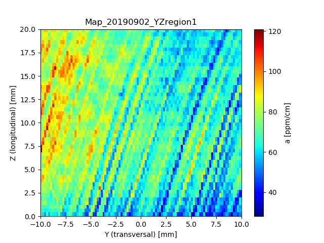
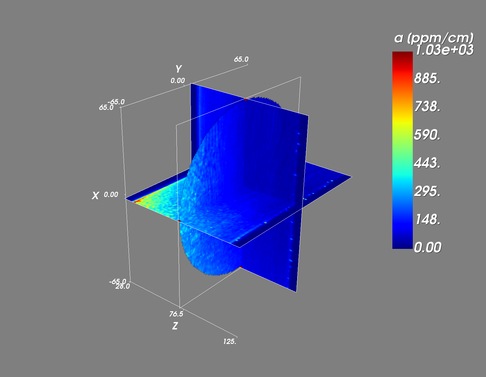
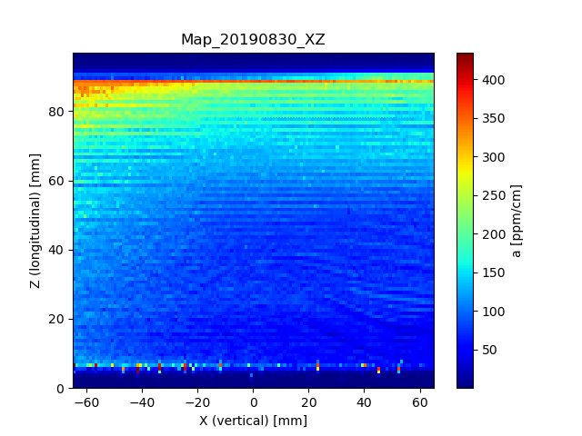
We decided to focus on some more preciser maps on spare ETMY, especially in YZ, since in the full map XZ we could see some layer-like stuctures but not in the full YZ map, which should be the case. This is probably due to a lower contrast as in YZ we have a much larger range in the absorption coefficent.
The results of the measurements can be shown in the attached figures. We can indeed see now those layer-structures in both XZ and YZ planes, as we expected.
About the reason of these layers, we can only speculate but it seems that they have their origin in some systematic oscillations of impurity concentrations during the crystallization process.
In addition to that, I finished writing the 3D representation part of the absorption maps in Python by using Myavi. I attached also a picture of the results from the last full-map measurements.
Aritomi and Yuhang
After the simulation, we implemented the filter cavity reflection telescope. It was quite strange that I moved a lot to match this beam into AMC. Maybe this is because of the injection is not well mode matched, so the reflection is also not in good shape. But anyway, we put this telescope and tried a lot to improve the matching.
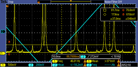
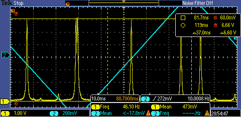
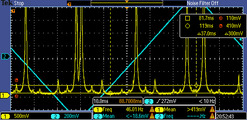
The preliminary result is as the attached figures.
In the first attached figure, we could see there is a mode mismatch peak with a height of 540mV.
In the second attached figure, we could see there is a TEM00 with a height of 6.6V.
In the third and fourth figure, you can find a peak just beside the mode-mismatch peak. It changes height because of the beam jittering in pitch direction. And it can have height up to 860mV.
In the fifth and sixth figure, you can see the TEM00 peak can also change from 5.5V to 7.5V.
Conclusion:
1. We have roughly mode mistach now for filter cavity into AMC as ~7.5%.
2. Beam jittering brings misalignment of up to ~12%.
3. The estimation is not precise because the total reflected IR power also fluctuates. From the experience of green reflection, we see much more stable green reflection after using smaller focal length lens. Maybe we are having this beam clipping issue also for this measurement in IR reflection. We should check this tomorrow.
Found on 5th September, the beam was clipped!
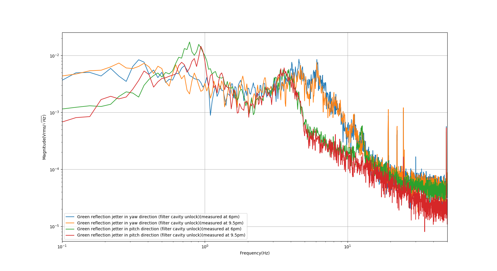
As we talked in the meeting, I did the measurement of beam reflection jitter by using QPD.
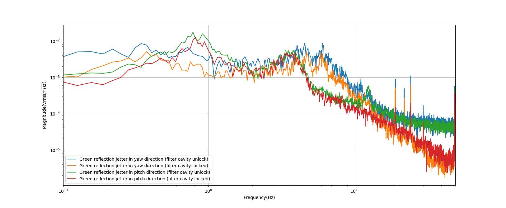
I did measurement first time just after the meeting, I measured the GR reflection beam jitter by QPD at yaw and pitch direction. I tried my best to center this beam and made the measurement. I also measured the beam jitter difference when the filter cavity is locked and unlocked. The result is attached in figure 1.
I did measurement again before leaving. This time I just measured when the filter cavity is unlocked. The comparison is in attached figure 2.
conclusion:
1. The lock of the filter cavity can reduce this beam jettering above ~10Hz. We know the correction signal we are sending to Main laser PZT is limited by laser noise above 10Hz. So I guess the lock of the filter cavity reduces the power coupling from higher-order modes to TEM00. And at low frequency, this is limited by the suspension. So if we engage the filter cavity length control, we may solve a bit this beam jittering problem. We should try to see this effect.
2. From the first plot, It seems pitch and yaw have different peaks. Yaw is worse at a higher frequency while the pitch is worse at a lower frequency.
3. From the second plot, it seems there is no obvious difference between 6 pm and 9.5 pm of beam jittering. I will check the situation in the morning and just after lunch.
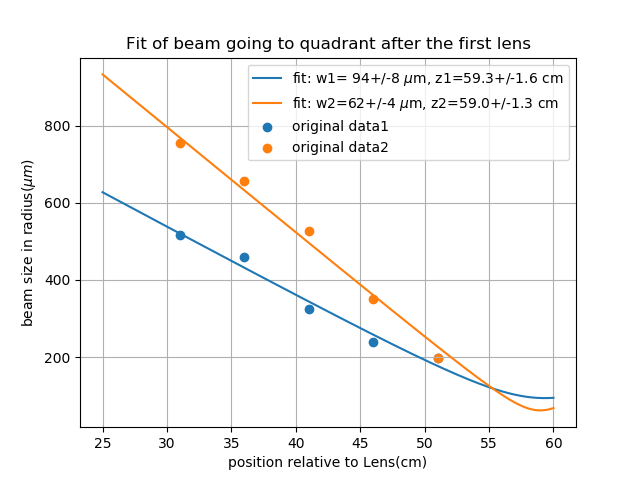
Aritomi and Yuhang
To make sure everything is going well, we decided to perform this measurement. From the simulation, beam waist should be 53.5cm after the lens and has size 146um.
From the measurement, the beam waist is 59cm after the lens and has a size around 80um. This is out of our exception.
Shall we adjust the telescope according to this measurement?
This is the light around the wall.
Here is difference when fluorescent light in TAMA is ON and OFF. Please turn it off when you want to measure small signal.
This is the light around the wall.
[Aritomi, Yuhang]
We could see BAB transmission (injection is 150uW) by CCD camera without amplification when IR is aligned and AOM frequency is optimized (Pic.1). We could also see BAB transmission with 11.5uW injection (Pic.2), so we can see CC transmission with current CCD camera.
[Aritomi, Yuhang]
| Mode | AOM frequency (MHz) | IR transmission |
| TEM00 | 109.03714 | 220 |
| HG30 | 109.22741 | 105 |
| HG10 | 109.42253 | 142 |
| HG40 | 109.62523 | 104 |
| HG20 | 109.8303 | 116 |
| offset | 92 |
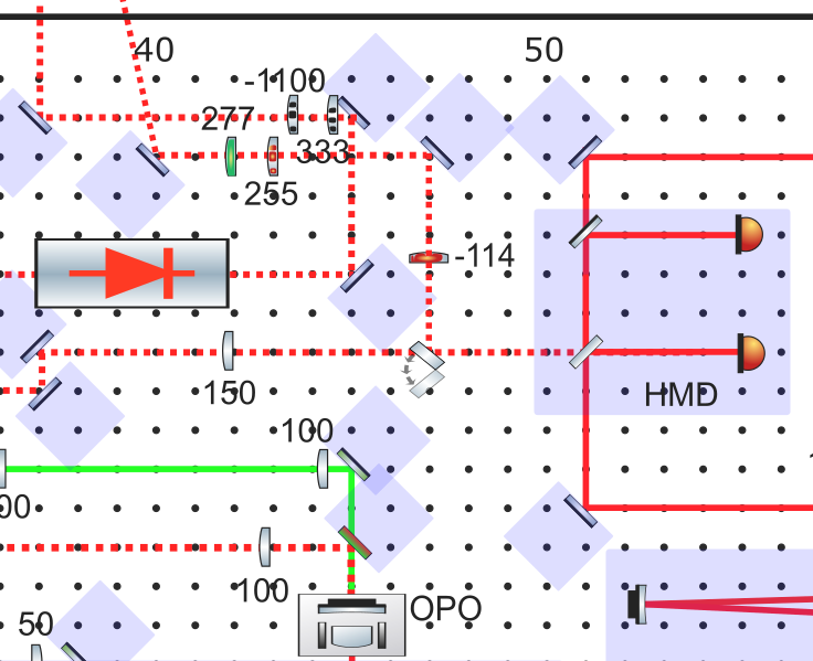
Here I put the position of lenses on bench for SQZ telescope. (comment to entry 1546)
For injection telescope, since we have no space to move now. So the solution is to buy RC4 from thorlabs. This new dovetail rail carrier will allow a movement of up to 3mm for 333lens and 10mm for -1100lens. And from the simulation, this is already enough range to improve mode matching. (this telescope is shown in black color in the attached figure 1)
Note: it seems lens333 is touching mirror, but it is not due to the small mirror mount we are using.
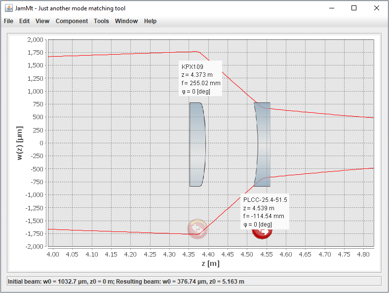
For reflection telescope, since we have only one superpolished lens. If we want to go on soon. We can temporily use KPX109 instead of CVI lens. From the simulation, these two telescope will be almost the same and PLCC51.5 will be at the same position. So it will also be easy to replace with superpolished lens in the future. (the red color lens is for the current implementation, lens in green color is the superpolished and will be implemented in the future)
The simulation of reflection telescope with newport lens is also attached as figure 2.
[Aritomi, Yuhang]
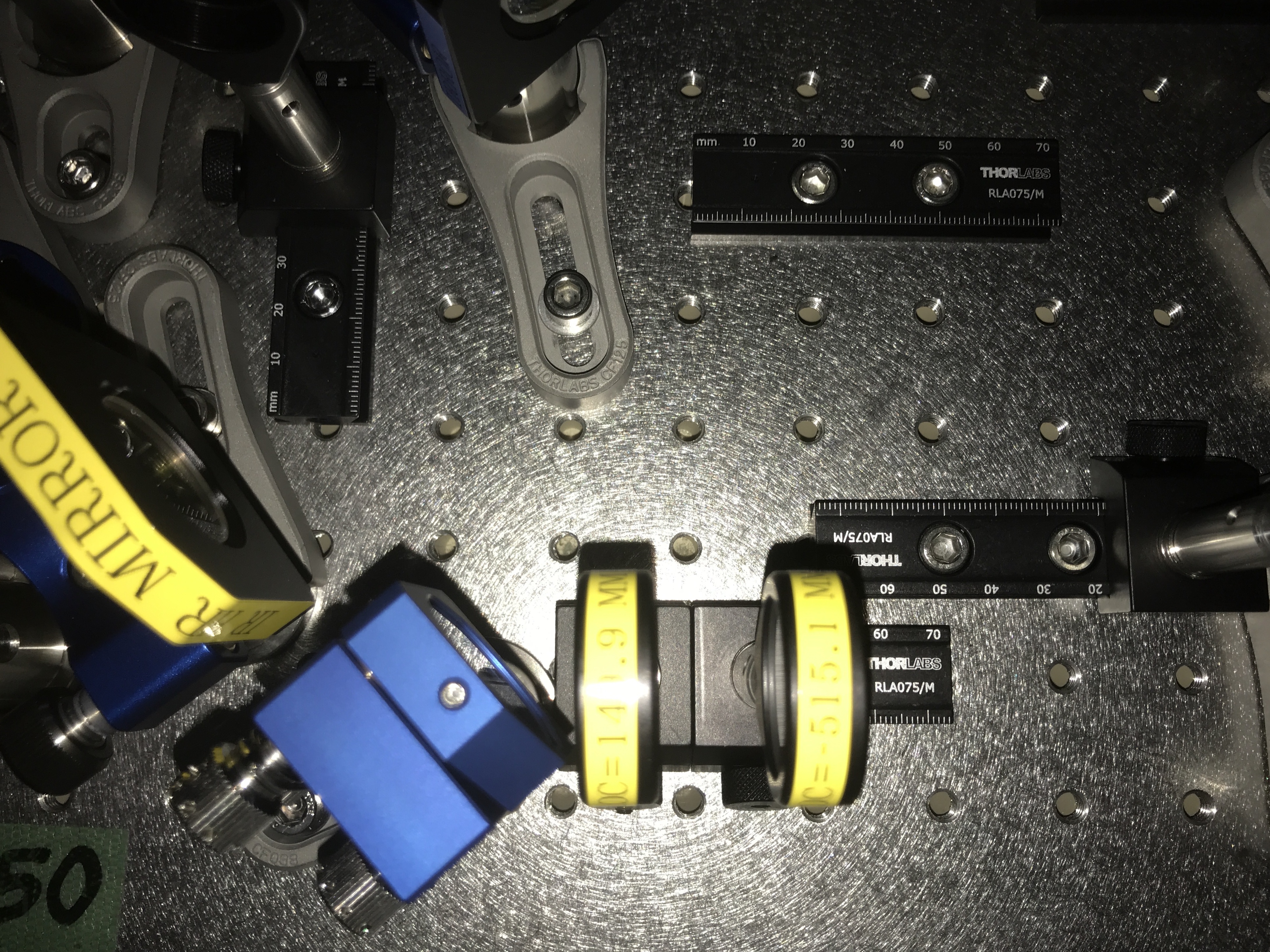
According to Yuhang's simulation (latest simulation is a bit different from this), we installed superpolished lens (PLCX-25.4-149.9-UV, PLCC-25.4-515.1-UV) for injection telescope. Unfortunately the two lenses are very close with each other (Pic. 1) and cannot be moved. We'll continue this setup for the moment and if mode matching is problem, we'll think another configuration.
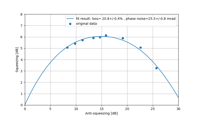
To extract loss and phase noise information and estimate error, the fit version of entry 1571 is attached here.
Aritomi and Yuhang
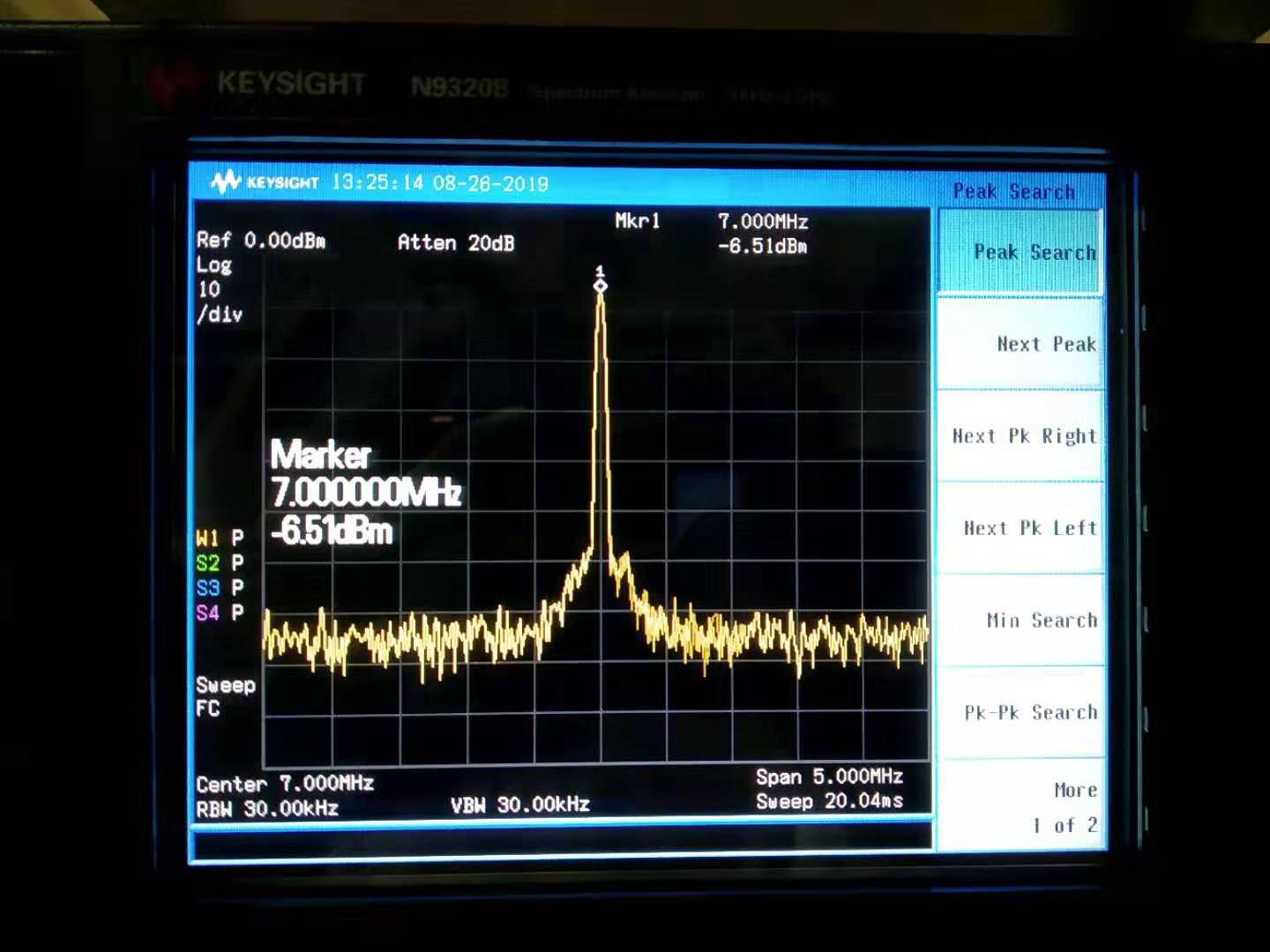
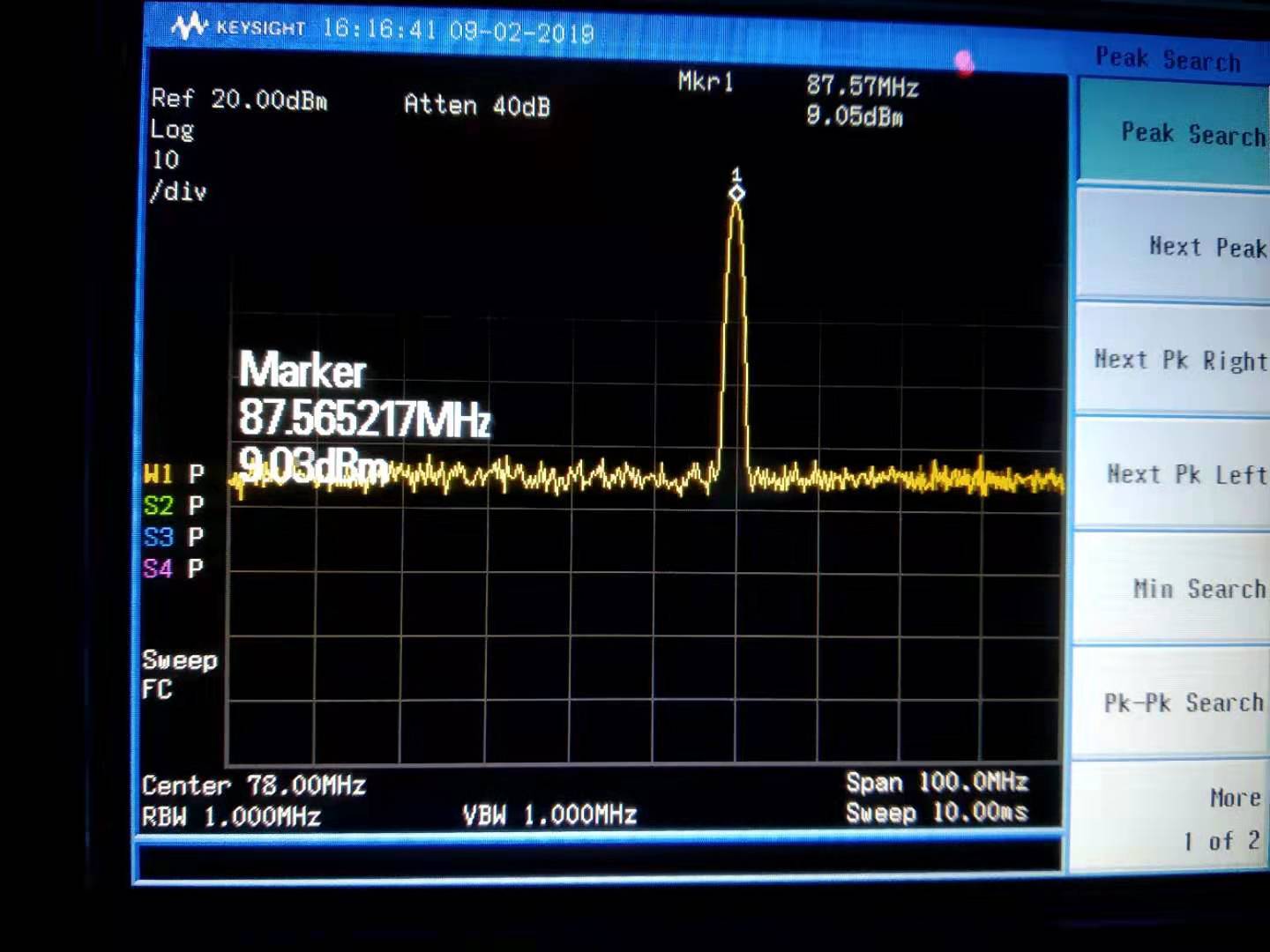
The output of DDS board is -6.5dBm(shown in the attached figure 1). While the AA demodulation board requires 4-15dBm signal. And this signal should come from the same DDS board with the modulation we send to the EOM (this is board 2).
So our strategy is:
1. amplify this signal by using RF amplifier ZHL-2 (it should have a gain of 16dB from specification)
2. use a RF splitter Z99SC-62-S+ (0-500MHz) to seperate this signal (the signal will degrade by 3dBm by splitting and loss 0.5dB because of losses)
3. in the end, from calculation, we should have identical signal 6dBm. And this is meeting our requirement.
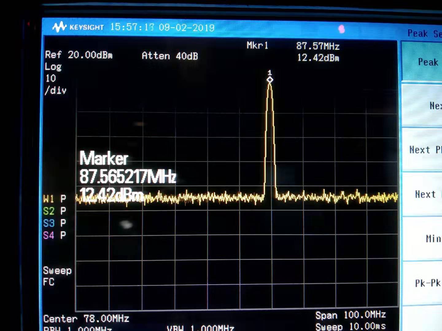
Then we measured the signal. The signal after RF amplifier is 12.4dBm(shown in attached figure 2), this means the gain is 19dB.
The signal after RF splitter is 9dBm(shwon in the attached figure 3).
So we can keep this configuratiuon for AA system.
Simon
Attached to this report is the result of mapping the absoprtion of spare ETMY in XZ directions. The map is oriented with the side facing the IU on top and the side facing the optical table on the left, so don't get confused!
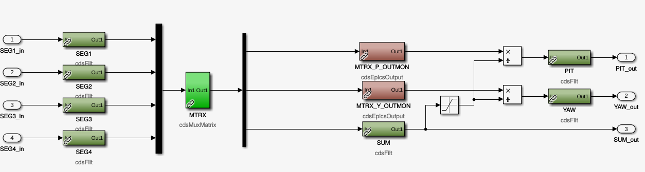
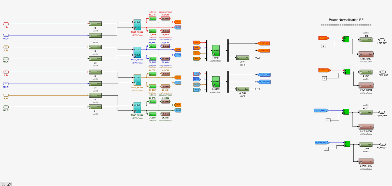
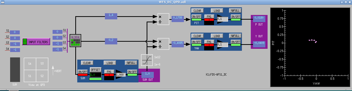
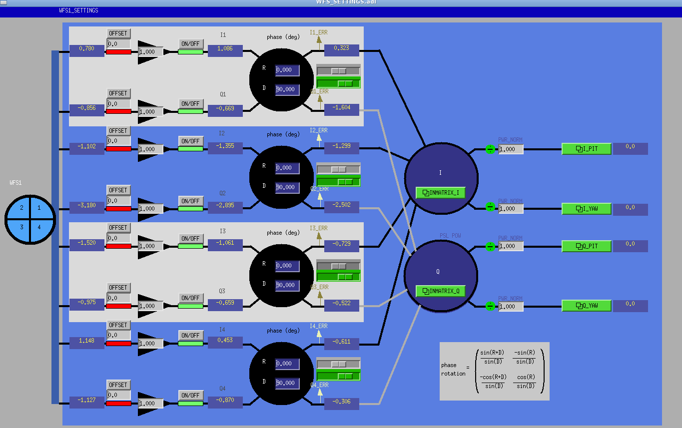
I implemented the real time and MEDM models for reading signals from WFS and convert it into pitch and yaw (including options for filtering, normalization, etc..).
The code is basically copied from KAGRA one. I implemented two subsystem models: one for DC signals (pic1) and one for RF (pic2). The corresponding medm screen are shown in pic3 and pic4.
I used two common medm screens model and passed it different variables, corresponding to the two WFS we plan to used (WFS1, WFS2). Everything seems to work fine.
At some point I mistakenly took a snapshot of the epic channels values just after restarting the model, so that the default snapshot file was overwritten with the initialized values. I contacted Miyakawa-san that explained me that every time the model is restarted a snapshot is automatically stored in the folder /opt/rtcds/k1/kagra/target/k1fds/k1fdsepics/burt wih. So I could restore the previous epic channel values by using this last snapshot file.
The next step will be to implement the sensing matrix and the feedback loop to the mirrors.