NAOJ GW Elog Logbook 3.2

I started the evacuation of input chamber. First I used rotary pump until the pressure in the input chamber reaches below 0.1mbar. After I removed the rotary pump, I closed the small gate valve close to arm and opened the small gate valve close to the input chamber. I will wait until the pressure in the input chamber reaches the similar one in the BS chamber.
Yuhang and Michael
We found an issue with the Mokulab unit used in the ATC cleanroom
We used 100 Hz 10 dBm 1Vpp signal from another function generator. Putting the signal into Mokulab IN2 and using the oscilloscope function shows no frequency signal and 4 mV offset. IN1 reads 9Vpp (+5.4, -3.6) at 118 MHz even with no connection.
Using 1 MHz signal into the spectrum analyzer function likewise shows no signal, just -131 dBm floor. Using a T connector from the function generator to oscilloscope and Mokulab, we see that the signal on the oscilloscope is reduced when switching from Moku IN2 to IN1, but no change when switching IN1 input impedance between 50 Ohm and 1 MOhm.
Mokulab function generator output works fine though, we have been using it to scan the cavity.
I have now taken 3 measurements with s polarization at the input that saturated the lockin amplifier..
It seems that we can really easily saturates the p polarization.
Indeed, it is connected to the old lockin amplifier where the range (0 to 1 V) is changed depending on the sensitivity setting we are using.
Now I'm injecting about 160 uW of power but when doing the measurement with s polarization it seems that the p polarization power changes by more than a factor 14...
I'm starting hopefully the last measurement with s polarization at the input where the sensitivity of the old lockin is set to 100 mV despite the value at the center being 0.2 mV.
It would be convenient to have a new lockin amplifier to avoid this issue...
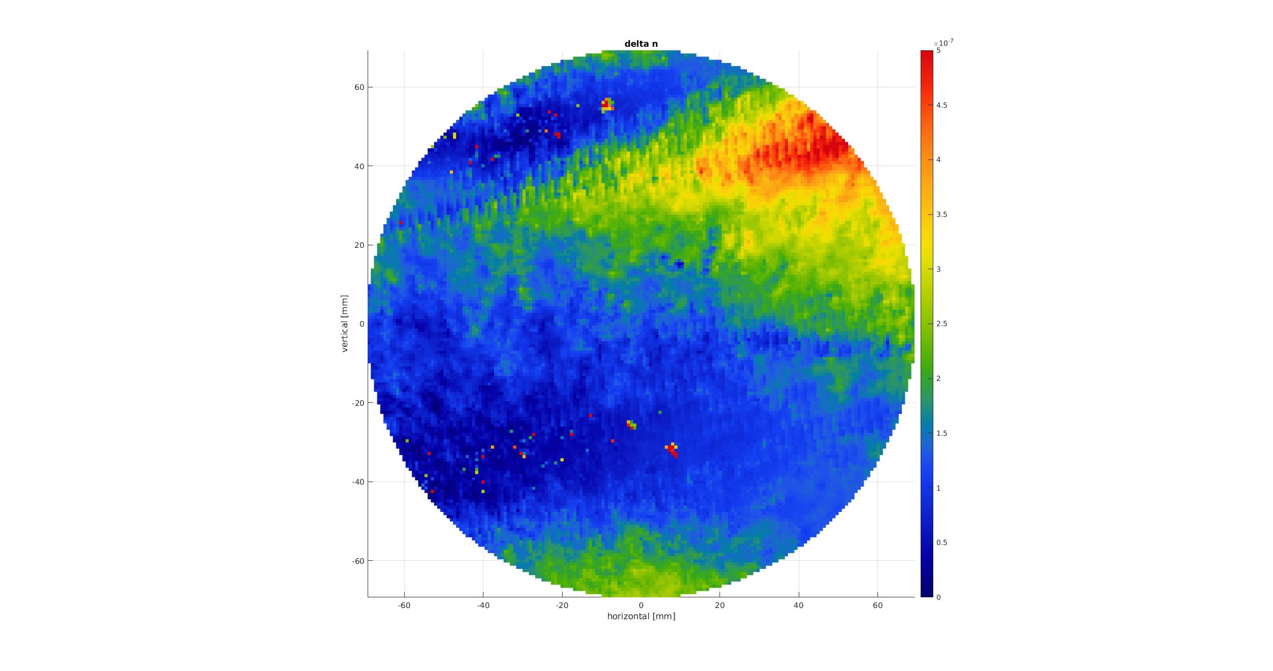
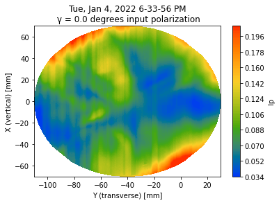
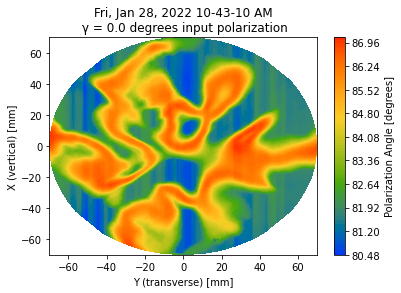
For easier comparison with direct measurement with PCI (see elog 2755), I show here the absolute value of delta n flipped both horizontally and vertically .
It seems that the larger delta n area have somehow a close triangular shape.
I had a look at the normalized Is and Ip data.
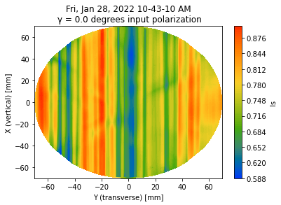
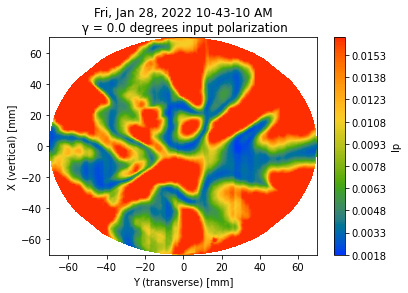
As seen in figures 1 and 2 which show respectively the s and p polarizations normalized intensities the stripes are mainly present in s polarization.
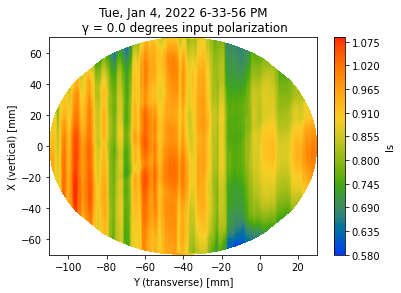
This was not the case for the previous measurements (see figures 3 and 4) were stripes were actually visibles in both s and p polarizations...
Also it seems that p polarization is saturating..
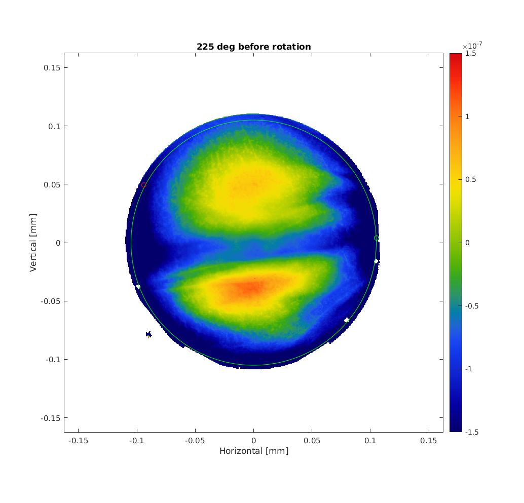
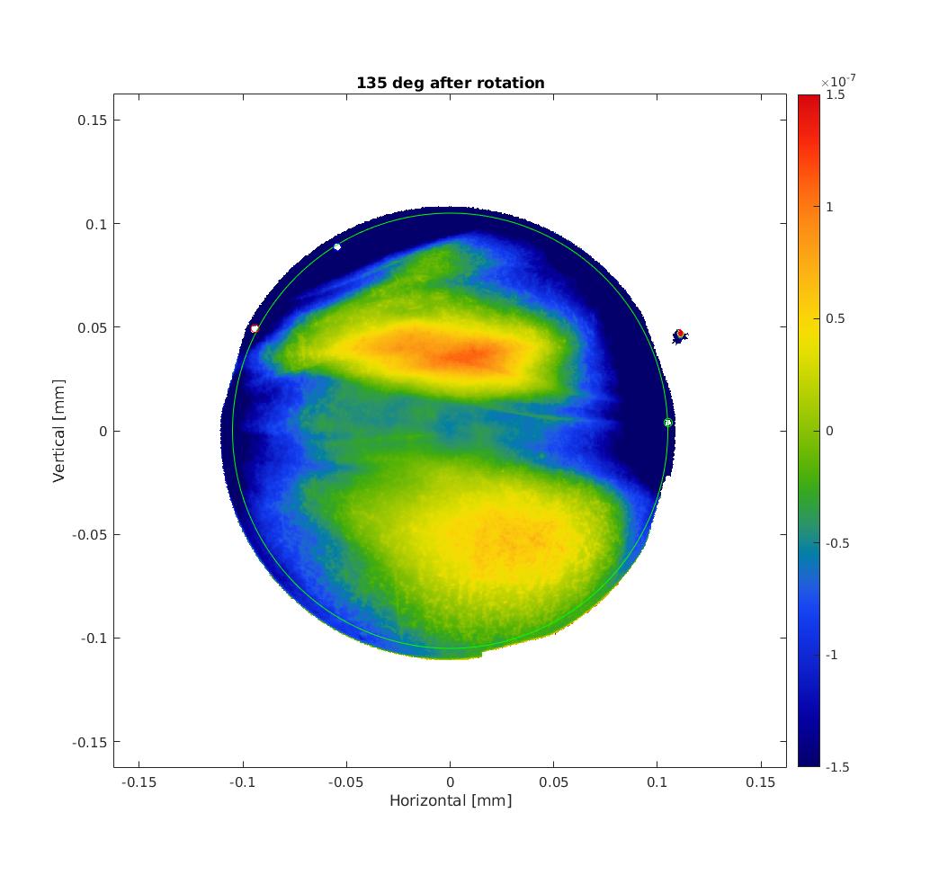
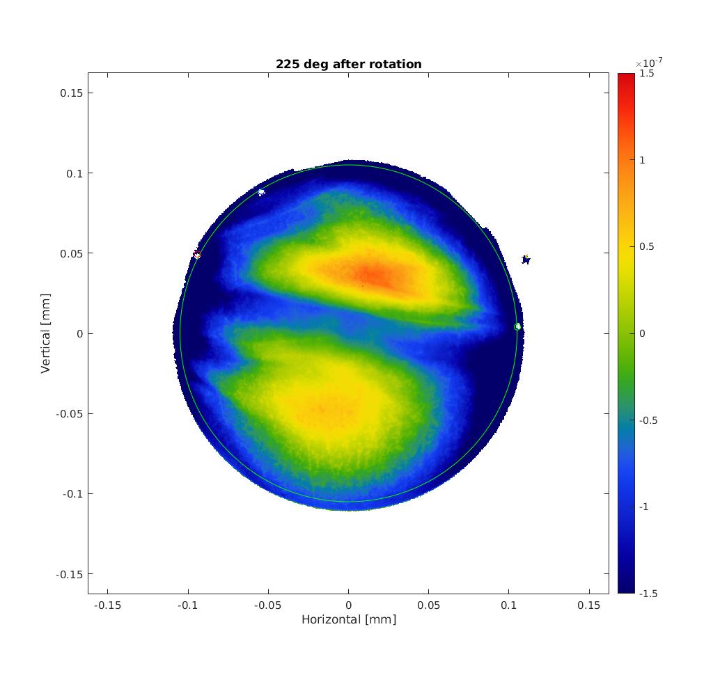
Recently I've been trying to compute birefringence from TWE measurements of spare ETMY based on Aso-san's computation.
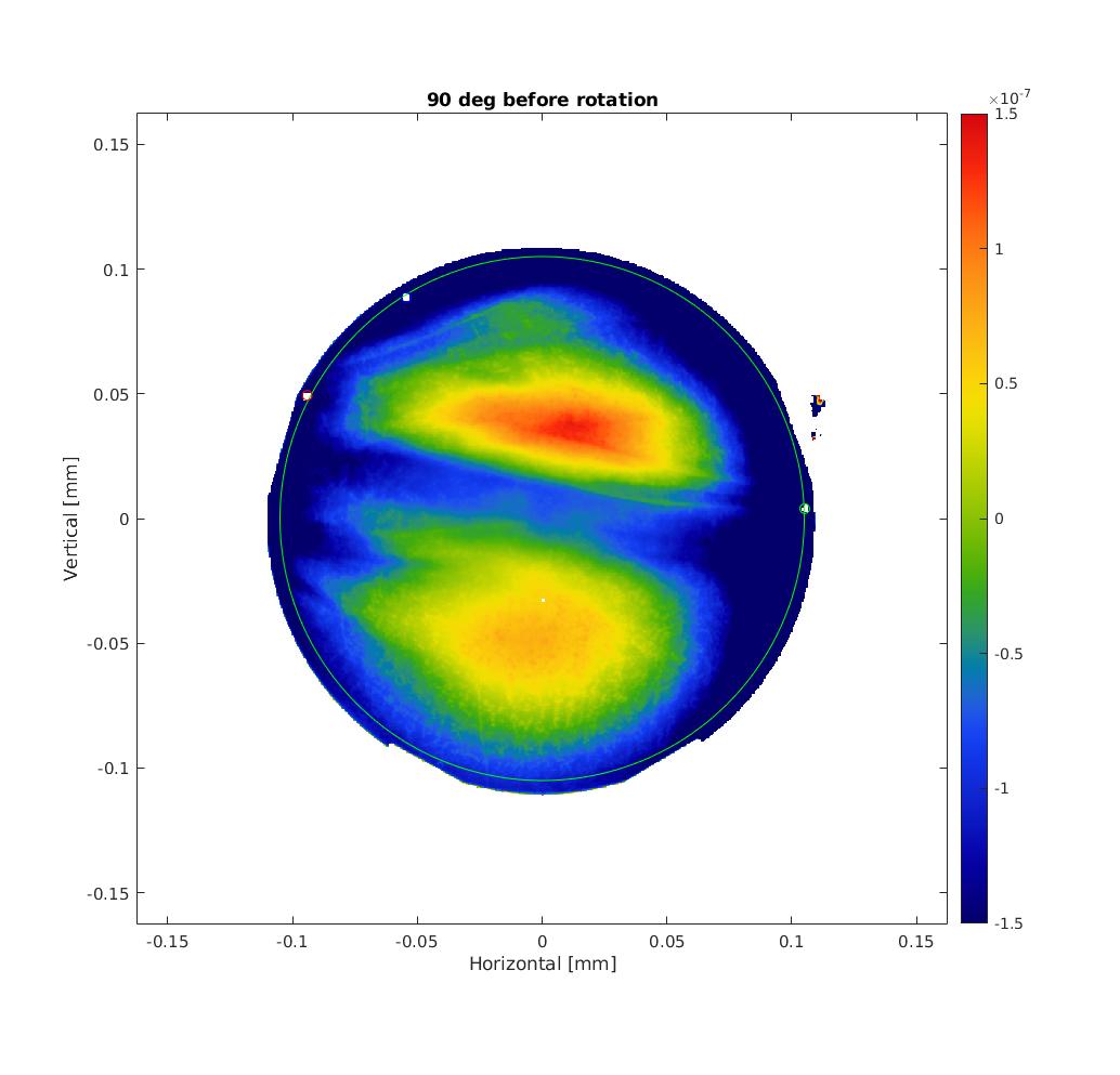
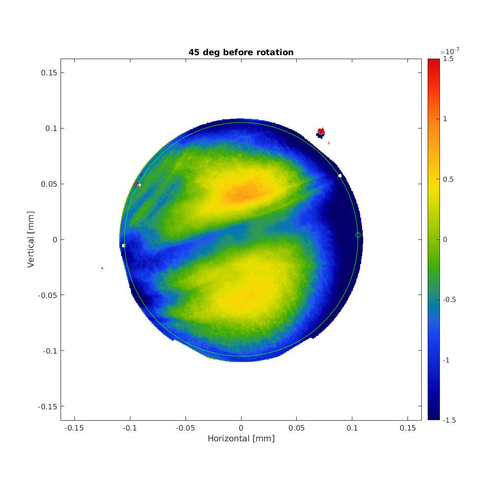
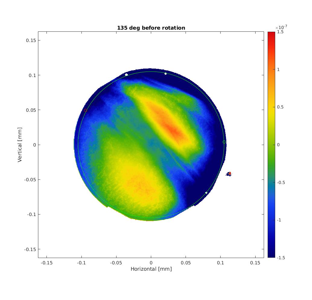
I'm using the S1thruS2 measurements with roll angle of the mirror of 45, 90, 135, 225, 270 and 315 deg with 20 measurements averaged.
The code I wrote does the following :
1) Find the real center and roll angle of each TWE maps
Hirose-san who did the TWE measurements at Caltech placed 3 markers on the mirrors.
First I overlapped 3 circles on the markers of the map with roll angle of 90 deg as it is the same orientation as the PCI measurement.
Then, I changed the centering of all other maps + rotated them to match the circles positions of the 90 deg one.
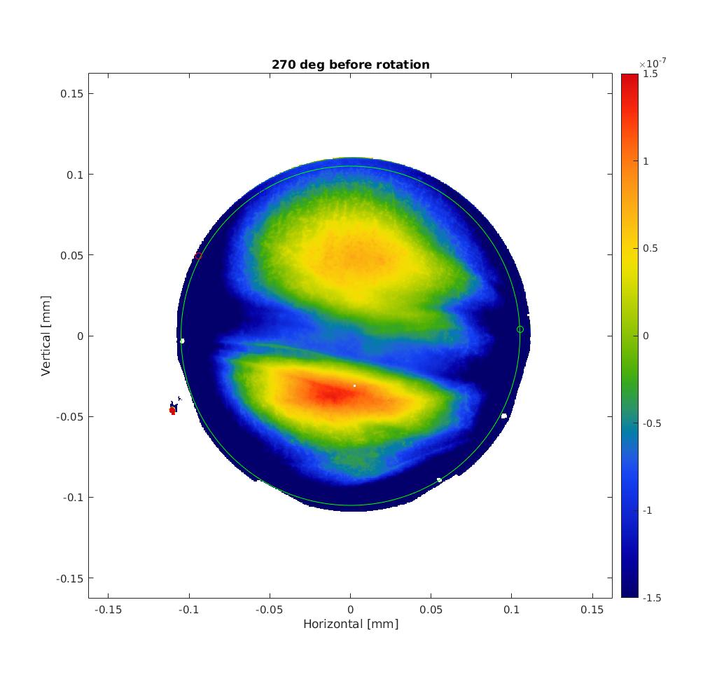
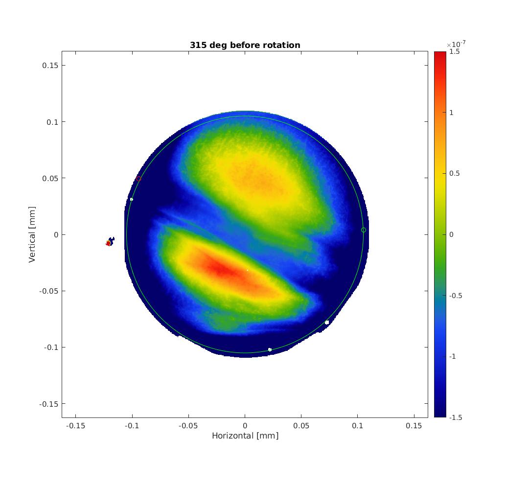
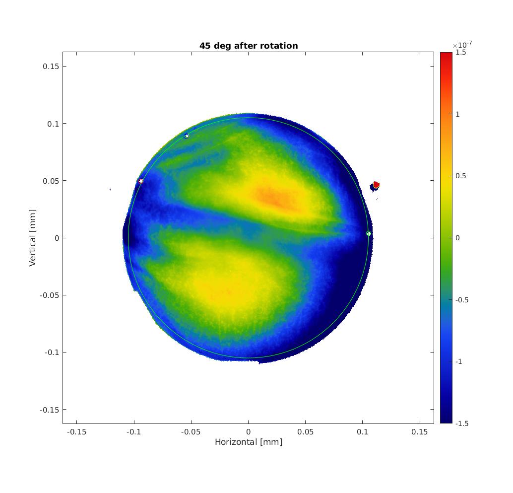
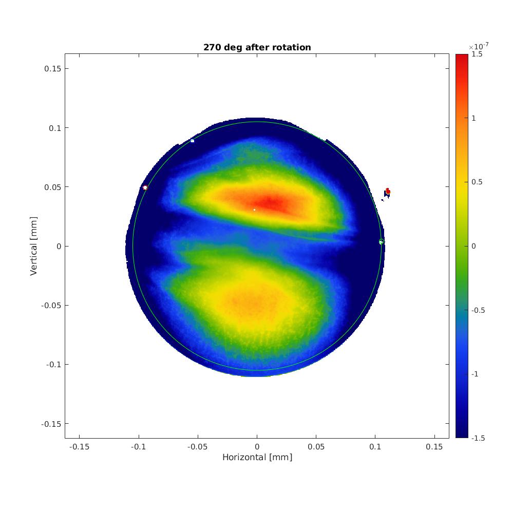
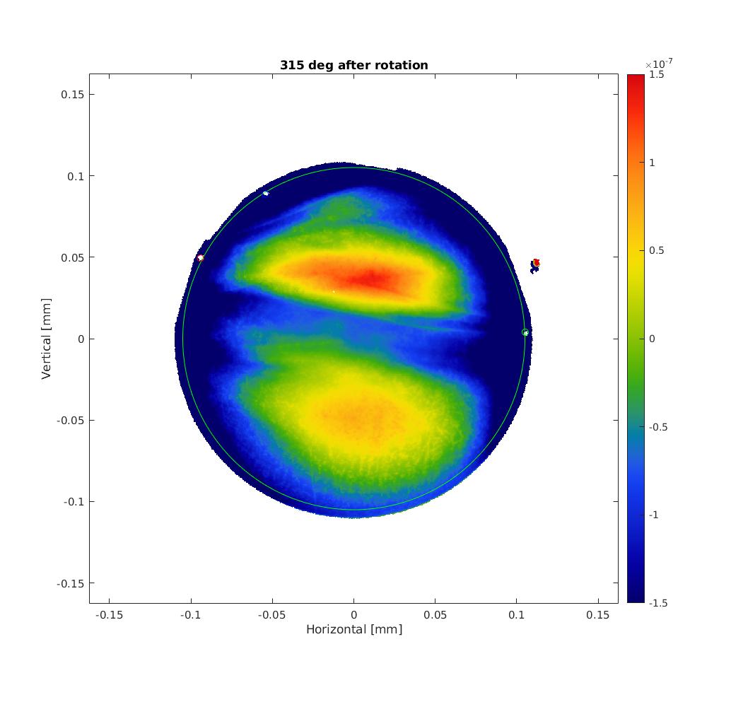
See figures 1 to 6 for the TWE maps (piston, tilt and curvature removed) without rotation and 7 to 11 for the rotated maps.
2) Sanity check of the RoC
OSCAR is used to removed the piston, tilt and focus of the TWE measurements but states that the removed RoC is about -716 m..
This is actually due to the Fizeau interferometer setup. Computing the RoC taking into account the clear aperature and position of the reference sphere gives a mean RoC = 1.9 km (as expected).
Especially, we recovered the same RoC as measured by Hirose-san with 270 deg roll angle.
3) Combining TWE maps into birefringence
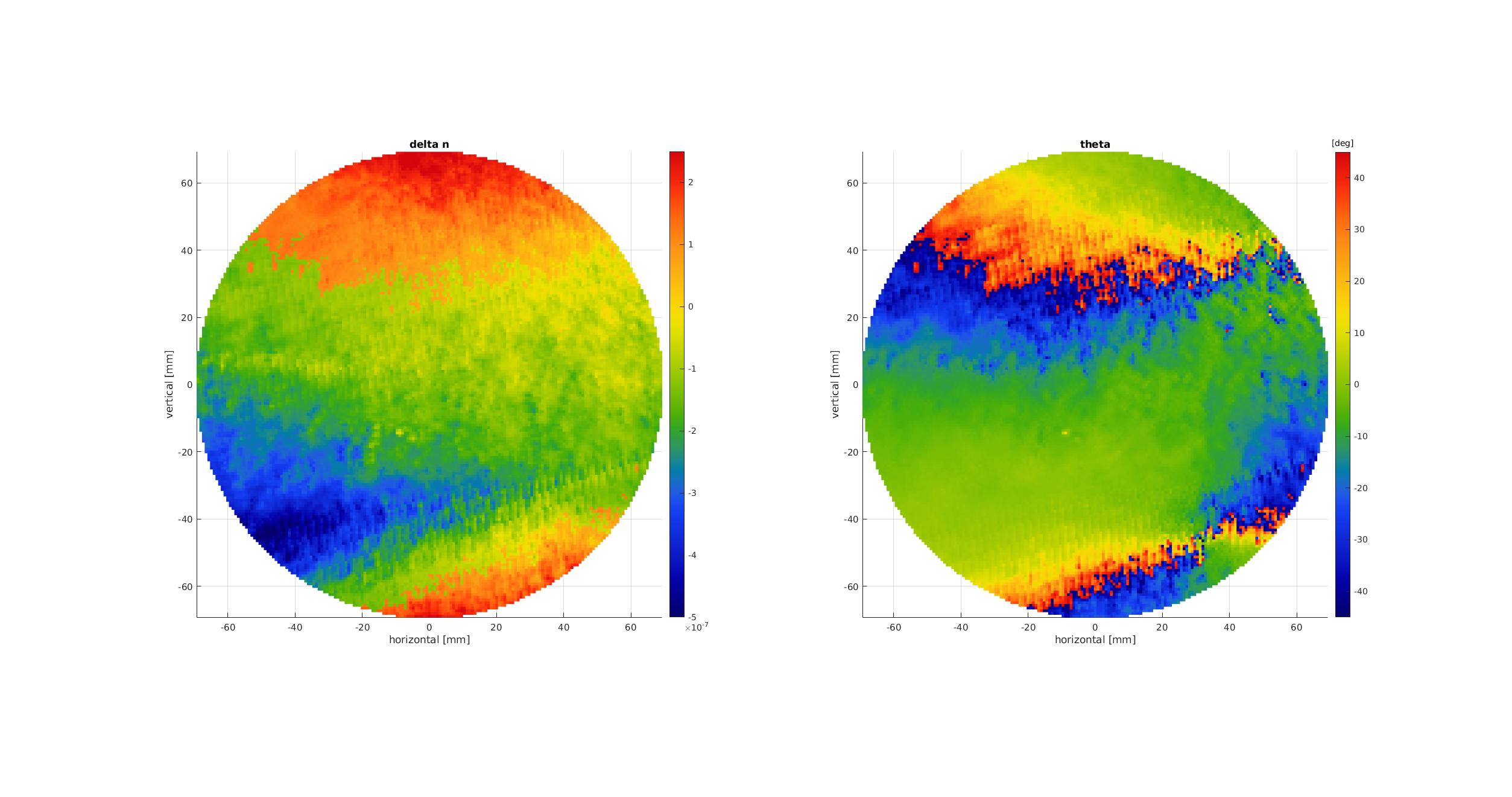
Using 4 rotated maps, it is then possible to compute the spare ETMY birefringence (delta n and theta the fast axis orientation) as in figure 12.
Actually, because there is an arctan(2*theta) used, theta is only defined between -pi/4 and pi/4 that causes some wrapping of theta (and therefore delta n as well).
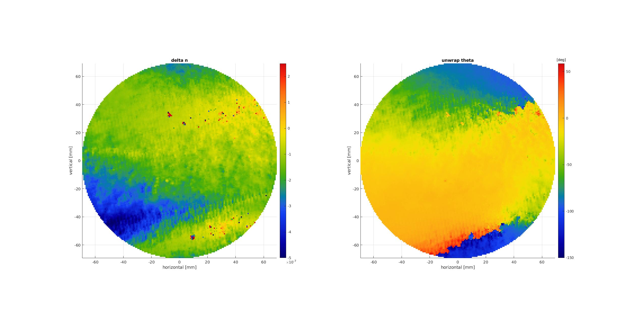
So in figure 13 I used an unwrapping algorithm to try to remove this wrapping. Results are reported in figure 13.
We can recognize so similar patterns to the measurements with the PCI setup. Final conclusion should be done after a new direct measurement with the beam at normal incidence).
4) Next steps
- Tune the unwrapping algorithm -> still some issue at the bottom of the map
- Check the orientation of the mirror during PCI and TWE measurements to understand why there seems to be both a vertical and horizontal flip with respect to each other
- Finalize the direct measurement at normal incidence
For easier comparison with direct measurement with PCI (see elog 2755), I show here the absolute value of delta n flipped both horizontally and vertically .
It seems that the larger delta n area have somehow a close triangular shape.
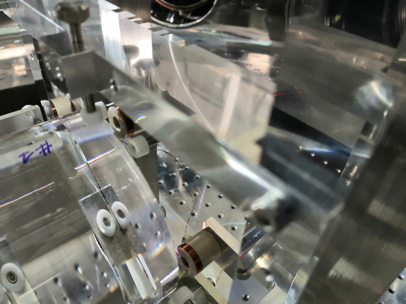
Picture of the mirror without magnets.
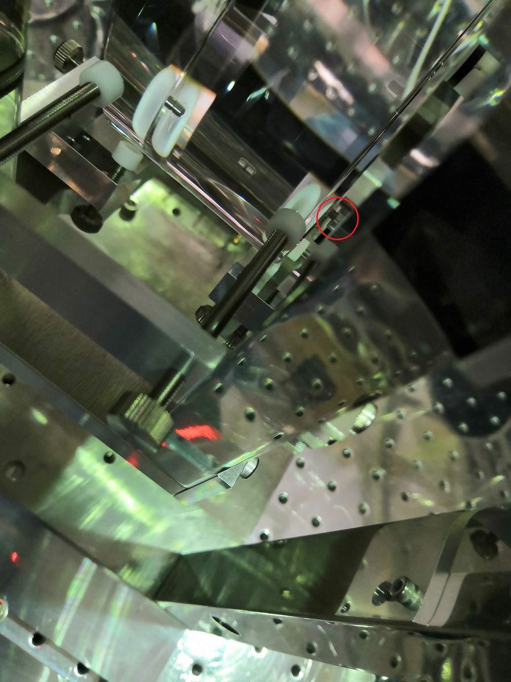
Pictures of gluing.
Since the two magnets of end mirror fell down, this measurement does not make sense. I brought back the rotation angle for END oplev to 0 deg.
[Takahashi, Aritomi]
Since there is a new 6.35Hz peak in END oplev spectra as reported in elog2808, we opened the end chamber and checked the suspension. We found that two magnets of end mirror fell down! This is the reason why the Z correction does not work recently. Takahashi-san will glue the magnets next Monday.
Picture of the mirror without magnets.
One magnet (upper) was glued with the jig and released 3 hours later. The other magnet (left) is under gluing. It will be released on the 14th.
The other magnet (left) was released. The TM was released and the chamber was closed.
Takahashi-san glued the magnet to the input mirror and closed the input chamber. Since it takes one day for the glue to be fixed, we will evacuate the input chamber after tomorrow.
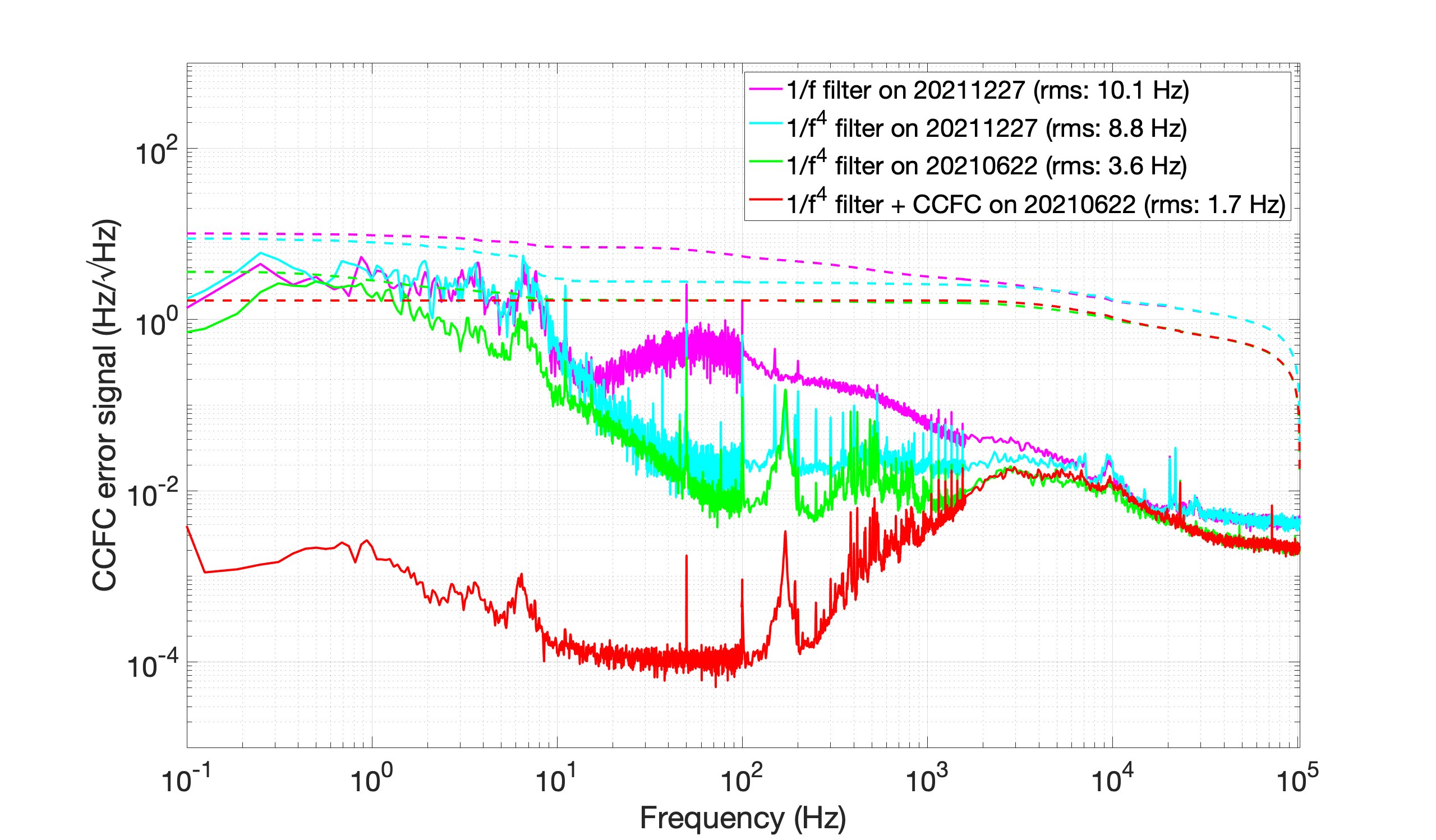
The attached figure shows the CCFC error signal on 20210622 and 20211227. The elogs on 20210622 and 20211227 are elog2597 and elog2770, respectively.
I checked the first measurement of the shinkosha 7 with s polarization at the input,
As shown in figure 1 there are some vertical stripes present in the measurement.
I tuned both the hwp and qwp in the injection and found out that when injecting s polarization, the p polarization readout is minimized for hwp = 0.1 deg instead of previously 1.3 deg.
Then, I also added beam dump to catch the PSD reflections and a small wall to isolate the imaging unit from the injection part.
The beam dump were removed because they are supposed to be used for visible light...
In any case the good news is that we can recognize similar patterns to the previous measurement with tilted beam.
Finally I restarted the s polarization measurement.
I had a look at the normalized Is and Ip data.
As seen in figures 1 and 2 which show respectively the s and p polarizations normalized intensities the stripes are mainly present in s polarization.
This was not the case for the previous measurements (see figures 3 and 4) were stripes were actually visibles in both s and p polarizations...
Also it seems that p polarization is saturating..
I have now taken 3 measurements with s polarization at the input that saturated the lockin amplifier..
It seems that we can really easily saturates the p polarization.
Indeed, it is connected to the old lockin amplifier where the range (0 to 1 V) is changed depending on the sensitivity setting we are using.
Now I'm injecting about 160 uW of power but when doing the measurement with s polarization it seems that the p polarization power changes by more than a factor 14...
I'm starting hopefully the last measurement with s polarization at the input where the sensitivity of the old lockin is set to 100 mV despite the value at the center being 0.2 mV.
It would be convenient to have a new lockin amplifier to avoid this issue...
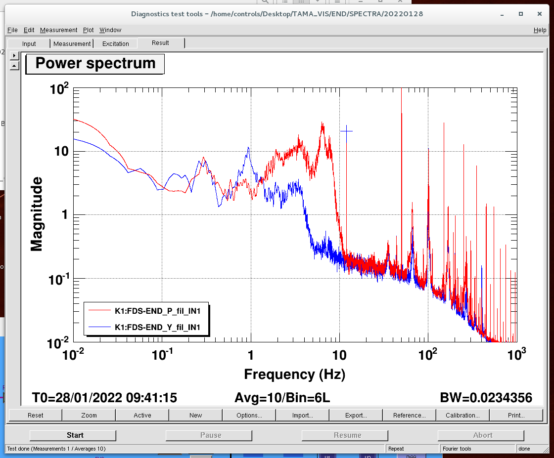
Recently, a 6.35Hz peak is visible in END pitch and yaw oplev spectra (Fig 1). For END oplev diagonalization, I changed the rotation angle for END oplev so that the 6.35Hz peak disappears in oplev yaw spectrum, assuming that the 6.35Hz peak is a natural pitch peak. I changed the oplev rotation angle from 0 deg to 1 deg. The END oplev spectra before/after this rotation are shown in Fig 2 (red, blue: after rotation, green, brown: before rotation).
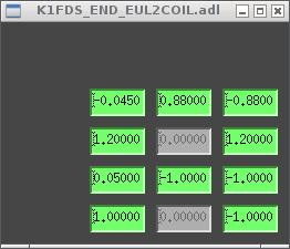
To check END actuation, I put an excitation (12 Hz, amplitude 1000, sine wave) in END length (K1:FDS-END_LEN_ex2). The 12 Hz peak is visible in both pitch and yaw oplev spectra (Fig 3). The 12 Hz peak height was 13.5 and 20.8 for pitch and yaw, respectively. The current EUL2COIL matrix is shown in Fig 4. This matrix might not be optimized for L2P, L2Y coupling.
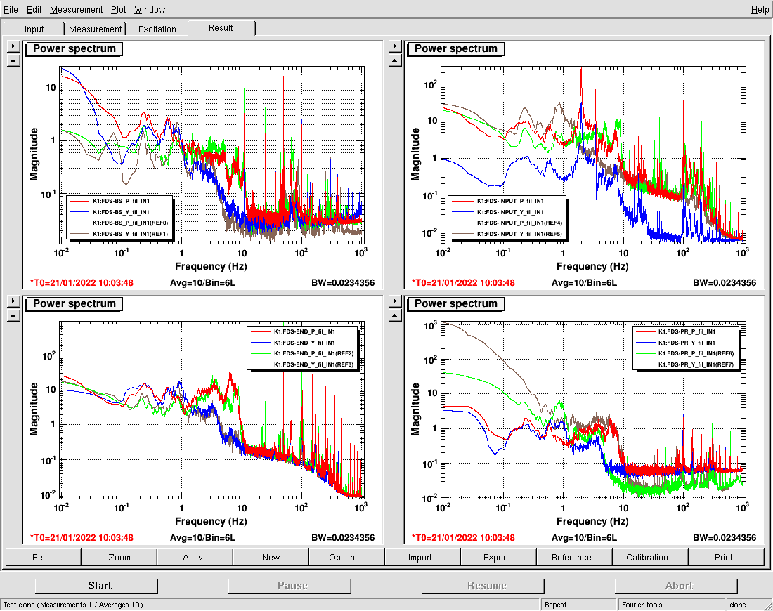
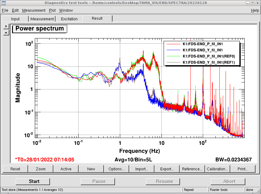
Since the two magnets of end mirror fell down, this measurement does not make sense. I brought back the rotation angle for END oplev to 0 deg.
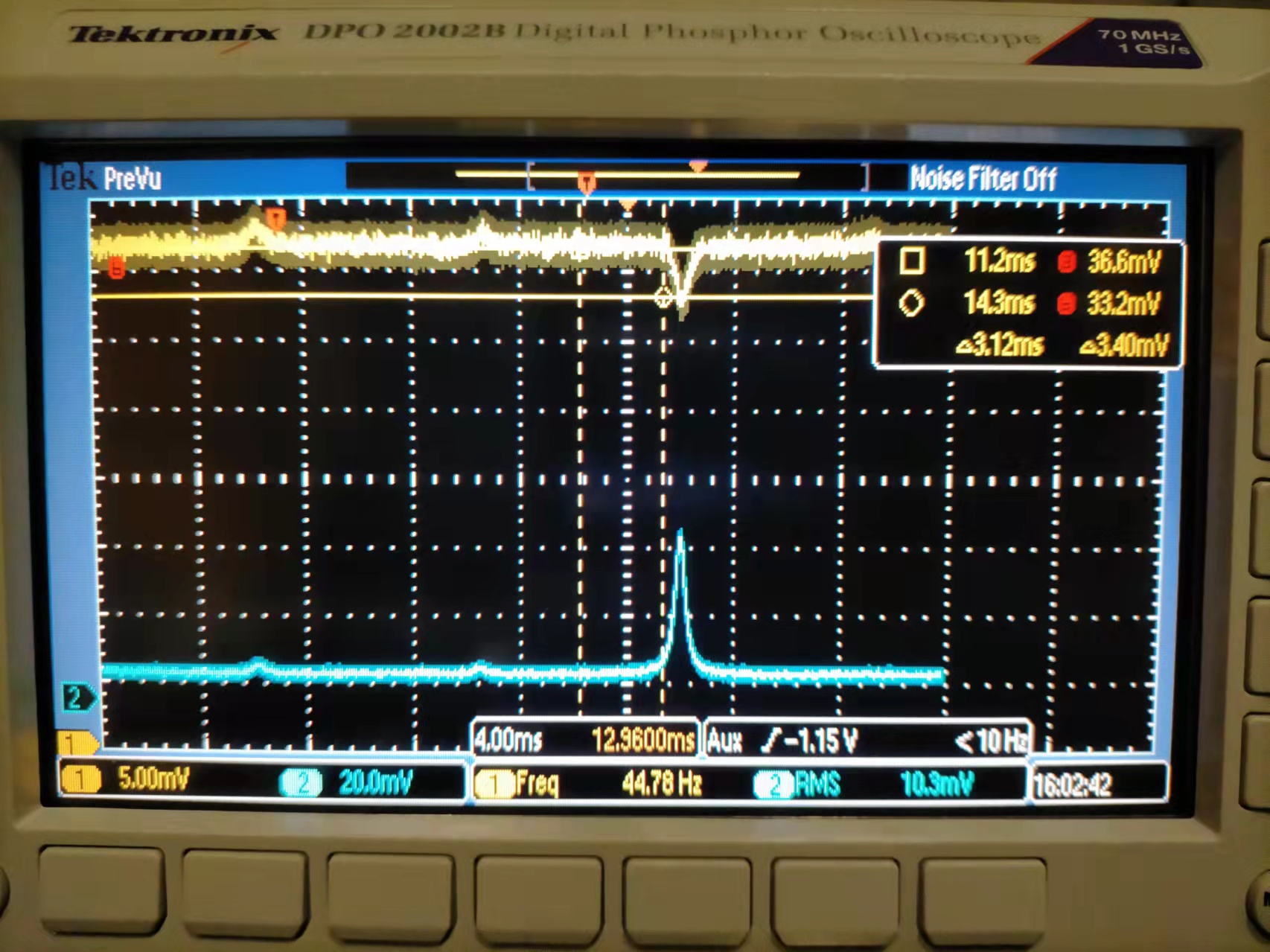
In the case of a rigid cavity, we can estimate internal losses without locking. We just need to scan cavity and look for the reflection signal as shows in Fig.1.
1. We scan cavity and know that about gamma = 5% power is not coupled to cavity for TEM00 resonance.
2. We take the reflected power when cavity is on resonance for TEM00 (33.2mV) and off resonance (36.6mV)
3. We get Rcav = ((33.2/36.6)-gamma)/(1-gamma)
4. RTL = T1*(1-Rcav)/2/(1+Rcav) = 0.206%, here T1 = 0.08. Note: the polishing/coating company (LASEROPTIK) specifies AR coating reflectivity is less than 0.1%.
5. escape efficiency is T1/(T1+L)
In this way, we get escape efficiency of 97.5% for the new OPO.
Katsuki, Marc
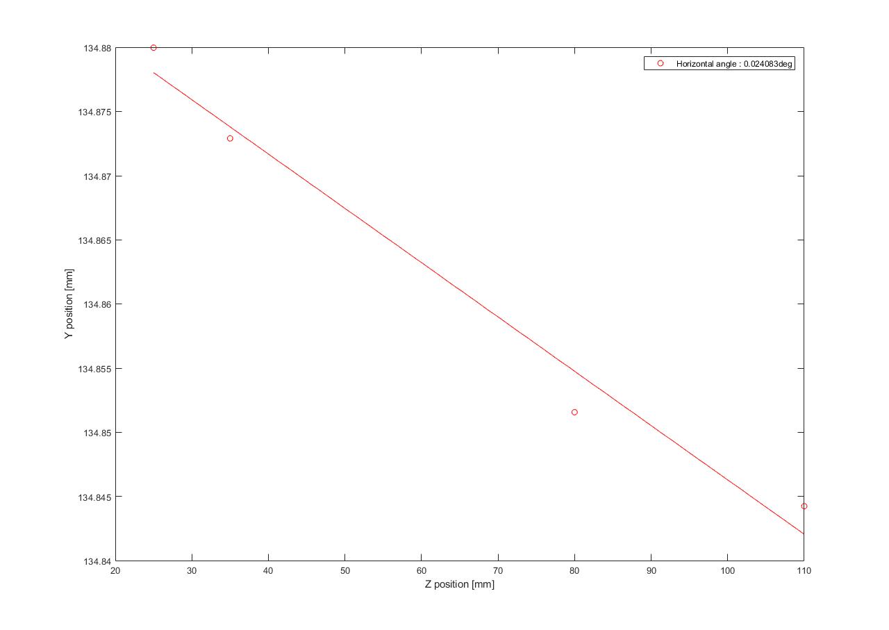
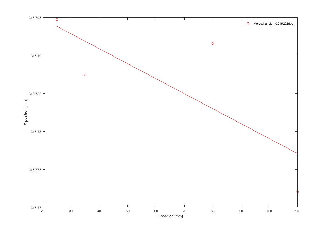
We measured the distance between the blade at z = 25 mm and the last steering mirror.
From this distance and knowing the 2.5deg angle of the beam we found that the beam is hitting this last steering mirror at y = 134.4 mm (in the frame of the translation stage).
We placed the blade at this position and z = 110 mm and tweaked the steering mirror to get half of the power transmitted.
After little back and forth, we measured the horizontal angle of incidence of 0.024 deg and the vertical one to be 0.015 deg.
Because this is more than 10 times smaller than KAGRA requirement on the C-axis angle wrt to the surface normal we can consider that we are now in normal incidence.
We realigned the imaging unit , did the polarization calibration and started the measurement with shinkosha 7 (new center at x = 398 mm and y = 162 mm).
However we are not sure if this substrate has a wedge or not which means that we might see the fringes that Manuel observed...
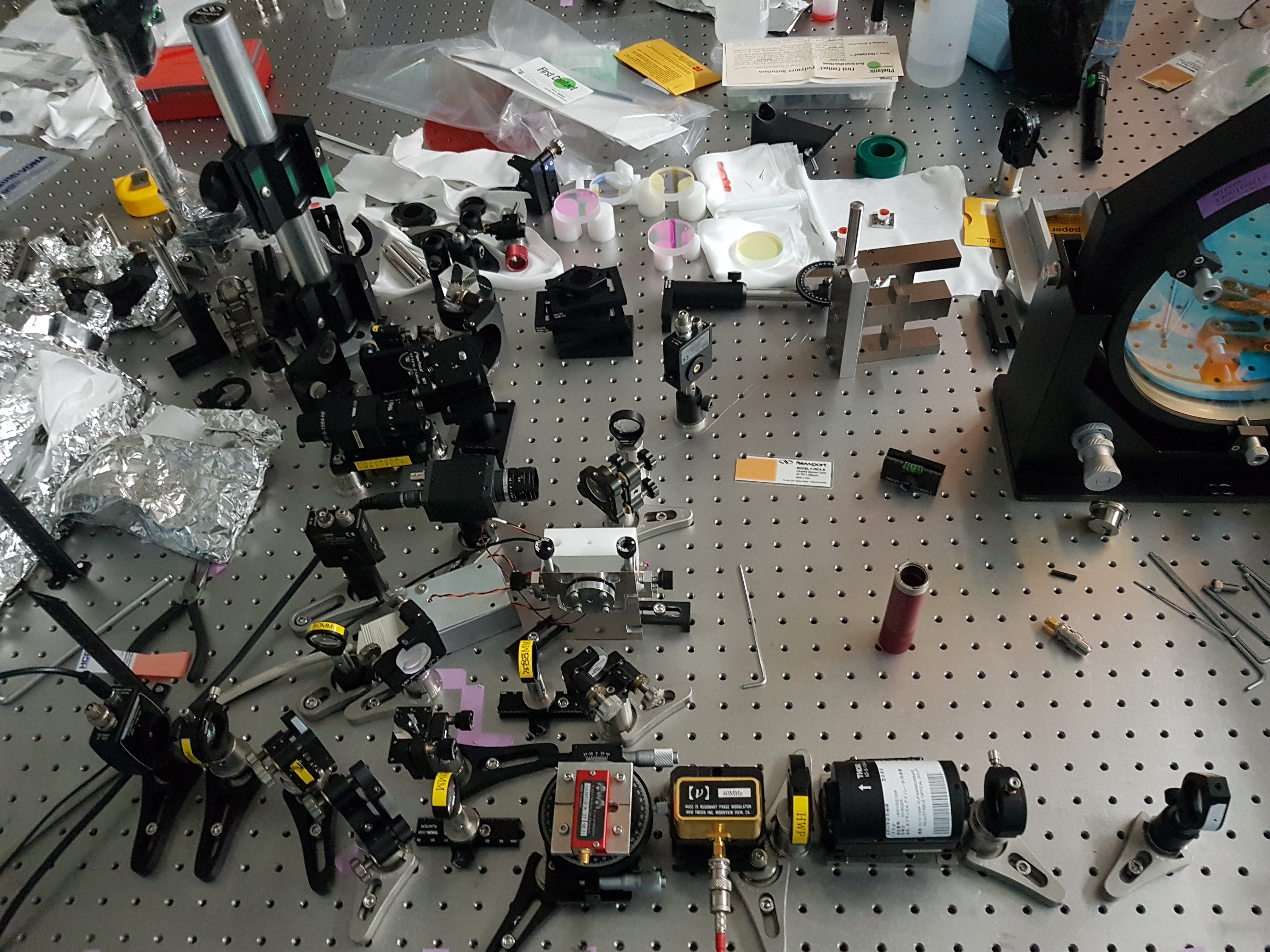
Yuhang and Michael
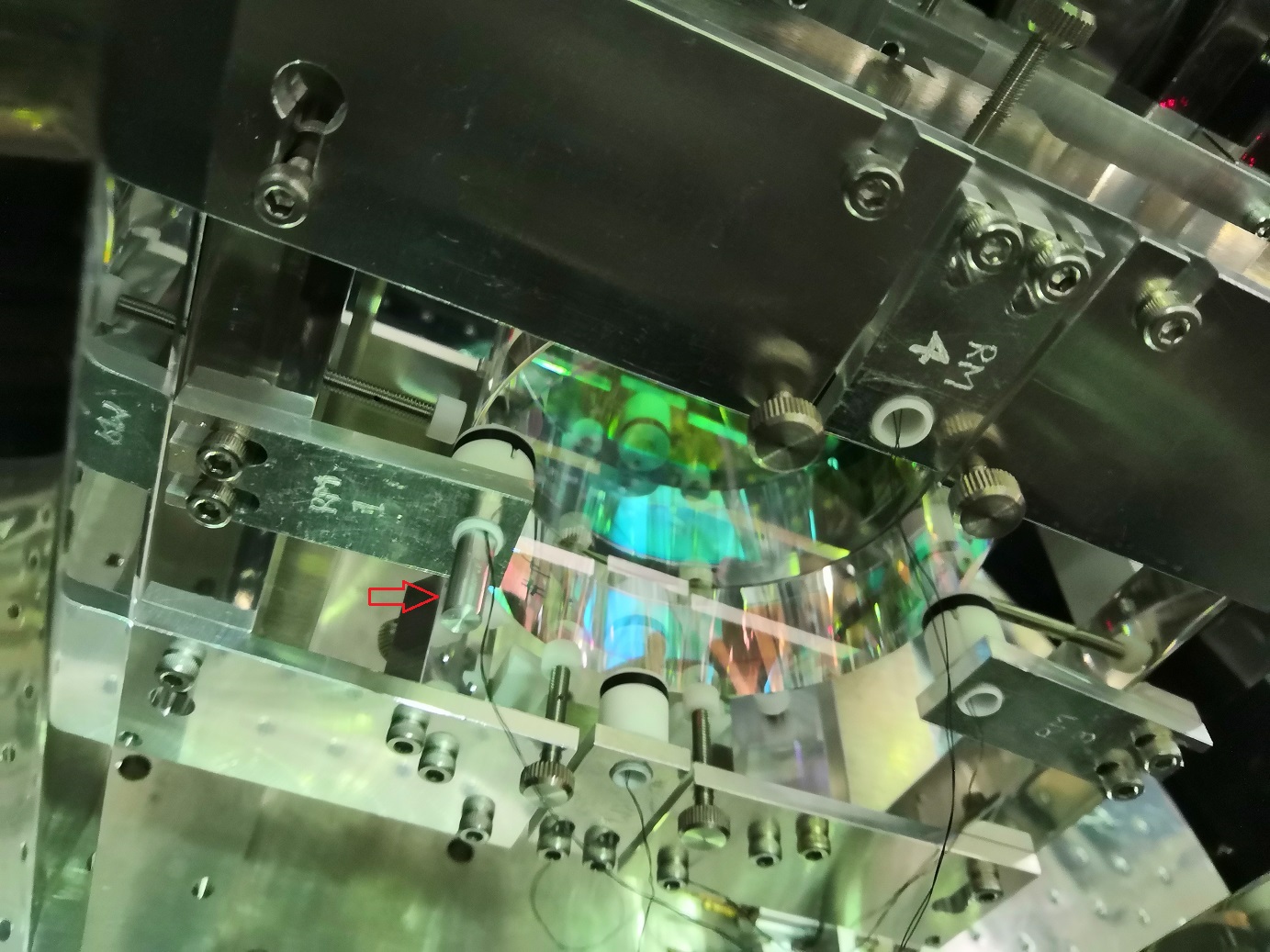
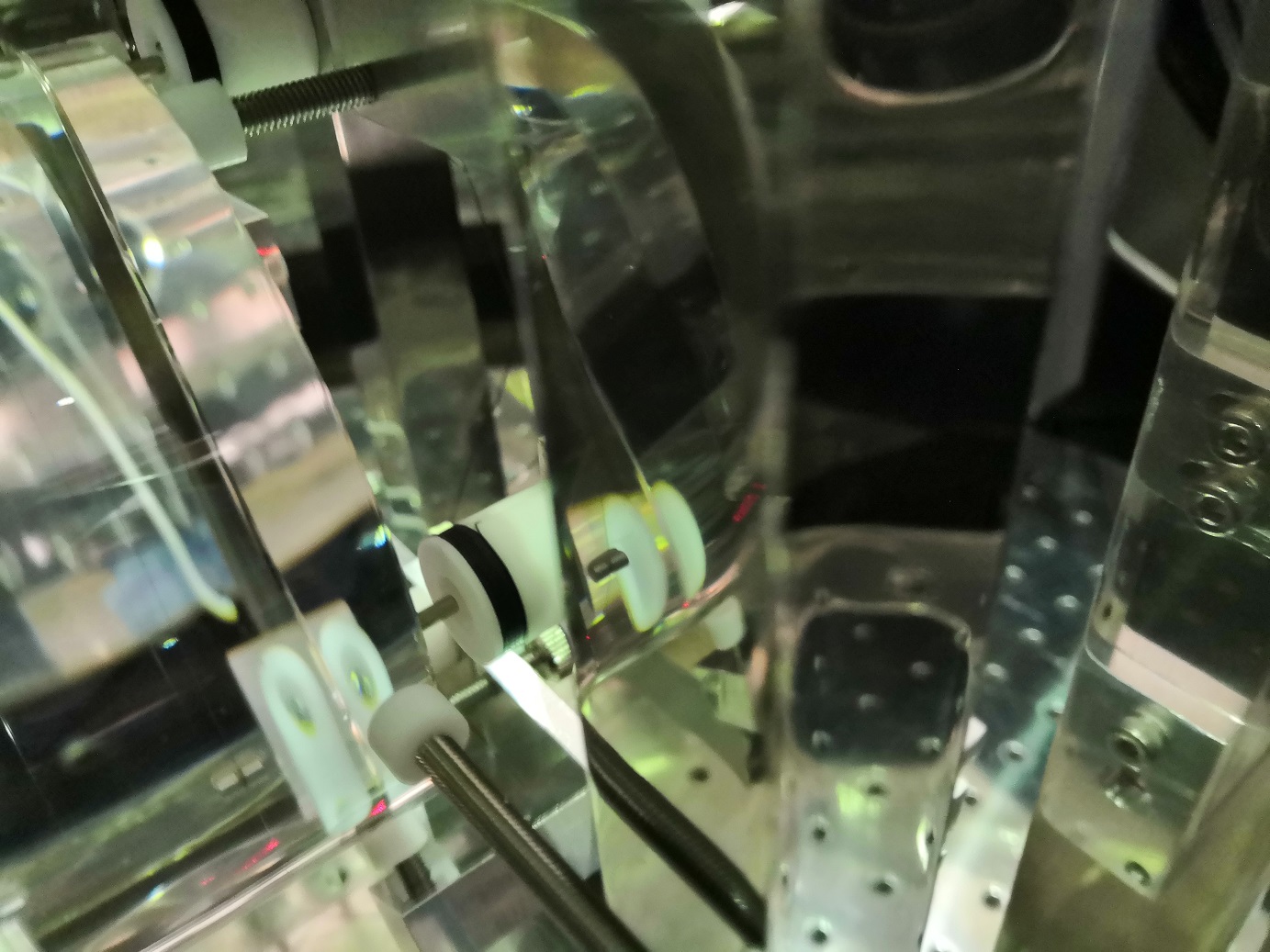
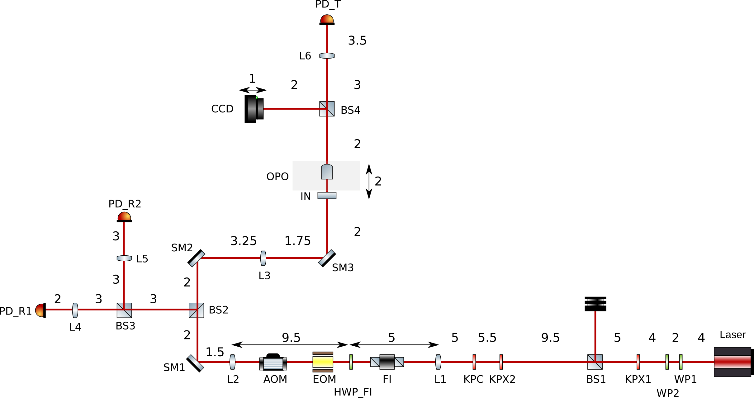
We rearranged the OPO optical layout to use proper photodetectors as mentioned by Yuhang. The layout with breadboard spacing (not to scale) is shown in figure 1. A photo of the setup past L1 is shown in figure 2.
The following components are used. Some of them I'm not sure though:
Laser: Lightwave laser
WP1: ?
WP2: ?
KPX1: KPX094AR.33
BS1: ?
KPX2: KPX094AR.33
KPC: KPC034AR.33
L1: ?
---
Equipment placed for OPO setup
FI: Thorlabs IO-5-1064-VLP
HWP_FI: Half wave plate
EOM: New Focus 4003 Resonant EOM
AOM: AA Optoelectronic MT110 IR 27
L2: f = 40mm
SM1: Steering mirror 1
BS2: 50/50
SM2: Steering mirror 2
L3: f = 75mm
SM3: Steering mirror 3
BS3: ?
L4: f = 30mm
PD_R1: Thorlabs PDA05CF2
L5: f = 50mm
PD_R2: Thorlabs DET10N/M InGaAs biased
IN: OPO input mirror
OPO: OPO assembly block
BS4: ?
CCD: Camera
L6: ?
PD_T: Thorlabs PDA36A
In order to avoid polarization coupling when measuring birefringence with a tilted IR beam (the pump beam) we plan to take future measurement with the pump beam at normal incidence.
Yesterday I removed the last 2 steering optics on the 1310 nm beam path to have enough space to add 2 steering mirrors on the pump beam path.
I also installed a new power meter head (S146C) that has enough range to be used for both absorption and birefringence measurements.
I started by aligning the vertical direction using both a marker on a IR viewing card and iris.
Note that the injection table height is 28 cm with beam height of 5.5 cm and imaging table height is 24.5 cm (so beam height there should be 9cm).
Then I started to align the horizontal direction but it is slightly more tricky as the injection and imaging tables are not aligned.
I installed the razor blade and measured 1.5 deg incidence angle in this plane.
Today we will check the relative position of the blade with respect to the last steering mirror on the pump beam path to fine tune this incidence angle.
Michael and Yuhang
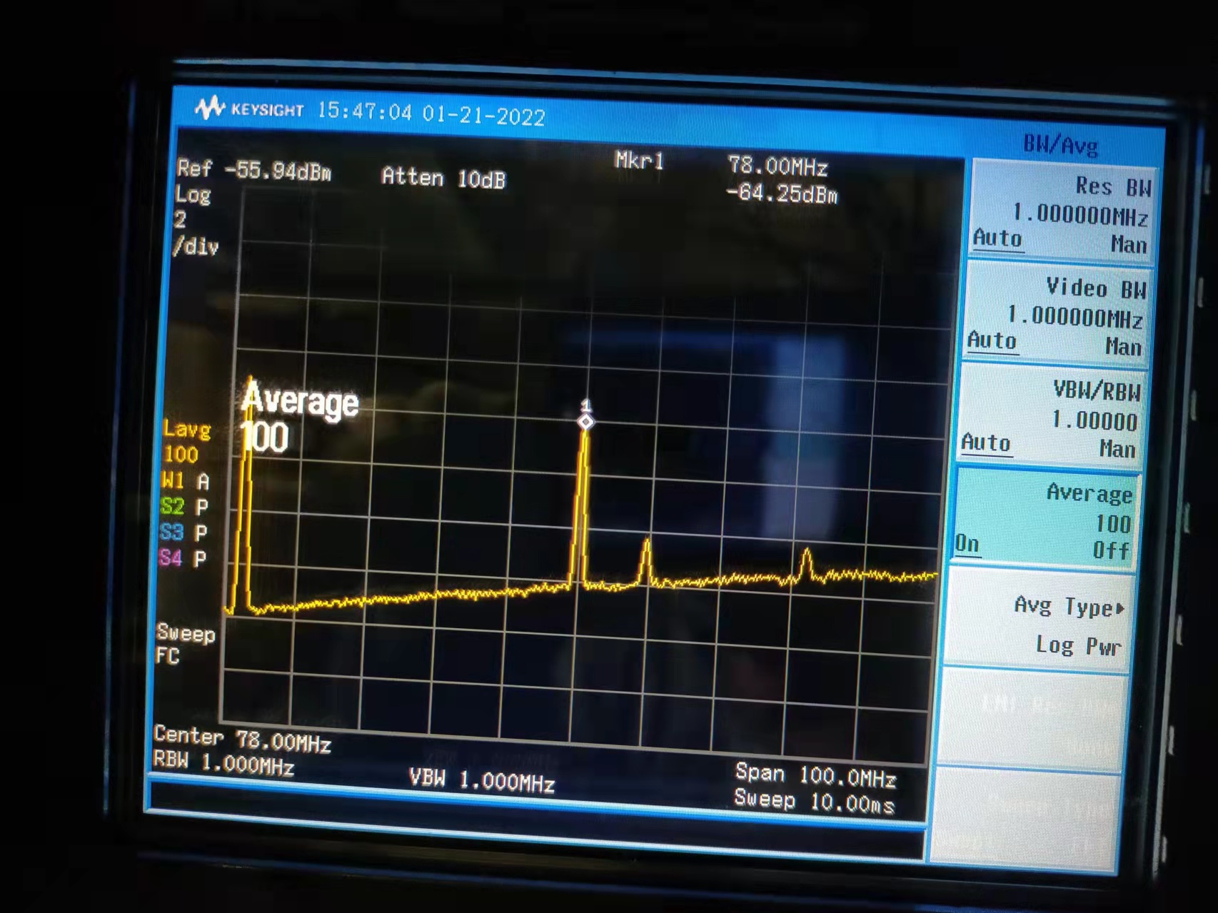
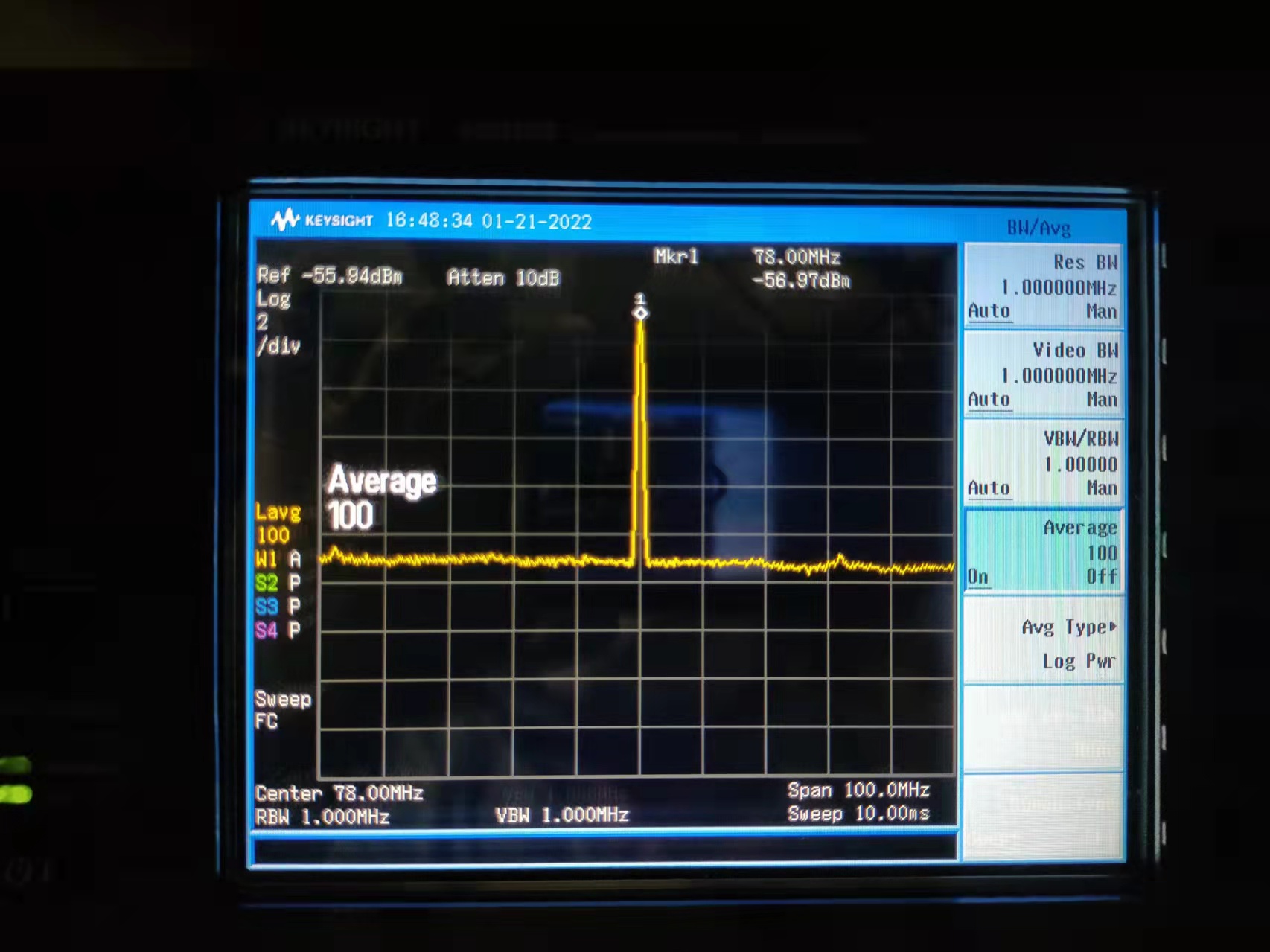
Last week, we replaced two QUBIG PDs for FC GR lock. An RF output only PD is currently used for FC GR lock, which was found to have flat spectrum across tens of MHz as Fig.2. The QUBIG PD with DC and RF outputs is taken out and used for new OPO reflection, which has spectrum as Fig.1. Comparing Fig.1 and Fig.2, we can also find that the RF only PD has a better SNR. However, after a test of DC RF QUBIG PD for new OPO, we found it cannot read phase modulation taken from the reflection of OPO. Although from its specification, PD bandwidth (1-100MHz) is enough to detect 40MHz signal, we decide to not use it since we couldn't find by checking either spectrum directly or demodulated PDH signal. On the other hand, we will use it for monitoring DC response. Considering a BW of 100MHz, which has a very small rise time of 3.5ns.
A PDA05CF2 will be used for acquiring PDH signal for locking. This PD will be placed in the reflection of OPO. It has been proved to be able to provide large enough error signal.
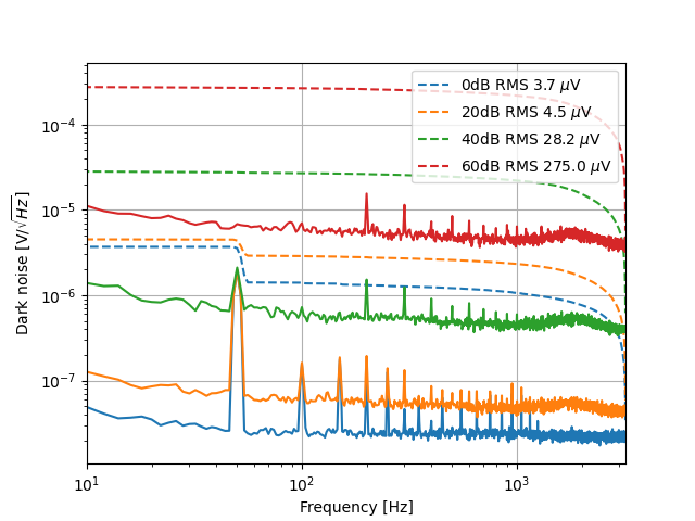
We will use PDA36A-EC in the OPO transmission. If 0dB is enough to measure transmission signal, we can have 10MHz bandwidth, which gives 35ns rise time. However, NIR may have larger rise time since this PD is made of Si. According to Isogai paper, transmission doesn't need fast response. So maybe PDA36A-EC is enough. We will see this later. On the other hand, I took some dark noise measurement, which is summarized in Fig.3. The dB value in the legend shows different chosen gain of this PD. This measurement shows much less dark noise indicated in the specification of this PD. 0dB should be 300uV, 20dB should be 250uV, 40dB should be 340uV, 60dB should be 800uV. One issue is that the RMS I got is only from 10Hz to 3.2kHz. Higher frequency noise must be integrated but I didn't measure. But anyway, we can see that with a factor of 10 gain increase, the noise is not increased by the same factor.
[Takahashi, Aritomi, Yuhang]
Today we opened the input chamber and checked the suspension of input mirror. Because of misunderstanding, we vented not only the input chamber, but also the PR/BS chambers.
Takahashi-san found that one magnet of the input mirror fell down. According to Takahashi-san, the magnet could touch the coil holder and the input mirror could be tilted because of it. In this situation, we tried to recover the tilt by picomotor and then the magnet could fall down. Takahashi-san will fix the magnet and close the input chamber next Monday.
After Takahashi-san adjusted the suspension, we could move the picomotor for input mirror and the green reflection overlaps with the injection now.
Finally, we started to evacuate the PR/BS chambers.
Takahashi-san glued the magnet to the input mirror and closed the input chamber. Since it takes one day for the glue to be fixed, we will evacuate the input chamber after tomorrow.
Pictures of gluing.
I started the evacuation of input chamber. First I used rotary pump until the pressure in the input chamber reaches below 0.1mbar. After I removed the rotary pump, I closed the small gate valve close to arm and opened the small gate valve close to the input chamber. I will wait until the pressure in the input chamber reaches the similar one in the BS chamber.
Before I opened the gate valves between input/BS and input/arm, the pressures in input, BS, arm was 1.3e-6 mbar, 9.9e-10 mbar, 3.1e-8 mbar, respectively.
First I opened the gate valve between input/BS. After 1 hour, the pressures in input and BS chambers became 5.5e-7 mbar and 1.9e-8 mbar, respectively.
Then I opened the small/large gate valves between input/arm. The pressures in input, arm became 5.4e-7 mbar,4.5e-7 mbar, respectively.