NAOJ GW Elog Logbook 3.2

As reported in elog2801, we replaced a PD for FC green lock. The new PD has only RF output, but has better SNR. First I checked the PDH signal of FC green lock with the new PD and found that the demodulation phase was not optimized. I changed the demodulation phase of FC green lock (DDS2 CH1) from 354.99 deg to 270 deg. I saved this DDS2 setting as 20220215_dds2.stp.
The FC could be locked with gain of 2.4 for 1/f filter and 0.8 for 1/f^4 filter. The injection green power was 21.1 mW. Since the FC servo gain becomes half with the new PD compared with old PD reported in elog2770, the new PD seems to have larger gain by a factor of 2.
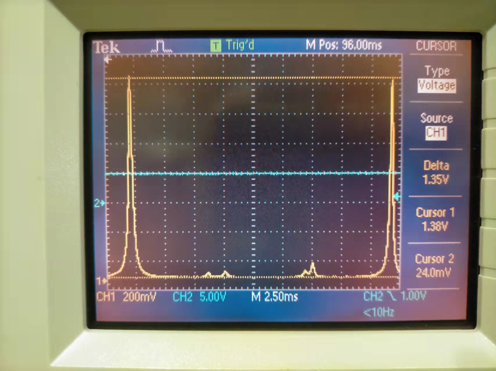
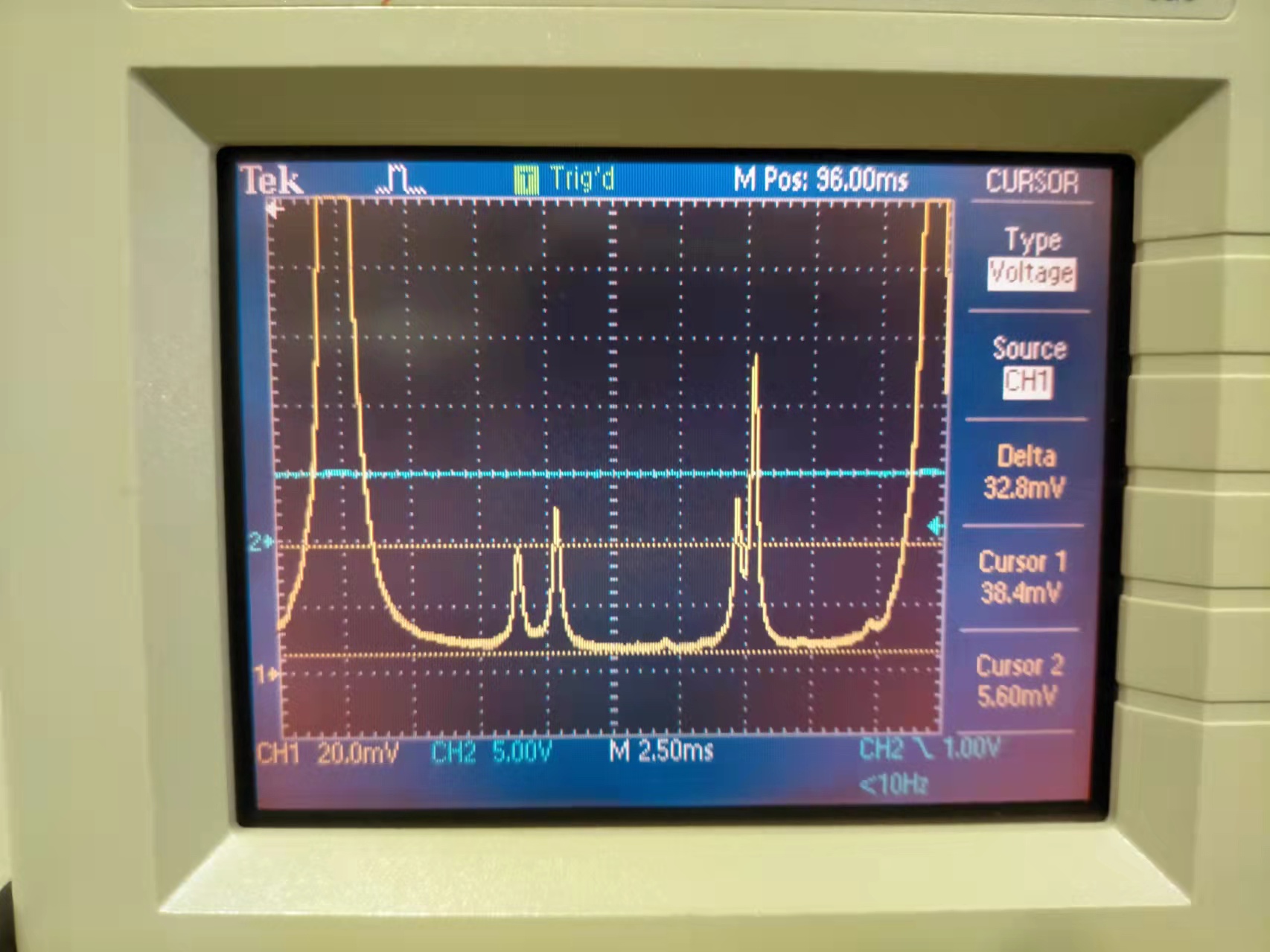
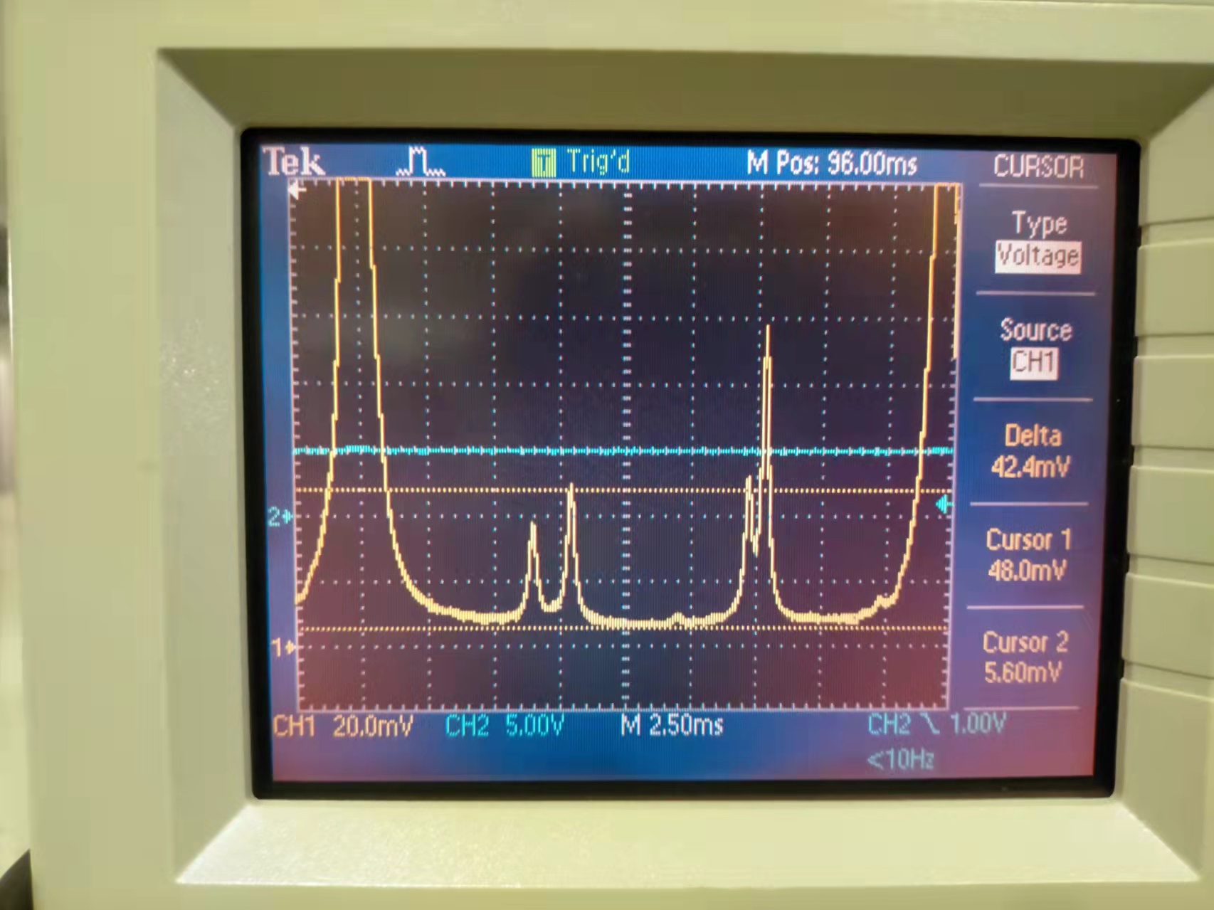
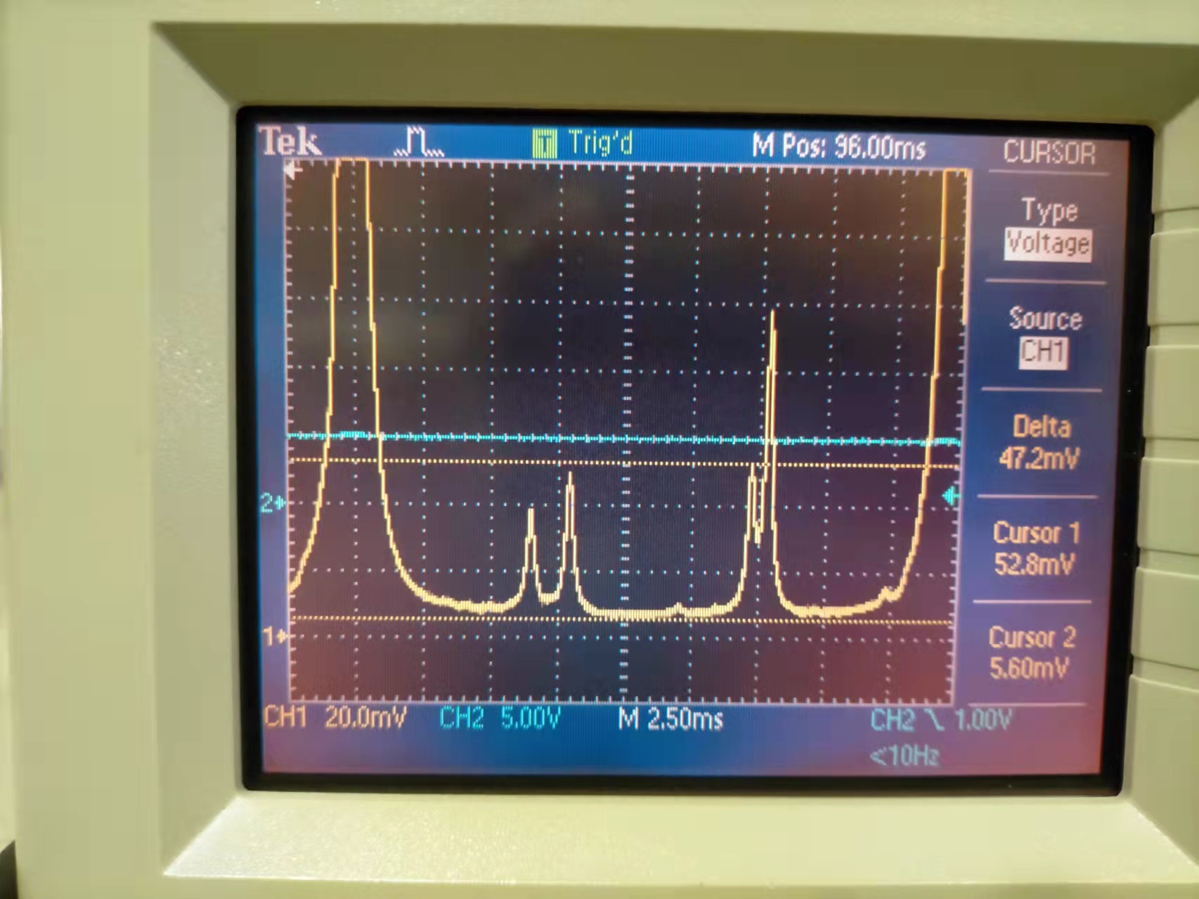
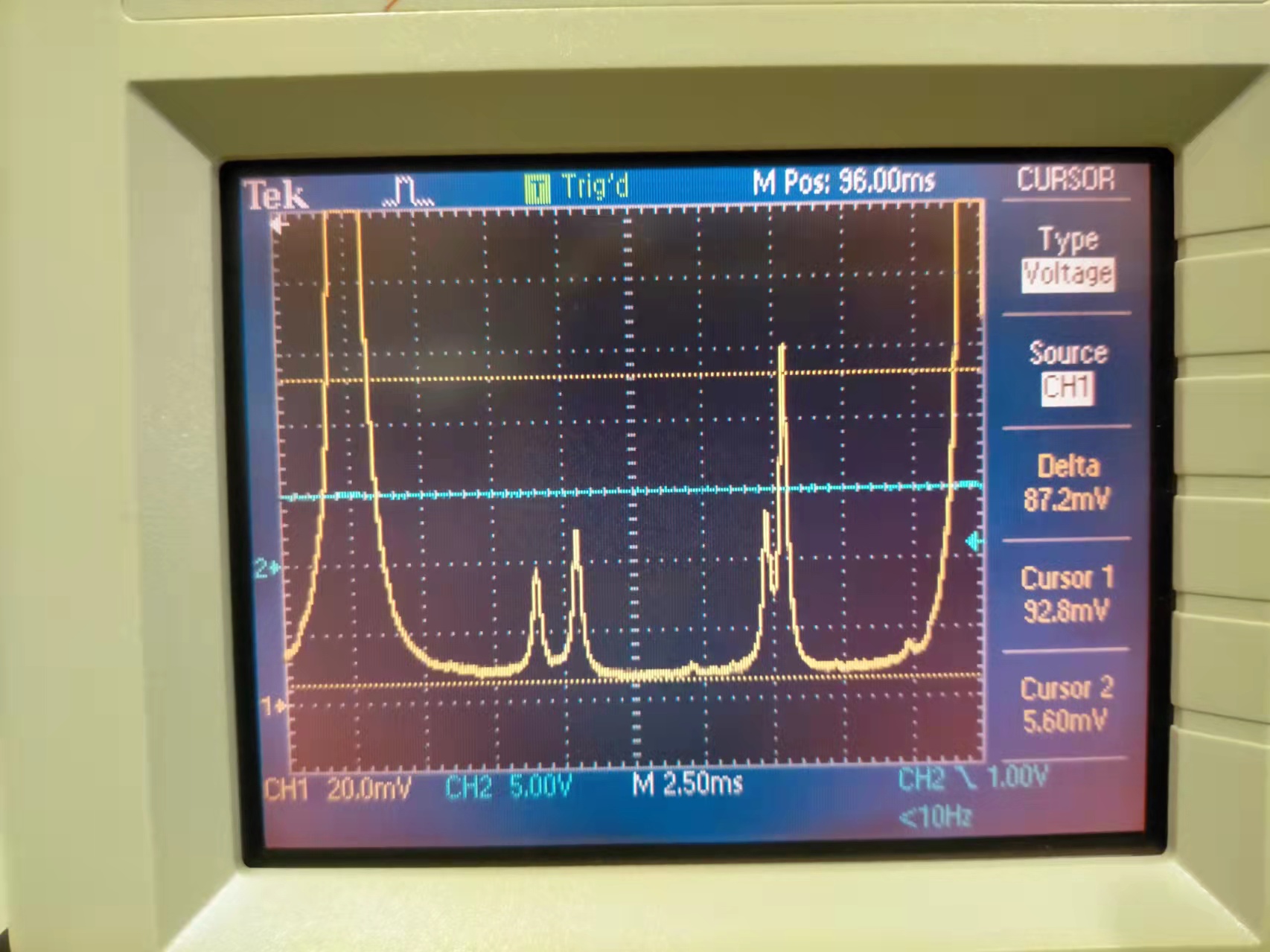
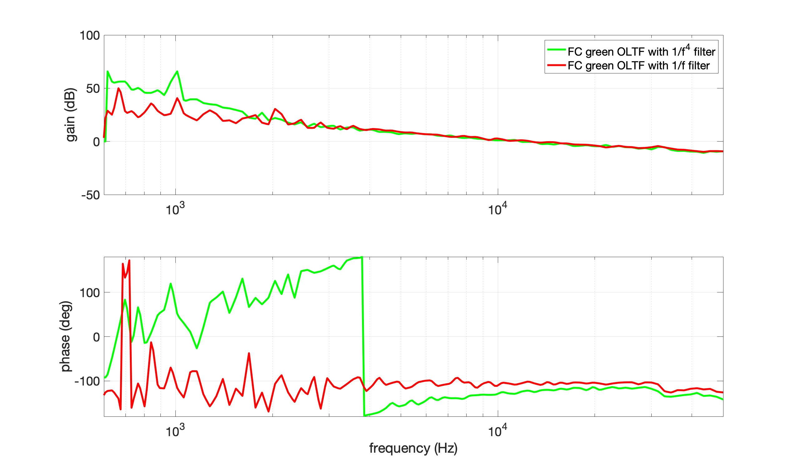
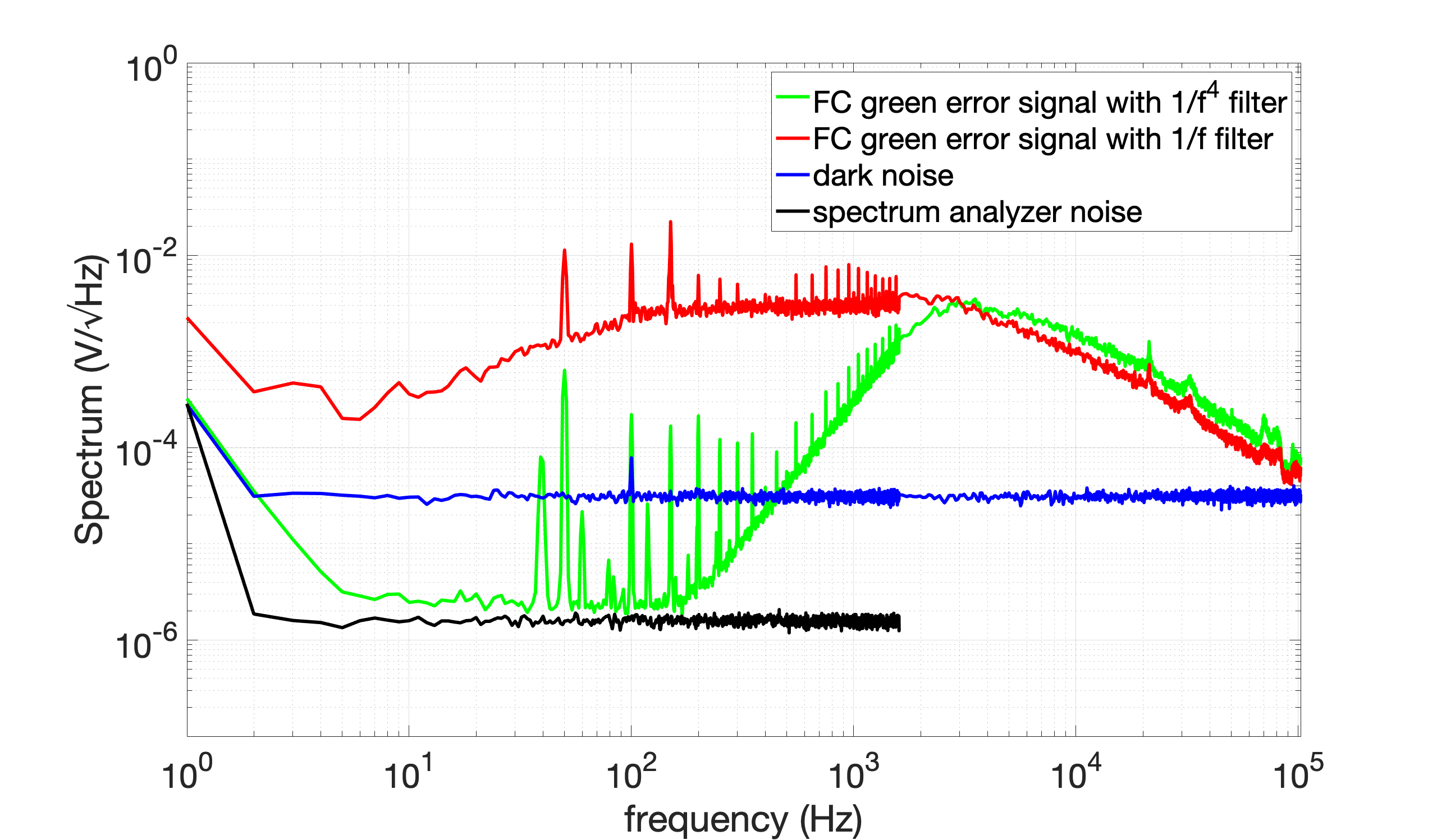
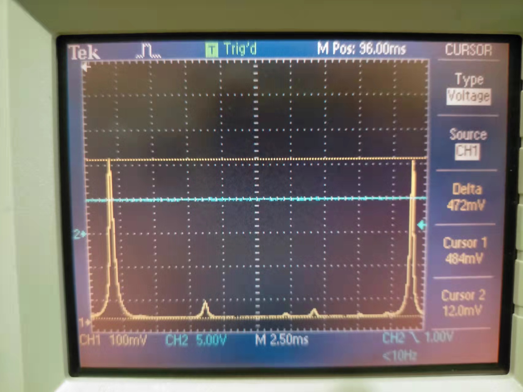
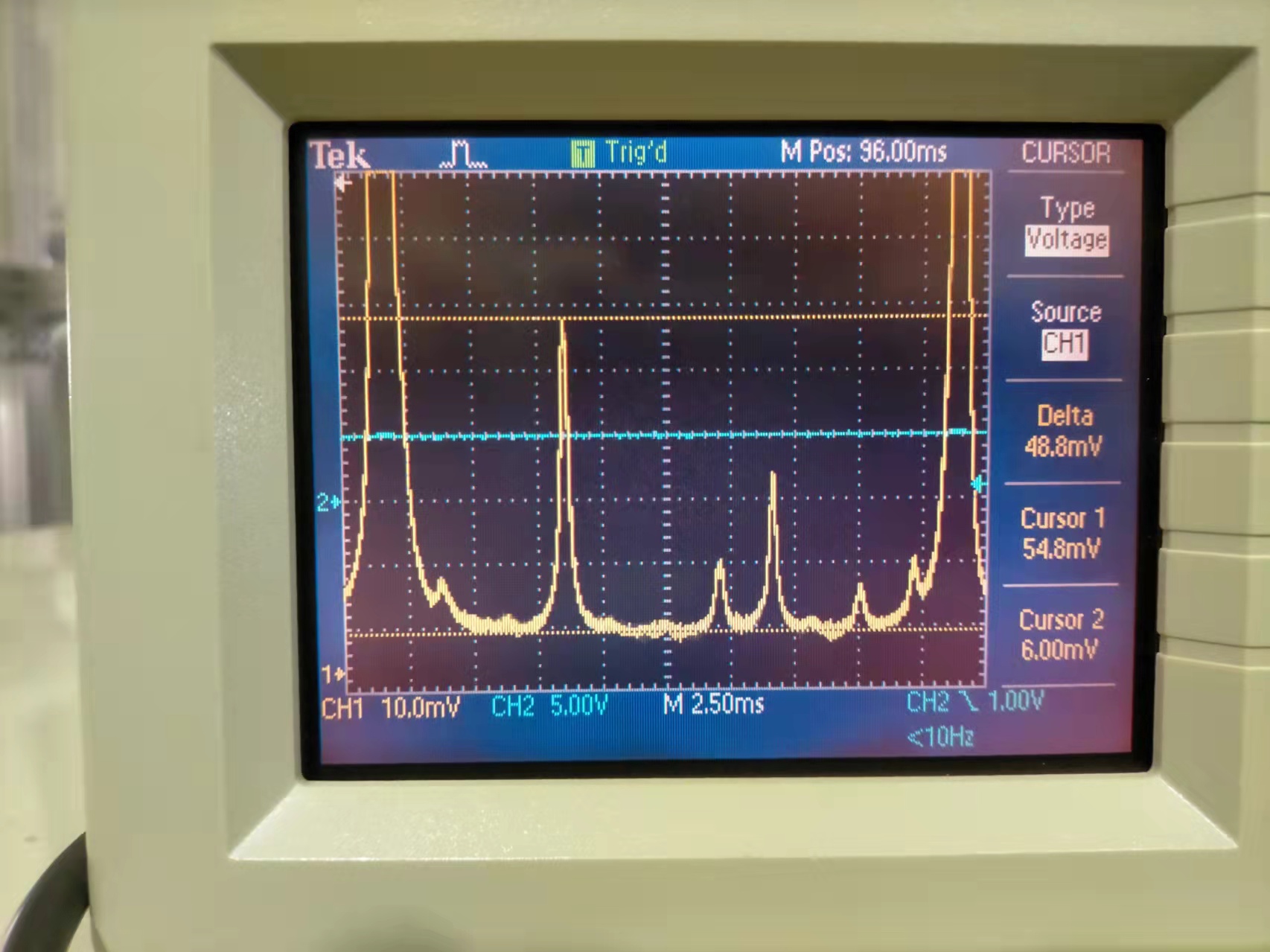
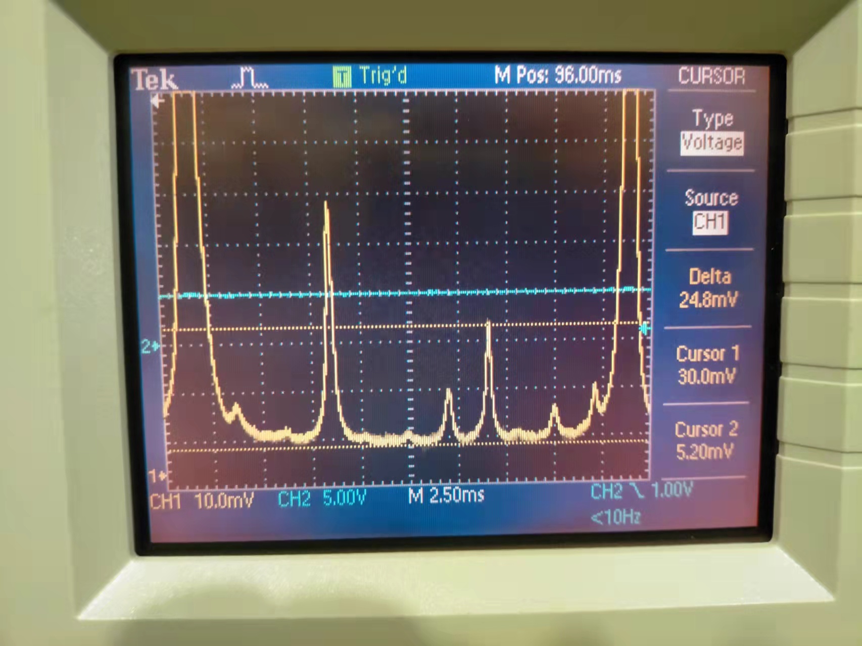
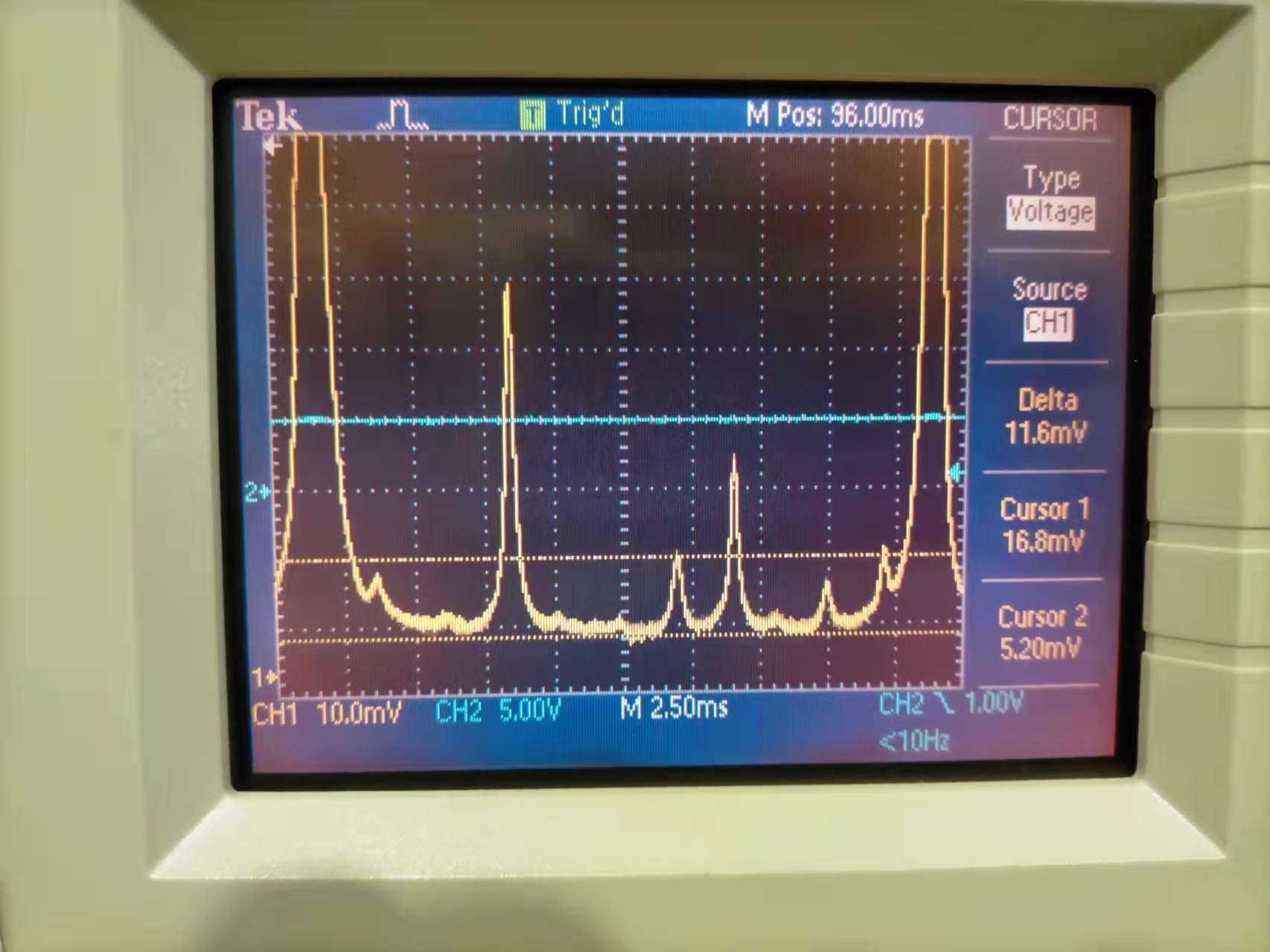
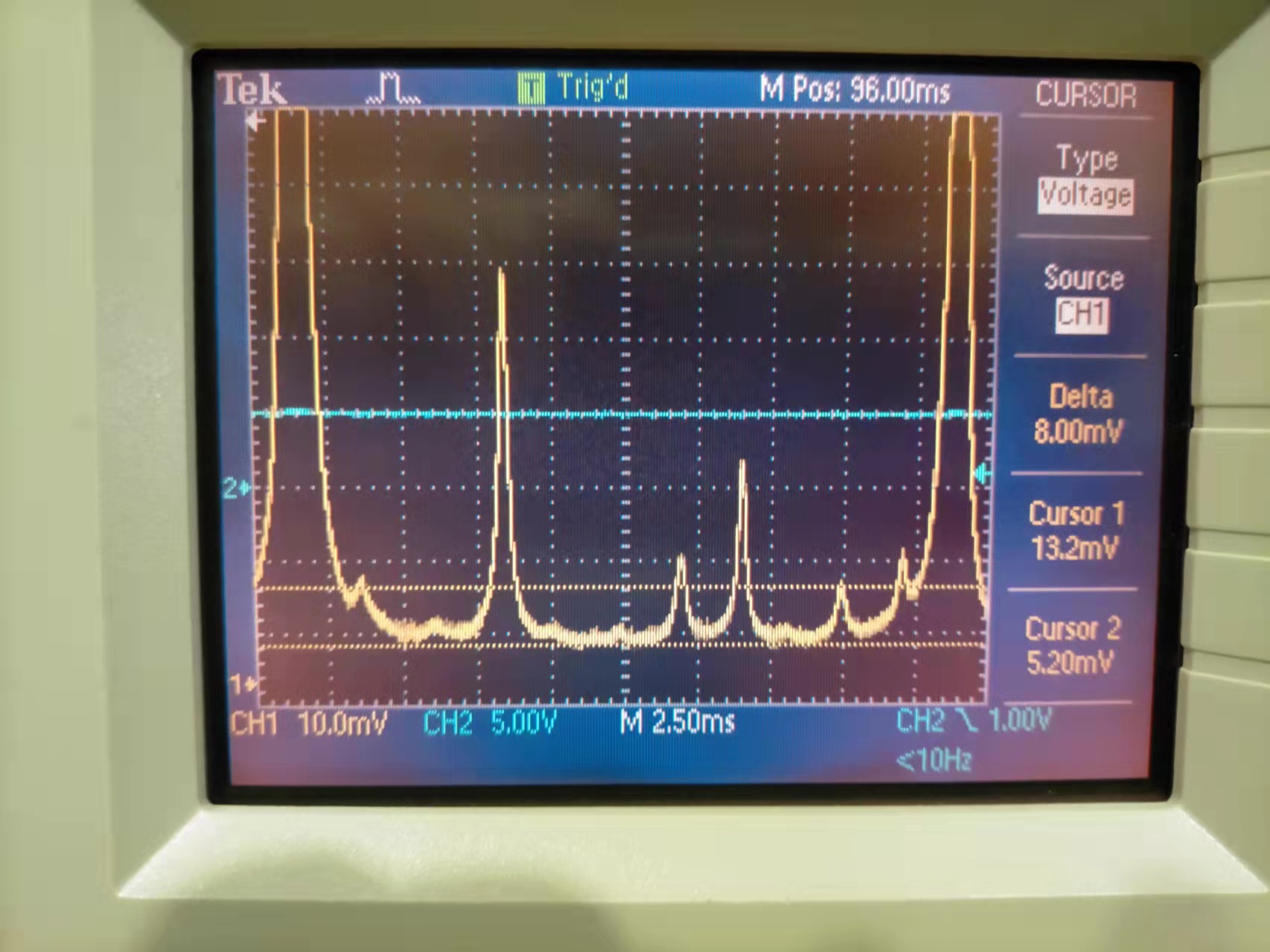
Then I measured OLTF and error signal (EPS1, 1Vpp fixed range) of FC green lock with 1/f and 1/f^4 filters (Fig. 1,2). Both UGF are around 12kHz. The dark noise with new PD is 3e-5 V/rtHz, while the one with old PD is 2e-5 V/rtHz as shown in elog2770. Since the signal of new PD is 2 times larger, the SNR of new PD should be better than that of old PD.
There are many harmonics of 50Hz. These harmonics are not present in dark noise, so they should come from green.
During this measurement, Z correction with gain of 10 was engaged. BS pointing and AA were not engaged since they are unstable. We should investigate these loops.
I tried to move END YAW with motor A, but it didn't move. Maybe the motor A is also broken.
Today I opened the gate valves between END/arm. The pressure in END and arm before I opened the gate valves was 8.7e-7 mbar and 9.4e-8 mbar, respectively. After I opened the gate valves, the pressure in END and arm became 6.6e-7 mbar and 1e-6 mbar, respectively.
After the END mirror alignment with picomotor, we finally recovered the green flash!
Katsuki, Marc
We installed the new ion gun and used it to clean shinkosha7 surfaces.
We removed the first steering mirror after the lens and realigned the pump beam path.
We got R_surf = 18.47 /W and R_bulk = 0.7647 cm/W with Z_IU = 66 mm and Z_crossing ~42 mm.
We resinstalled shinkosha 7 and used the DC signal to find the mirror center as X = 399.08 mm and Y = 122.175 mm.
We started long z scan (between 25 and 110 mm) to find the 2 surfaces z positions with P_t ~ 6.4 W.
The first surface is clearly visible at z = 34.5 mm but not so much the second one.
In any case because we plan to take several XY absorption measurements for comparison with birefringence measurement we started the first map at z = 50 mm and Pin = 8.61W, Pt = 7.37 W.
This map just finished and we can recognize the usual star pattern.
We will take measurement every few centimeters during this entire week at least.
Aritomi, Yuhang
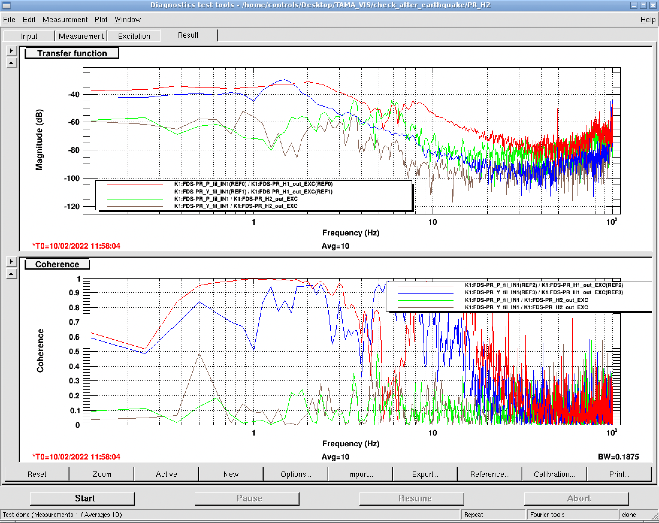
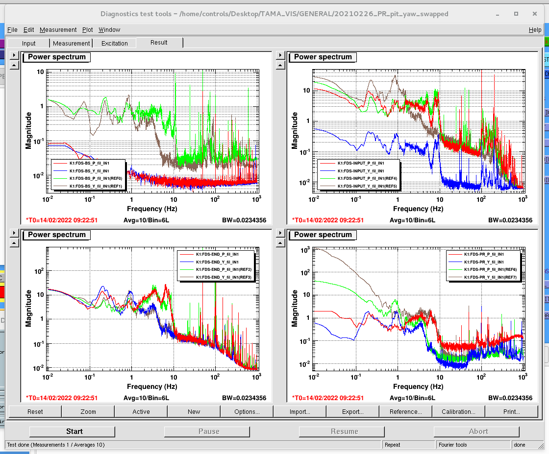
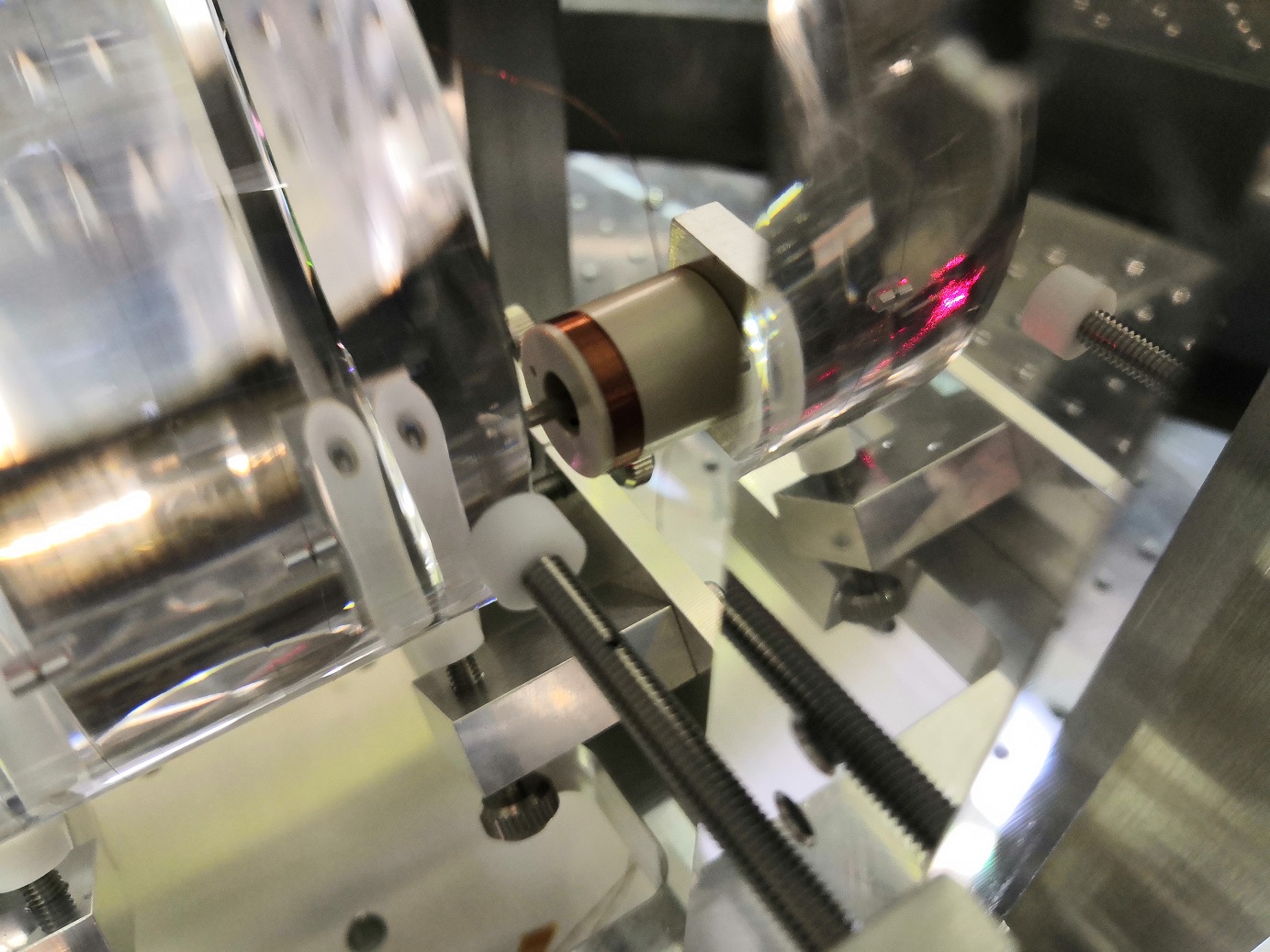
While setting up the magnet health check scripts for all magnets, I did tests for all mirror magnets. And I found PR magnet H2 seems to be fell down. As attached figure, we can see that PR oplev has no response to H2.
Aritomi-san told me that he didn't check PR magnets in the past, which is why he didn't report about PR magnets issue in the past.
But usually we don't use PR coil-magnet actuators. In addition, Aritomi-san has some urgent test to do. So we decide to check PR magnets not now but a bit later.
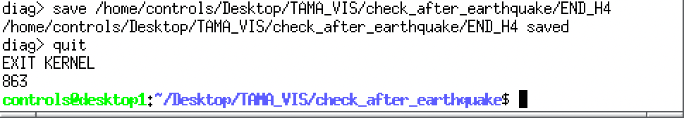
I checked the total time required to check all magnets we have for filter cavity, which is 863 seconds (14.4 minutes)
This check is a count of total time required to run the script. This count is done by writing some lines of codes inside the script. We can see this 863 seconds as attached Fig.1.
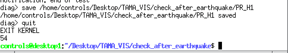
I also checked the time required for checking one magnet, which gives output as Fig.2 (54 seconds). Considering we have 16 magnets to check, the total measurement should be 54*16 = 864 ~ 863 which is consistent with the total time measurement.
Matteo suggests to do such check not only after earthquake, but maybe every month.
[Aritomi, Yuhang]
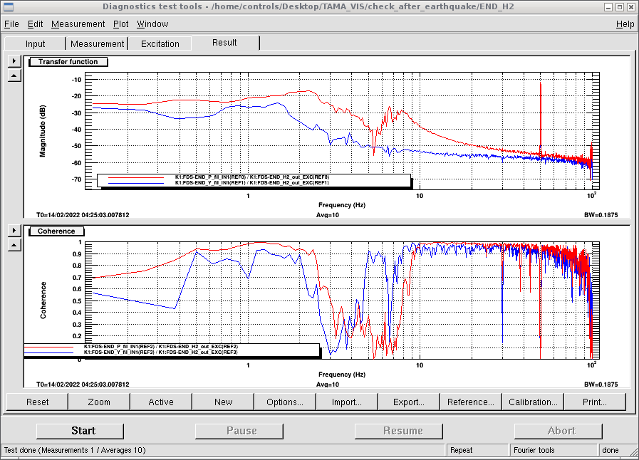
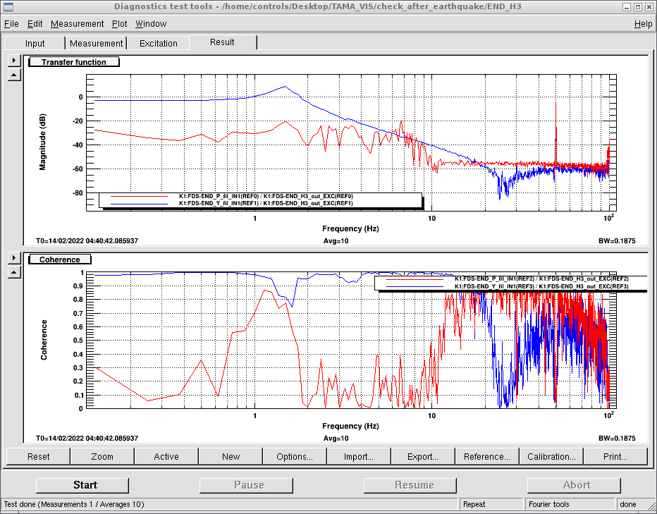
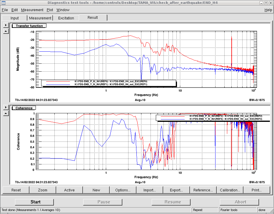
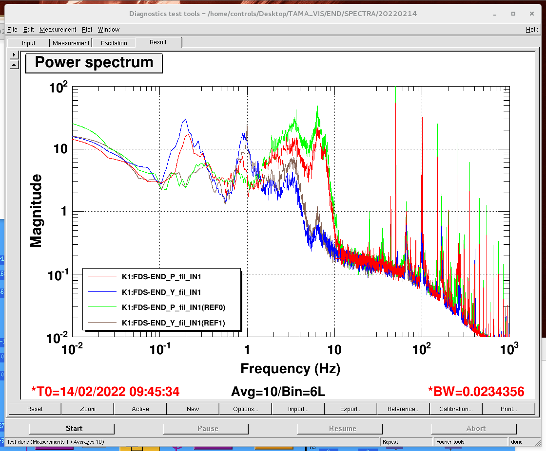
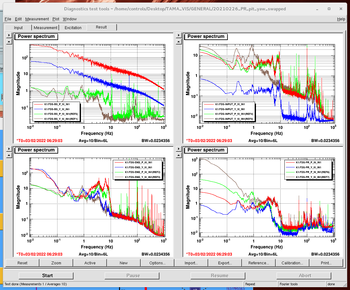
Before the evacuation of END chamber, we checked the END suspension. We excited each coils of end mirror and measured transfer function from the excitation to pitch/yaw oplev spectrum (Fig. 1-4). All coils seem to be working. We also checked END oplev spectra (Fig. 5, 6). The reference in Fig. 5 is one we use for long time, while the reference in Fig. 6 is one measured on 20220128 before we fixed the END magnets. Fig. 6 shows the END oplev spectra become smaller after we fixed the magnets, but Fig. 5 shows that the END oplev spectra are different from the nominal one and still there is a 6.4Hz peak in pitch spectrum.
Anyway, we brought the movable rotary pump from center area to end and started the evacuation. After the pressure in END reaches below 0.1mbar, we switched to the turbo pump. We will open the gate valves between arm/END tomorrow.
The other magnet (left) was released. The TM was released and the chamber was closed.
Ushiba-san(remote), Yuhang
With the help of Ushiba-san, I set up an automatic suspension health check script for TAMA filter cavity.
This work is motivated by the recent discovery of mirror magnets falling down issue. We suspected the coils for BS/input/end mirrors reported in elog2712, 2800, 2812. The earthquake happened on 2021/10/07. Afterwards, we checked oplev spectrum, which helps us to check if there are touching problem. However, we haven't checked whether we have coil falling down. The strange behavior of mirror driving was found much later. Therefore, we conclude that we should check both oplev spectrum and transfer function.
Checking oplev spectrum takes about two minutes. But checking the response of each coil would take one hour, which requires opening diaggui many times and clicking buttons. So we would need to have an automatic measurement of these TFs.
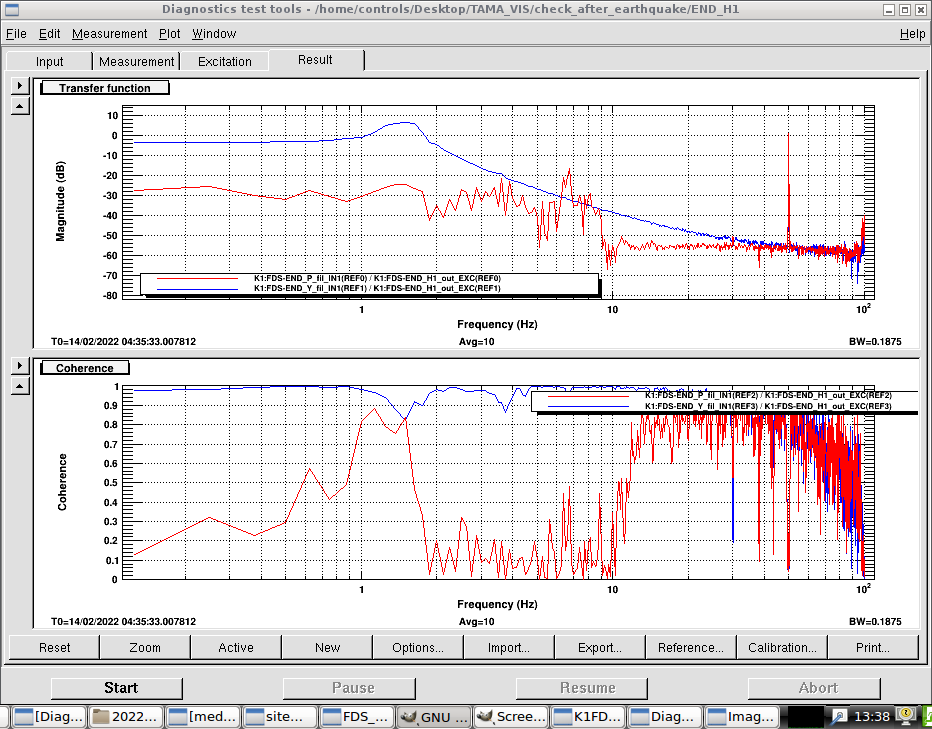
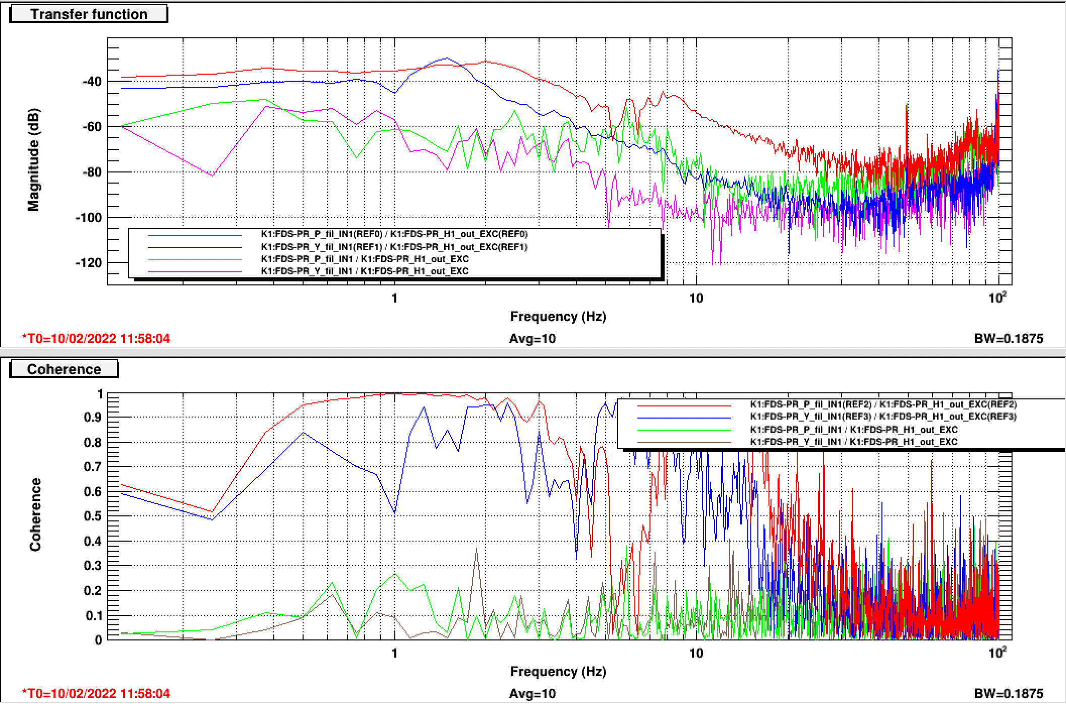
The place of the suspension check shell code is at /home/controls/Desktop/TAMA_VIS/check_after_earthquake. The transfer function is in this directory as well. To confirm if the code I copied works well, I took a measurement of transfer function beforehand as Fig.1. This test is done for PR coil H1. A reference is saved with H1 in function. And a measurement with H1 input signal blocked is in Fig.1 as well, which shows noisy and smaller TF and almost no coherence.
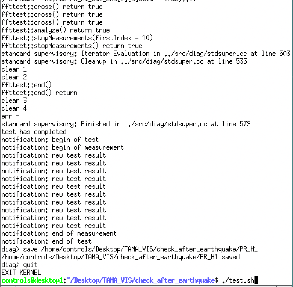
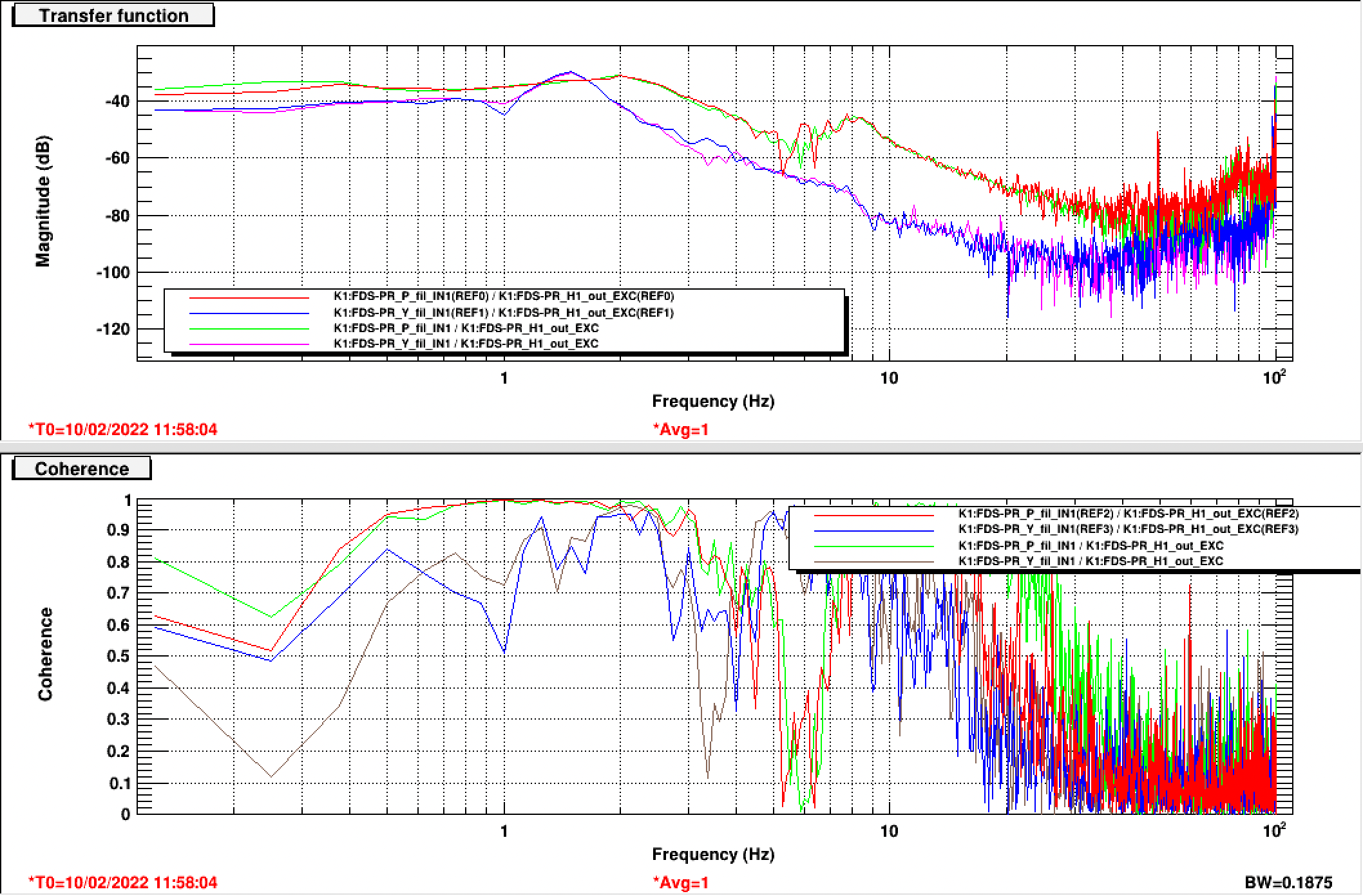
Before taking an automatic measurement, I unblocked signal to H1. Then I cd to the directory where we have the shell code (cd /home/controls/Desktop/TAMA_VIS/check_after_earthquake). Next step is to run ./test.sh . Finally, we can get output at command window as Fig.2. Opening diaggui and checking PR coil H1 TF show a measurement result as Fig.3. We can see it is different from Fig.1, which means that the automatic measurement was really done with H1 signal unblocked. This confirmed that the code I copied is working well.
Next step: create .xml file for other coils and modify shell code accordingly.
Katsuki, Marc
For the measurement with 30 deg input polarization angle we swapped the scan and shift directions (ie in the attached figures 2 nearby points in Y are close in time).
We can now see the stripes in the horizontal direction.
This confirms that the power fluctuations are not correlated to the mirror position.
Yuhang and Michael
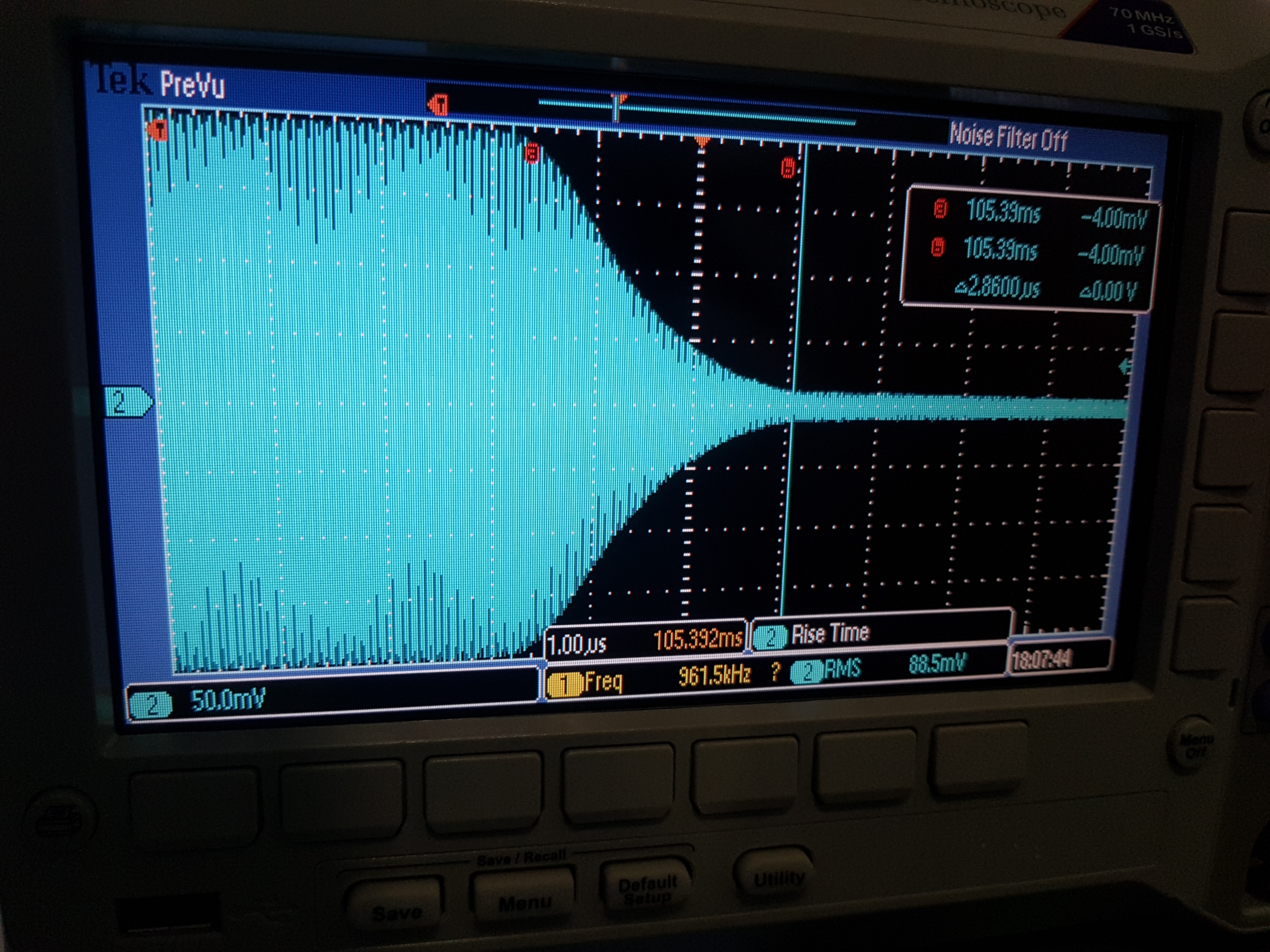
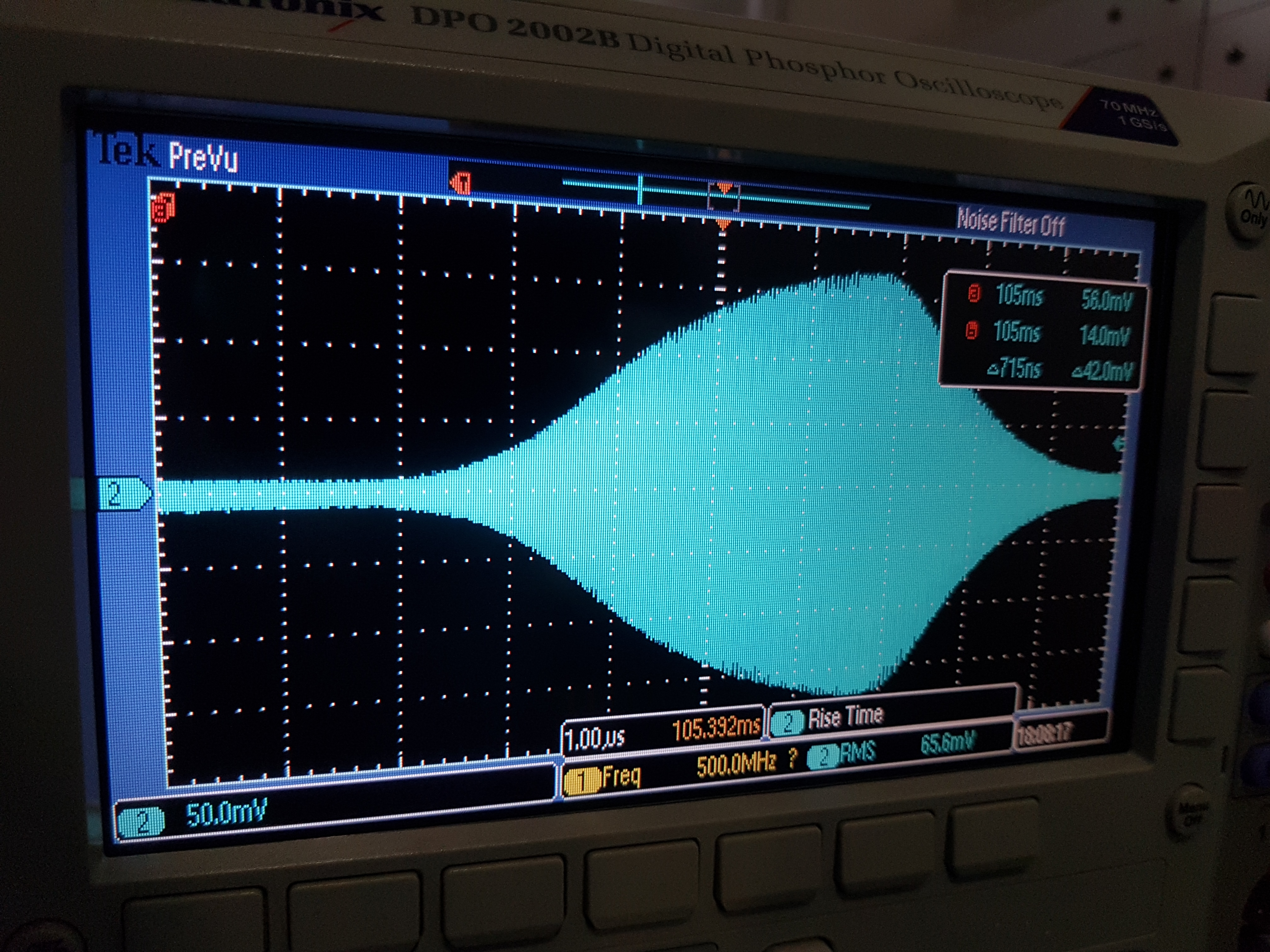
We attempted to obtain a proper ringdown signal of the cavity by switching off the 1st order diffraction passing through the AOM. We used the following methods:
1) Turn off the RF signal from Anritsu function generator to AOM
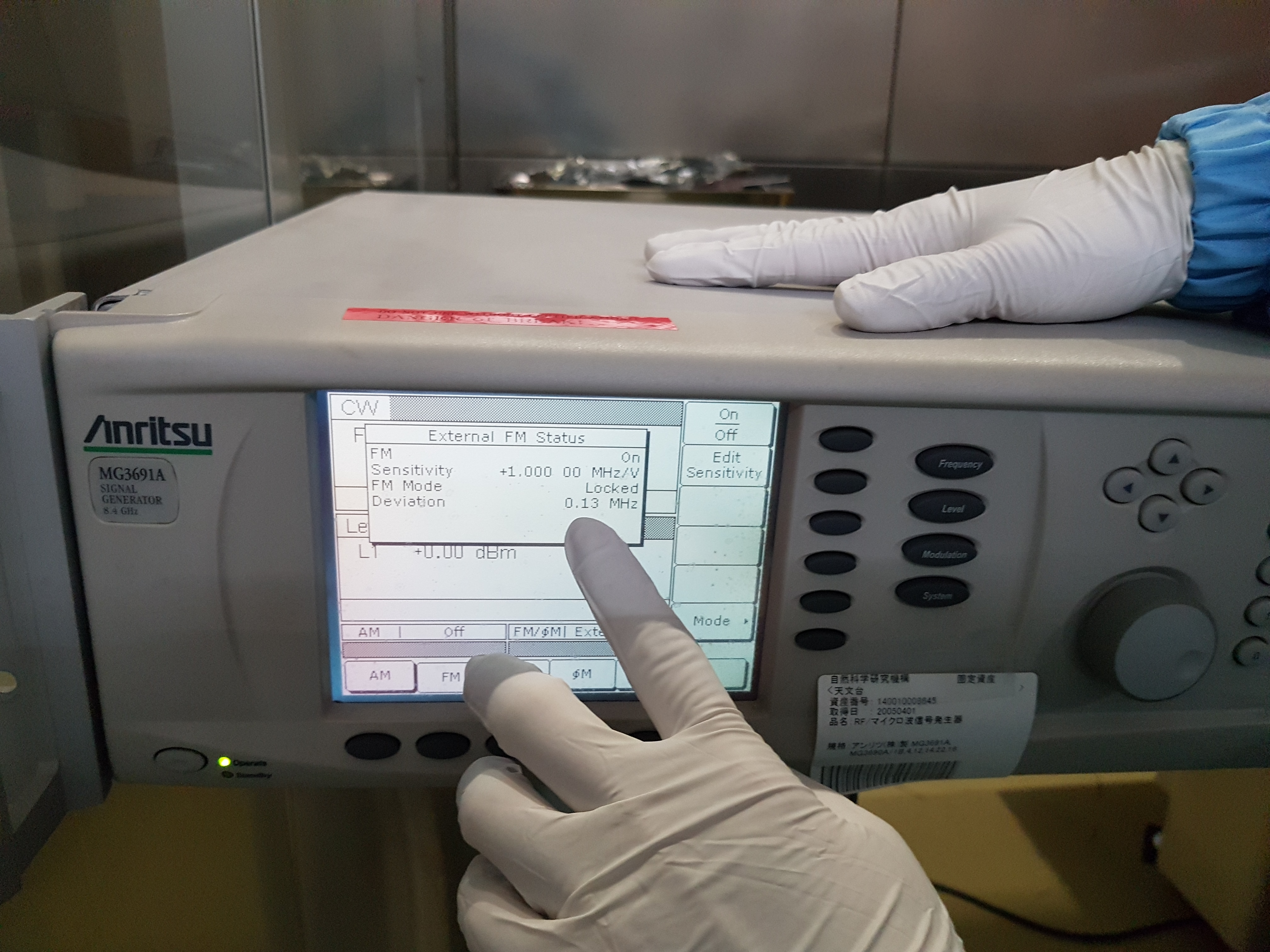
2) Amplitude modulate the RF signal from Anritsu by using Mokulab - a square wave of frequency 1 Hz was input to the Anritsu external modulation port such that the Anritsu signal would oscillate between normal and zero, with an "instant" change (quotation marks).
3) Frequency modulate Anritsu signal, which would then make the AOM efficiency effectively zero. But the Anritsu only allows 1 MHz/V modulation, so it wasn't enough.
These methods produced ring down signals that were nowhere as fast as what was expected - we measured microseconds but are expecting nanoseconds ringdown. So even though the AOM can be turned off more quickly than what we could get by mechanically blocking the beam, we are still limited by the deactivation speed of electronic switches.
One magnet (upper) was glued with the jig and released 3 hours later. The other magnet (left) is under gluing. It will be released on the 14th.
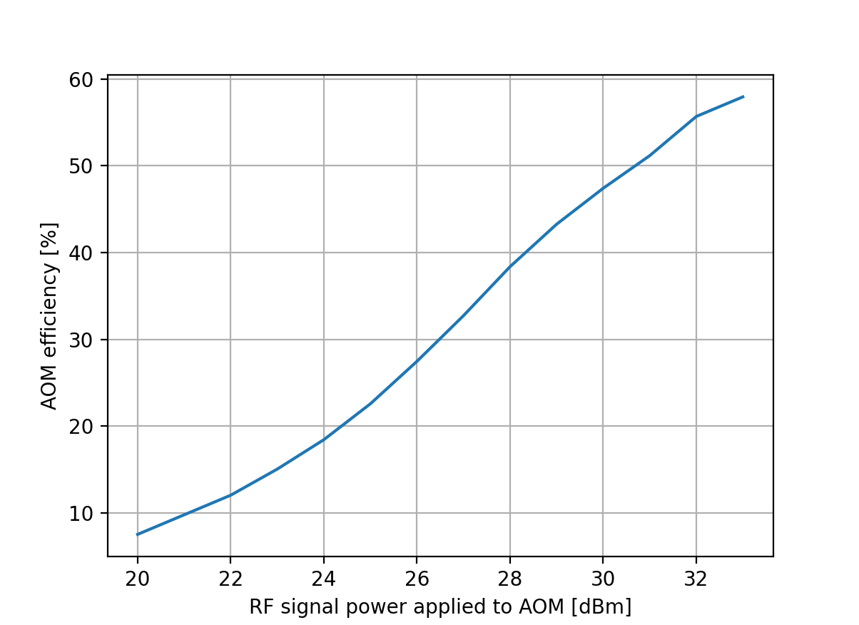
As reported in elog2831, we adjusted AOM incident laser relative angle to AOM and achieved power scattered from 0-order to 1-order of only 6%. We suspected the alignment maybe the main issue since usually 20dBm RF power should be enough. To confirm this, I took the RF amplifier from TAMA ZHL-2, which has bandwidth of 1GHz and can accept incident RF power smaller than 15dBm. I used this RF amplifier to provide even larger RF signal to AOM and check whether we can have larger efficiency.
The ZHL-2 has a gain of 18dB for signal around 100MHz. So I used Anritz to provide 2dBm at the beginning, which passed through ZHL-2 and arrived at AOM. Using power meter (with 55mW incident on AOM), I measured AOM efficiency as a function of AOM applied RF power. The result is shown in Fig.1.
We can see that higher AOM efficiency was achieved by applying higher RF power. In addition, the increase of efficiency with RF power is still quite linear and not reaching flat region. Therefore, it should be confirmed that alignment is not the reason of low AOM efficiency. But a higher AOM efficiency is prevented by not being able to provide a higher RF signal due to device limitation.
Michael and Yuhang
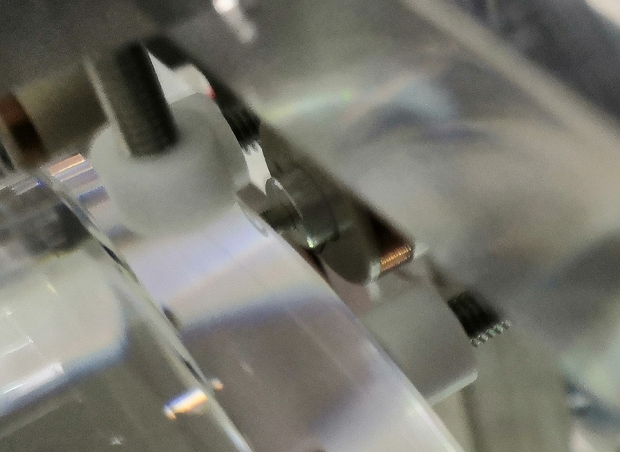
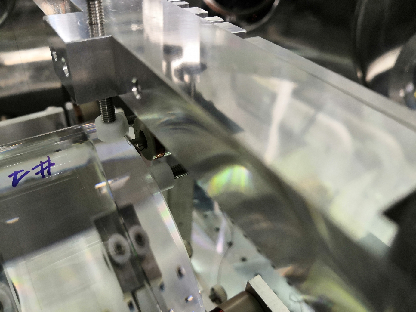
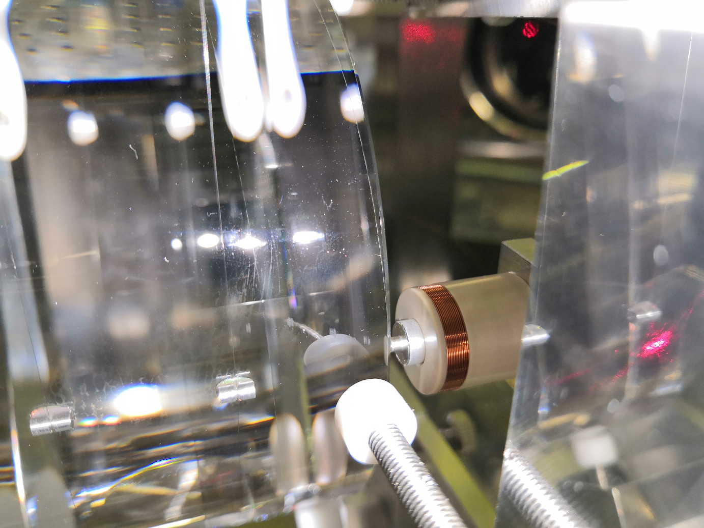
In the past two days, we have been setting up AOM for switching off OPO injection beam fastly. A 'AA.MT110 IR 27' was used to provide the first Brag diffraction. According to specification, about 1 degree (lambda*f/2/v) Brag angle is required. Now, a newport pure rotation stage is used to adjust AOM. Using the current rotation stage, we could achieve efficiency of only 6%. Of course, the RF signal power could provide some limitation considering we can provide up to 20dBm now.
But anyway, we would need to replace it with newport alignment stage 9071 to better align AOM. We would need a high-power RF amplifier for providing higher RF signal level. Since bandwidth of 110MHz is not small, the bandwidth requirement needs to pay attention as well.
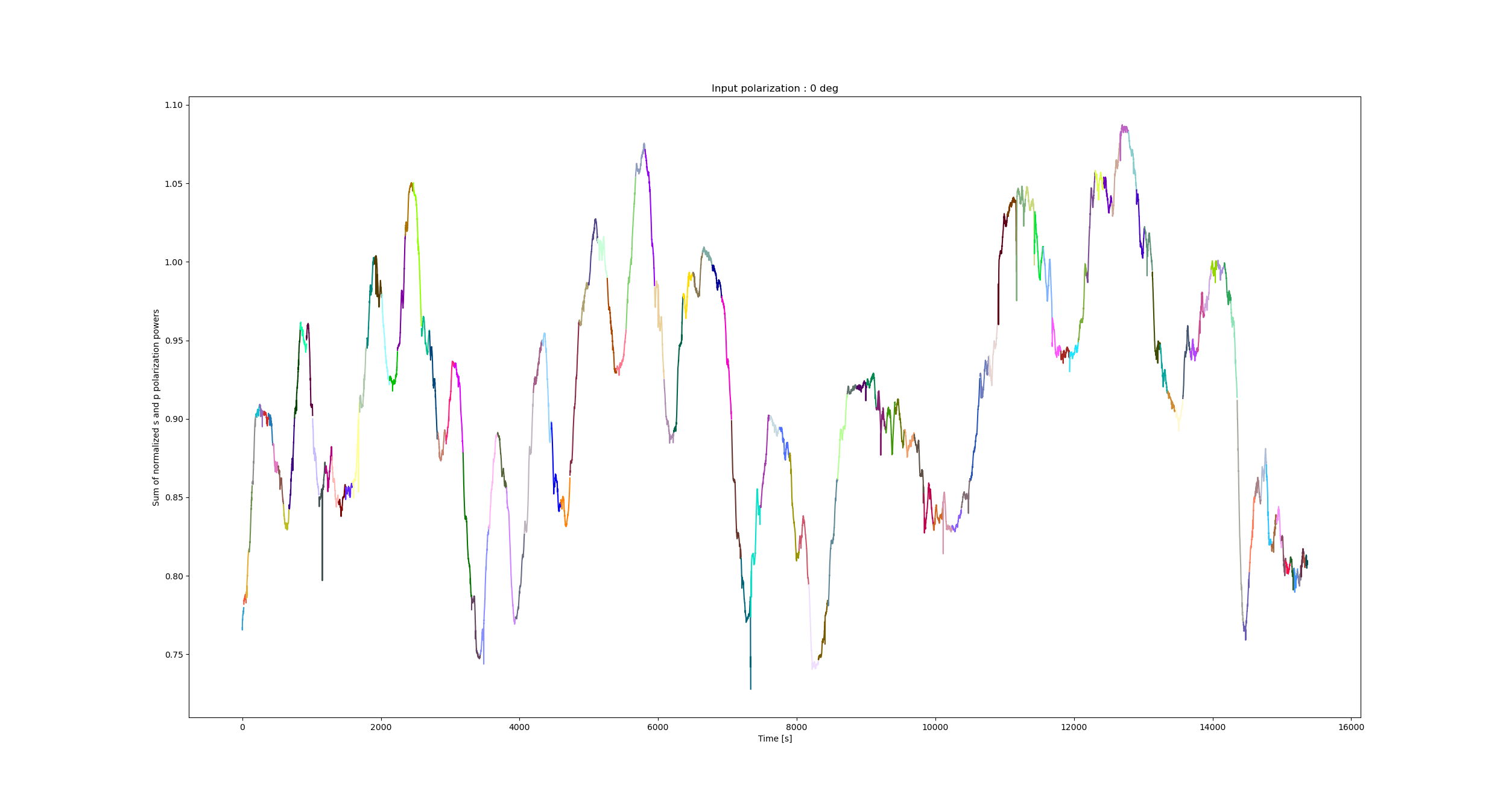
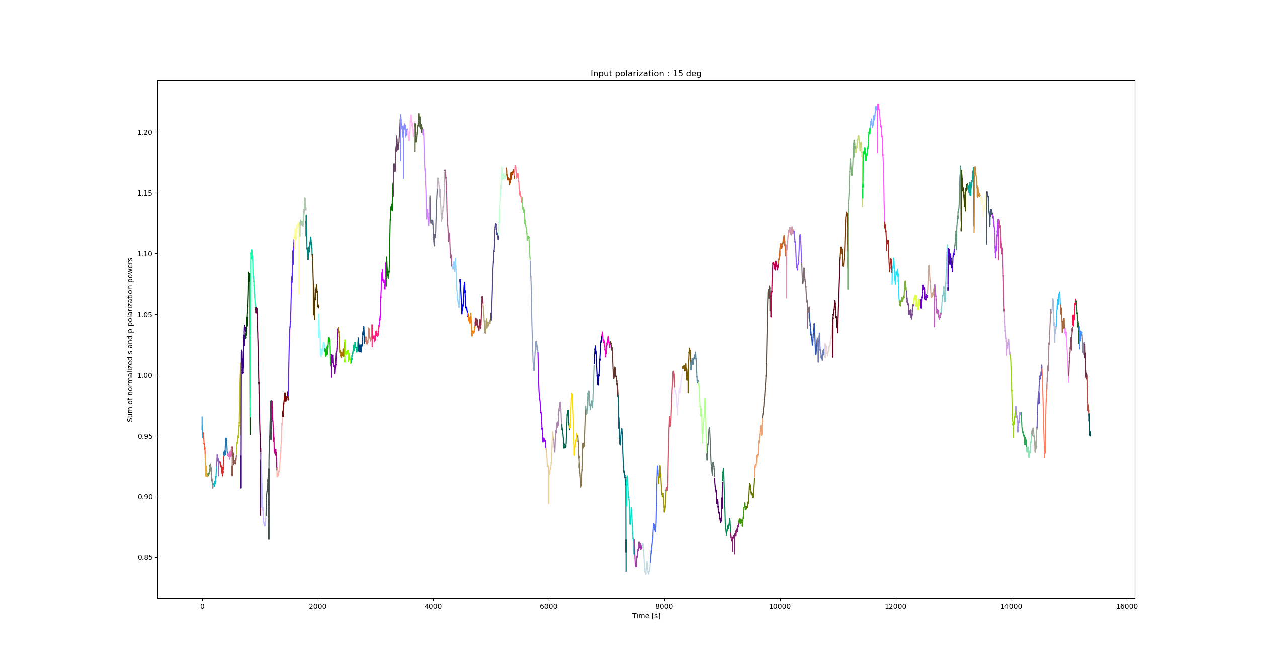
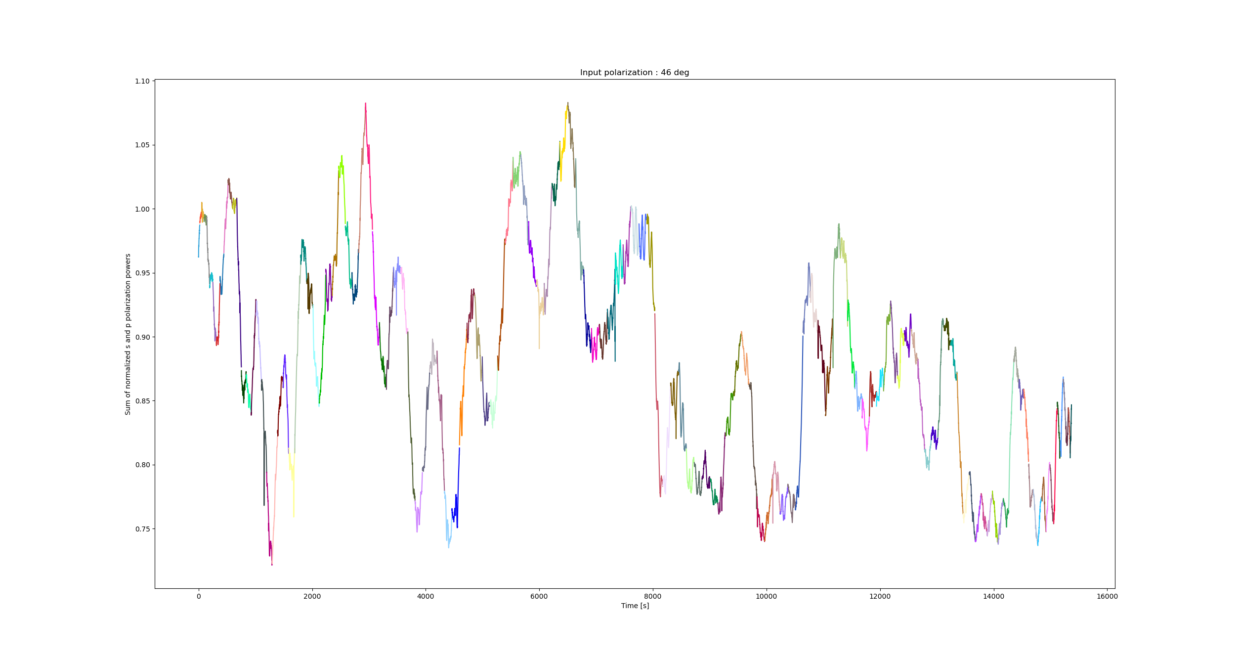
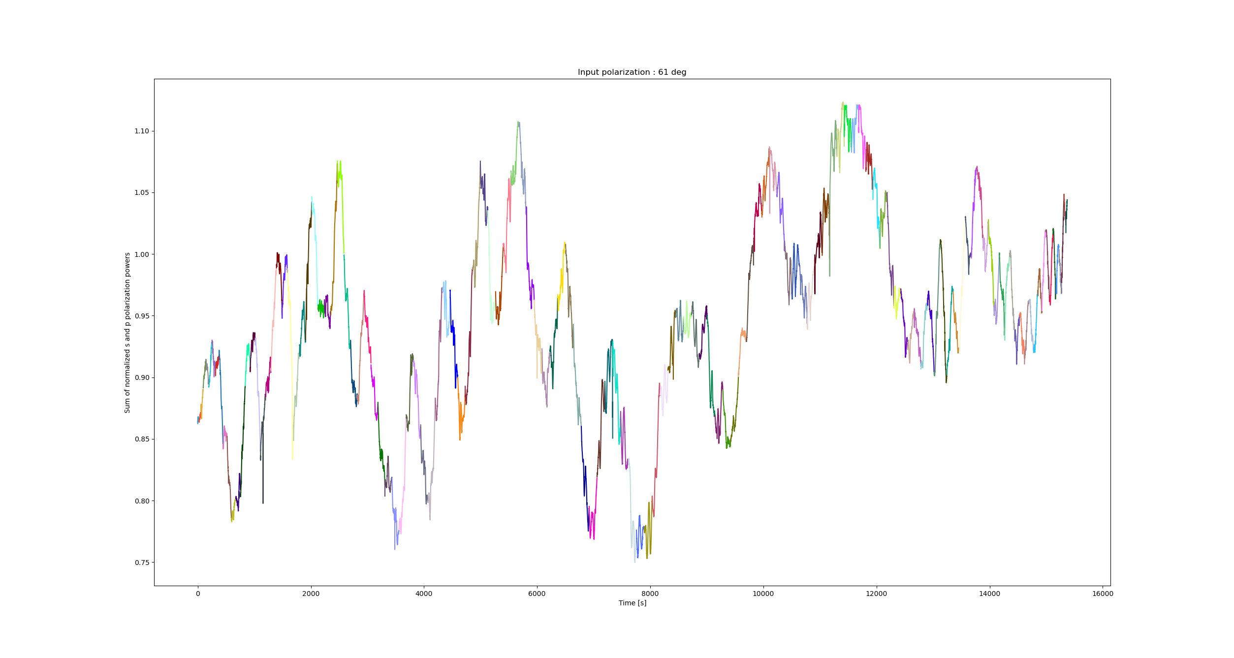
As reported in entry 2817 we can see vertical stripes in our measurements.
One question is are they correlated to the Y (horizontal) position of the mirror.
For reference, the measurement are done in zig-zag ie we scan in X (vertical) and shift in Y.
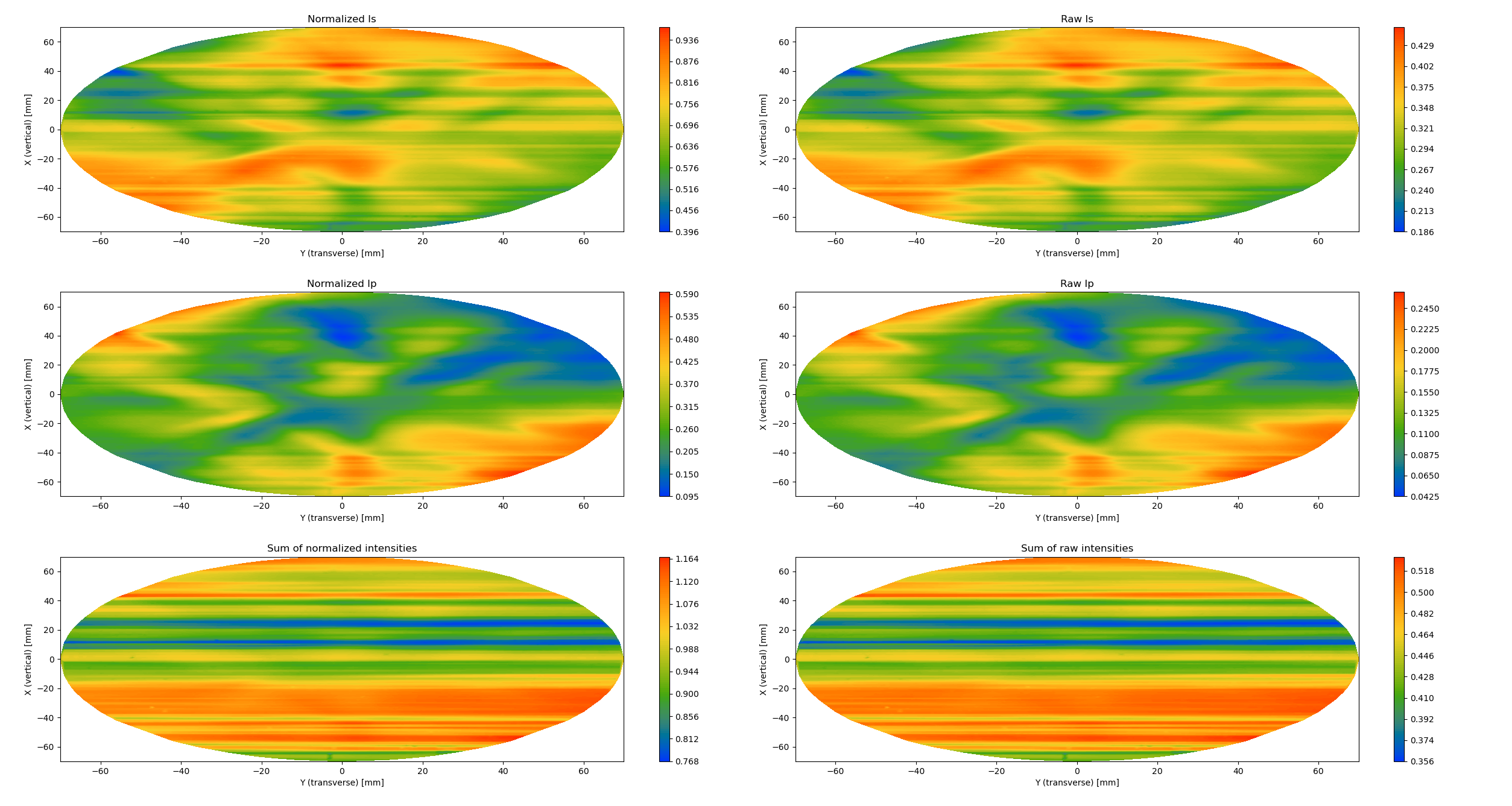
I show in the attached figures the sum of the normalized s and p polarizations for various input polarization angles as a function of time.
The color changes correspond to a change in Y position.
To my eye it seems that these figures show that there is no clear correlations between the Y positions of the mirror and the power fluctuations.
In any case I will try to do further investigations next week.
Katsuki, Marc
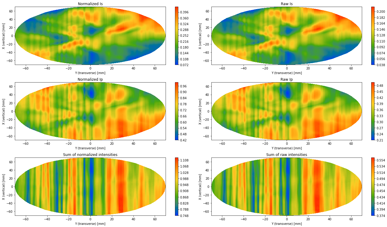
Recently we found out that there are large stripes visibles in the birefringence measurements.
Furthermore, if we check either the raw or normalized s and p polarizations power, their sum is not at all constant (see figure 1).
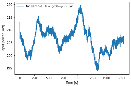
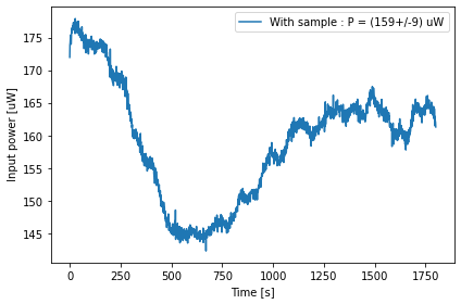
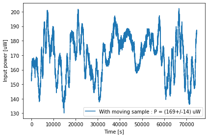
We installed a power meter at the beginning of the imaging unit and measured the pump power without sample (fig2) with sample (fig 3) and with sample moving as a birefringence measurement (fig 4).
The power is not stable at all...
While we could see something like +/- 1 % fluctuations during the polarization calibration, we can see that the long term peak to peak fluctuations seems to be around +/- 10 % during 30min and +/- 20 % during a birefringence measurement.
This explains why we see the stripes and why the sum of s and p polarizations power is not constant during a birefringence measurement.
Note that this large power fluctuations does not affect drastically the birefringence measurements as we don't see the stripes in them.
Furthermore, it seems that these power fluctuations are far more important at low power compared to high power (few watts for absorption measurements) because we can not see the stripes in these measurements.
Another by-product of this measurement is that we could estimate the background level of each PSD to be about 1uV.
After the evacuation of input chamber, I aligned the input oplev by tweaking the steering mirror just after the oplev laser source.
Then I measured the input oplev spectra as shown in the attached figure. The input pitch and yaw oplev spectra look very similar now.
I checked the oplev beam height at the injection, readout viewports. The oplev beam height at the injection, readout viewports were 110mm, 106mm, respectively. I tweaked the injection steering mirror and made the both beam height 110mm, but the pitch and yaw oplev spectra still look very similar.
Before I opened the gate valves between input/BS and input/arm, the pressures in input, BS, arm was 1.3e-6 mbar, 9.9e-10 mbar, 3.1e-8 mbar, respectively.
First I opened the gate valve between input/BS. After 1 hour, the pressures in input and BS chambers became 5.5e-7 mbar and 1.9e-8 mbar, respectively.
Then I opened the small/large gate valves between input/arm. The pressures in input, arm became 5.4e-7 mbar,4.5e-7 mbar, respectively.
Michael and Yuhang
18.2% power is not coupled.
Michael and Yuhang
We checked the mode matching condition between BAB and OPO. 13.2% power is not coupled.