NAOJ GW Elog Logbook 3.2

Recently I've been trying to compute birefringence from TWE measurements of spare ETMY based on Aso-san's computation.
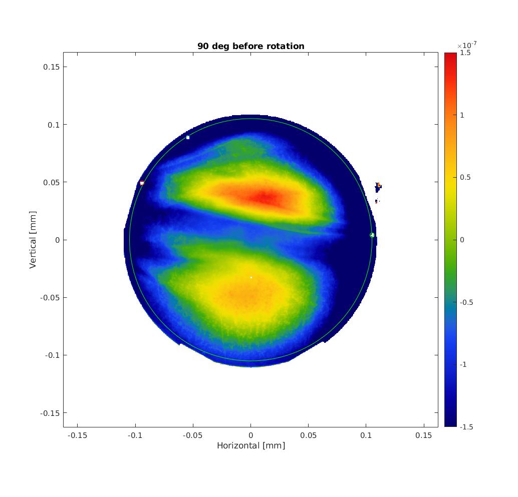
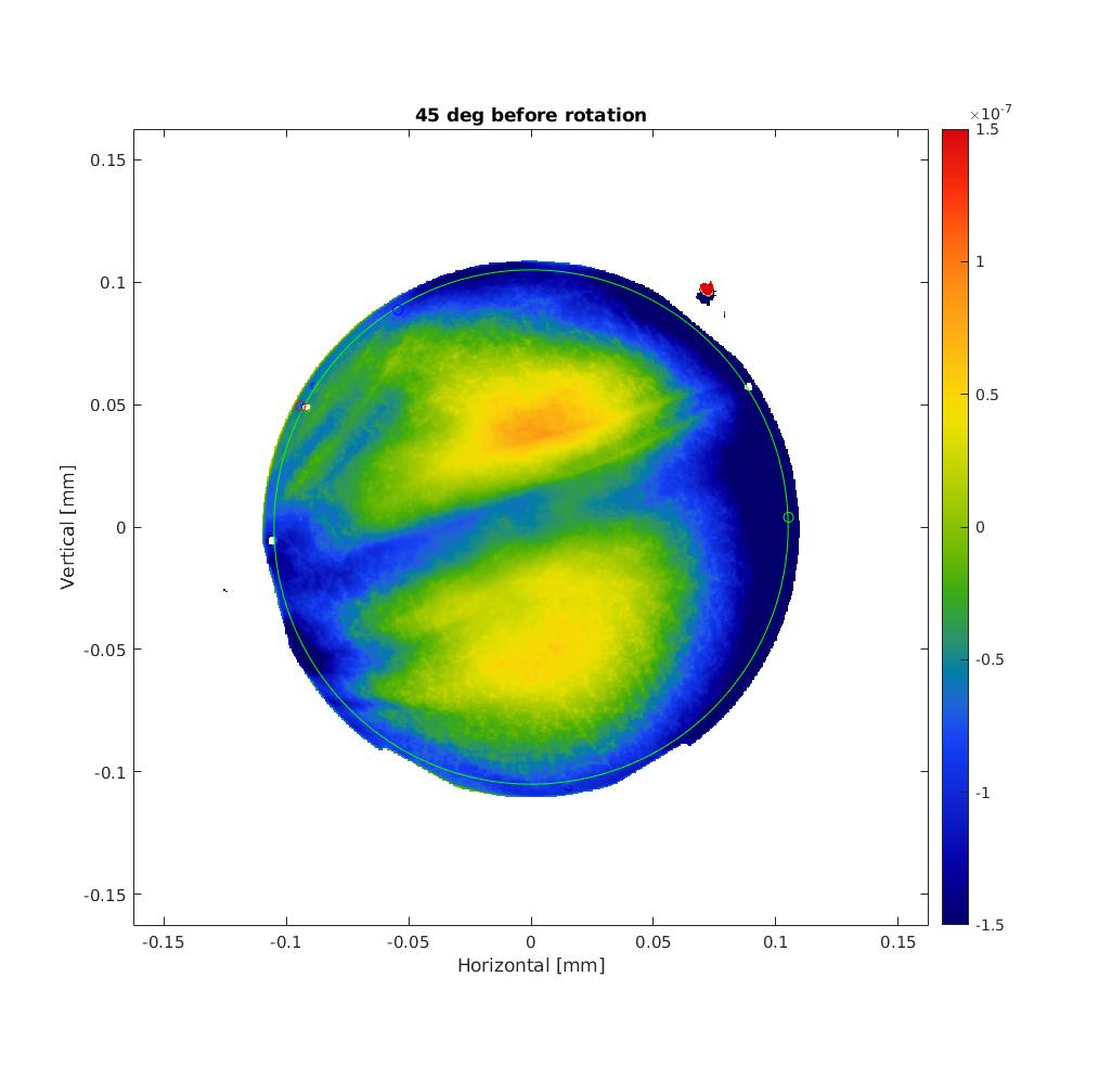
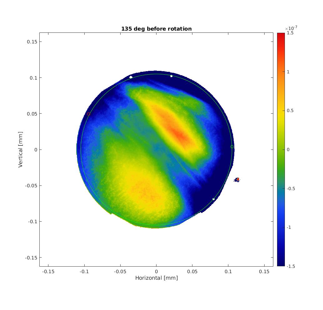
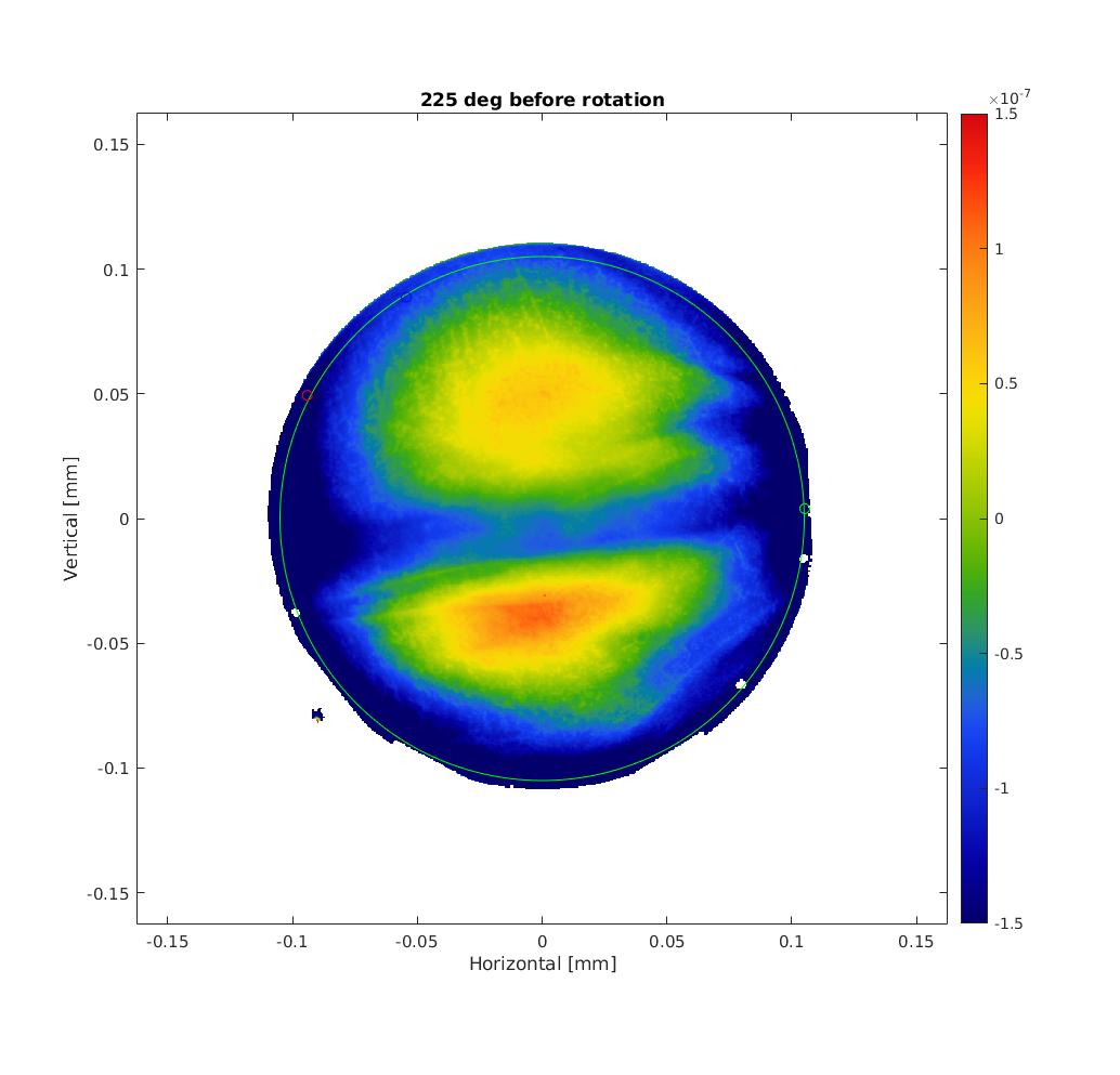
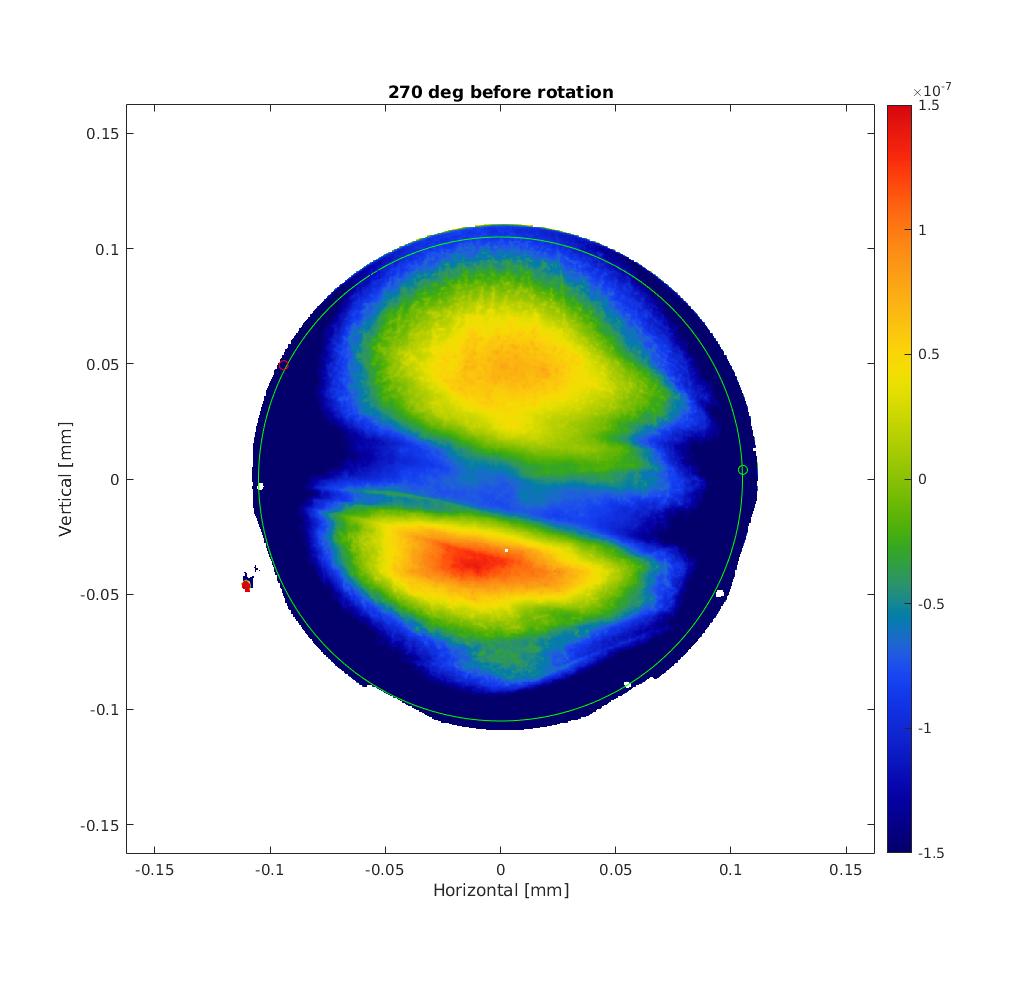
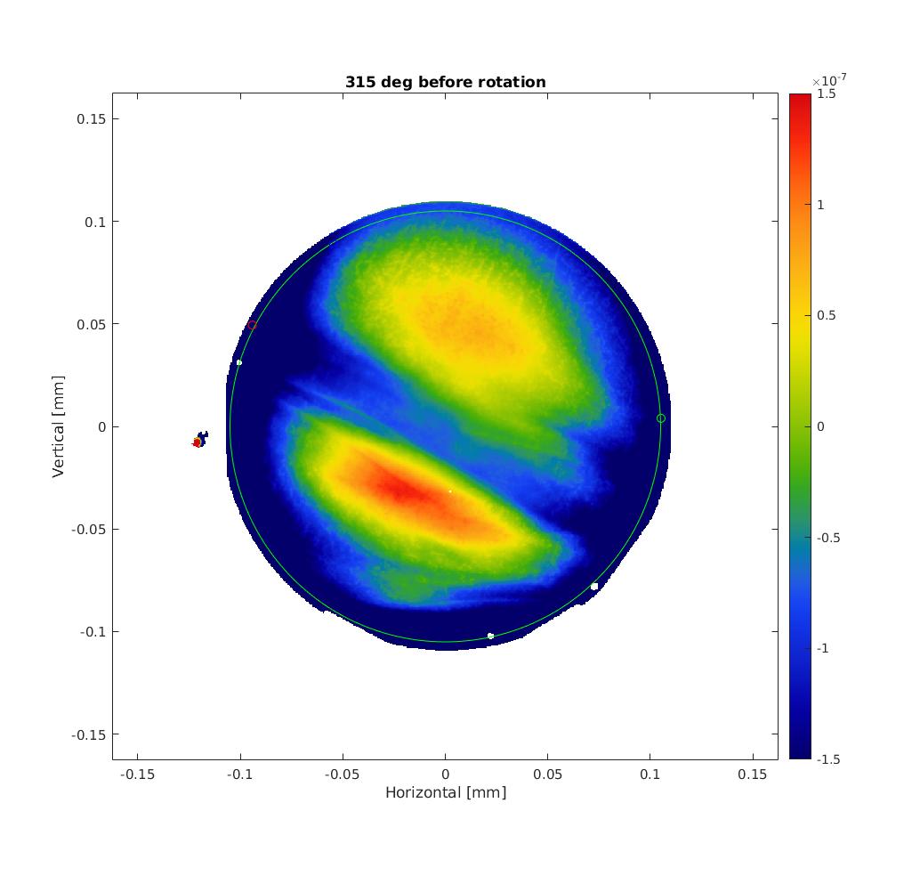
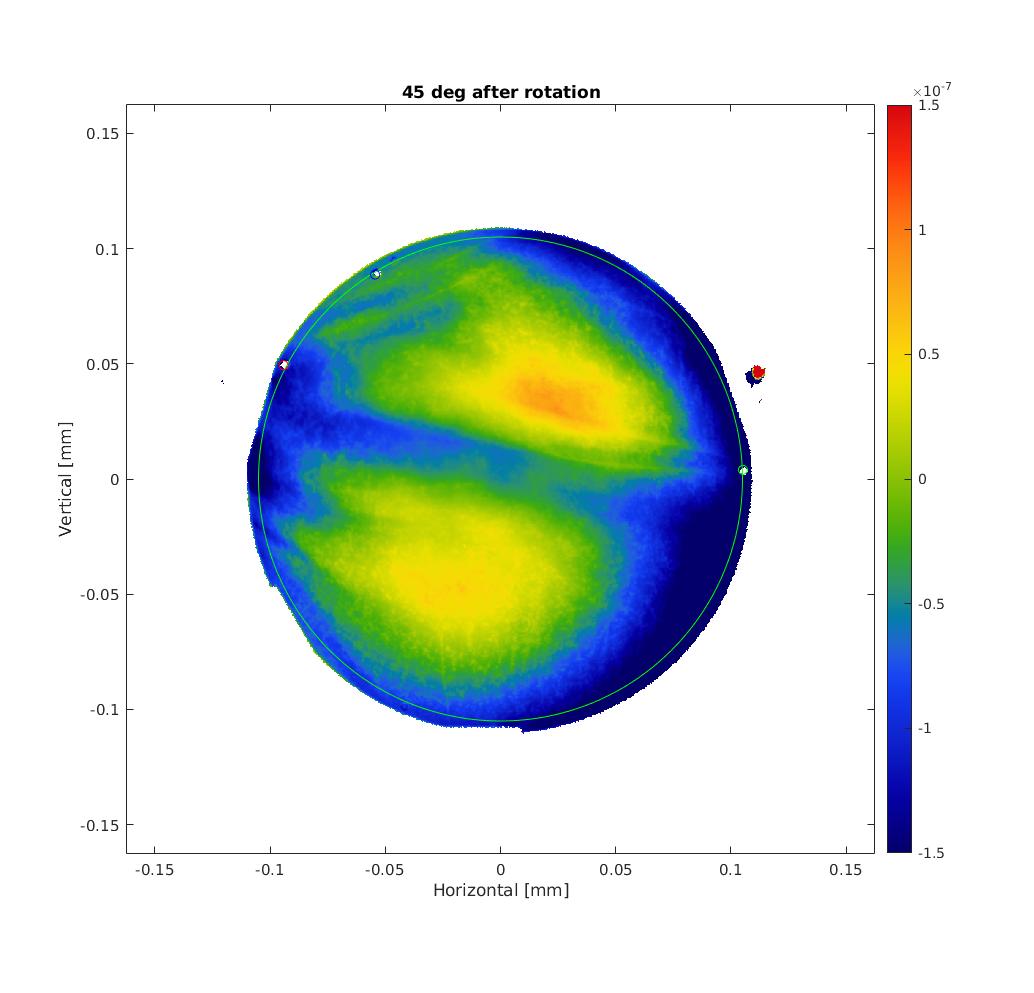
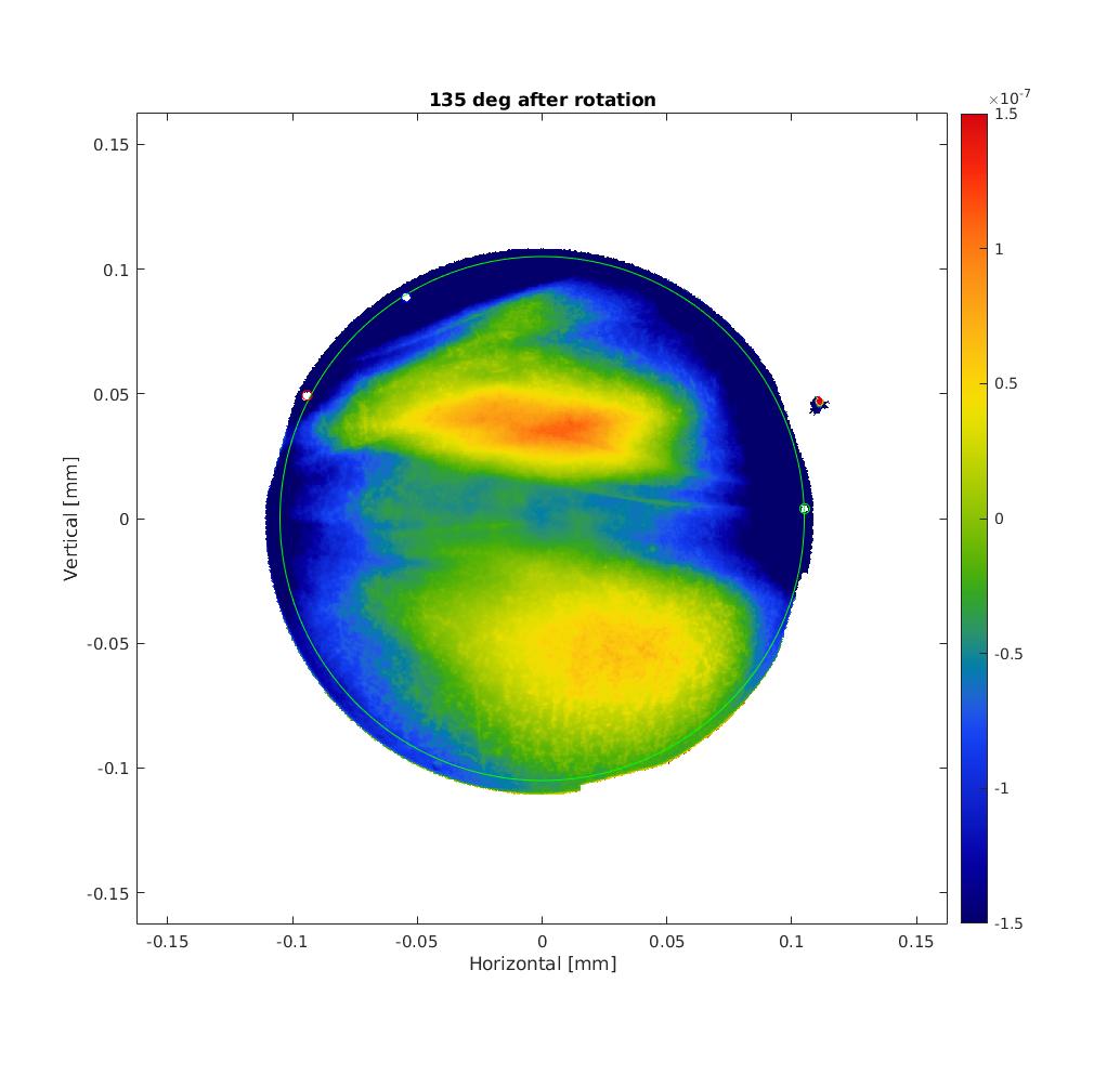
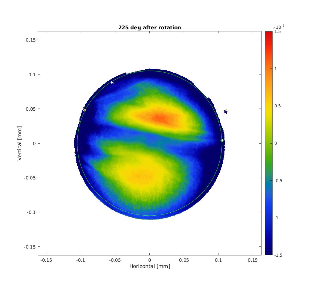
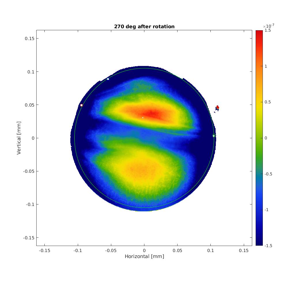
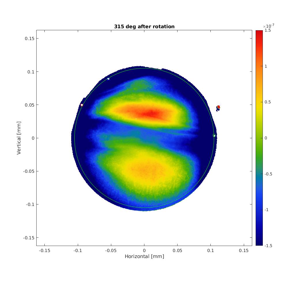
I'm using the S1thruS2 measurements with roll angle of the mirror of 45, 90, 135, 225, 270 and 315 deg with 20 measurements averaged.
The code I wrote does the following :
1) Find the real center and roll angle of each TWE maps
Hirose-san who did the TWE measurements at Caltech placed 3 markers on the mirrors.
First I overlapped 3 circles on the markers of the map with roll angle of 90 deg as it is the same orientation as the PCI measurement.
Then, I changed the centering of all other maps + rotated them to match the circles positions of the 90 deg one.
See figures 1 to 6 for the TWE maps (piston, tilt and curvature removed) without rotation and 7 to 11 for the rotated maps.
2) Sanity check of the RoC
OSCAR is used to removed the piston, tilt and focus of the TWE measurements but states that the removed RoC is about -716 m..
This is actually due to the Fizeau interferometer setup. Computing the RoC taking into account the clear aperature and position of the reference sphere gives a mean RoC = 1.9 km (as expected).
Especially, we recovered the same RoC as measured by Hirose-san with 270 deg roll angle.
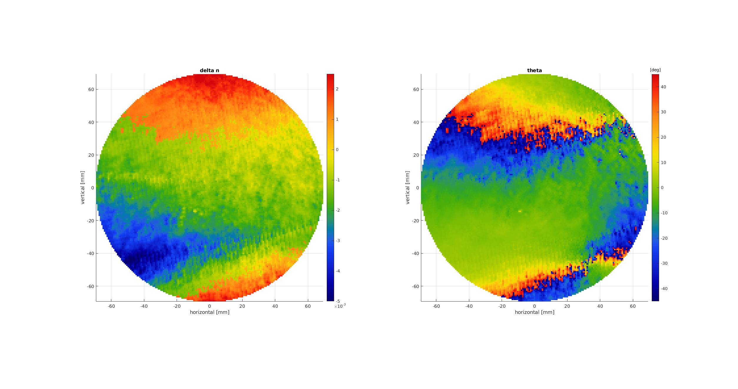
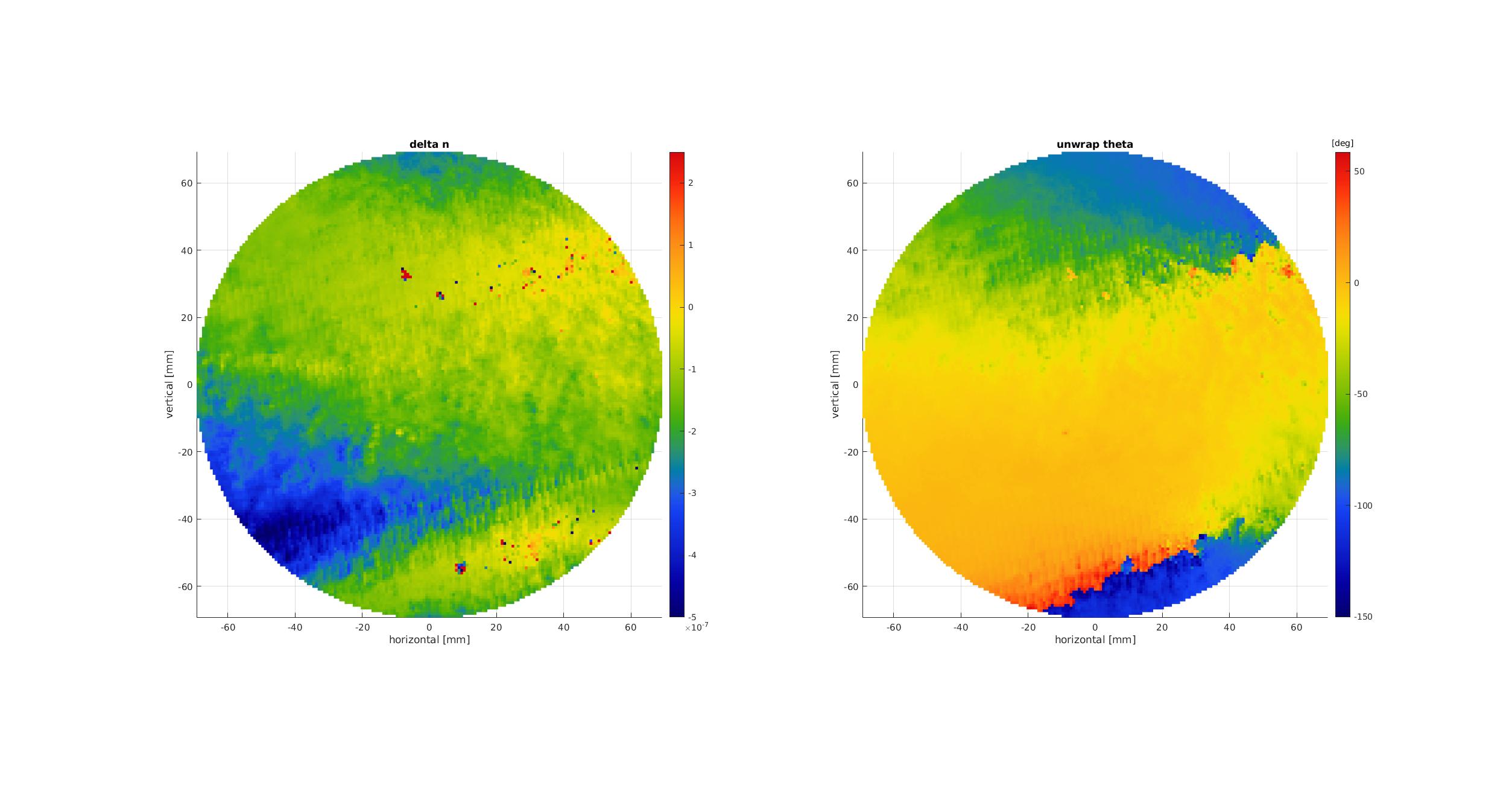
3) Combining TWE maps into birefringence
Using 4 rotated maps, it is then possible to compute the spare ETMY birefringence (delta n and theta the fast axis orientation) as in figure 12.
Actually, because there is an arctan(2*theta) used, theta is only defined between -pi/4 and pi/4 that causes some wrapping of theta (and therefore delta n as well).
So in figure 13 I used an unwrapping algorithm to try to remove this wrapping. Results are reported in figure 13.
We can recognize so similar patterns to the measurements with the PCI setup. Final conclusion should be done after a new direct measurement with the beam at normal incidence).
4) Next steps
- Tune the unwrapping algorithm -> still some issue at the bottom of the map
- Check the orientation of the mirror during PCI and TWE measurements to understand why there seems to be both a vertical and horizontal flip with respect to each other
- Finalize the direct measurement at normal incidence
For easier comparison with direct measurement with PCI (see elog 2755), I show here the absolute value of delta n flipped both horizontally and vertically .
It seems that the larger delta n area have somehow a close triangular shape.