NAOJ GW Elog Logbook 3.2

L1: 37 cm
L2: 46 cm
L3: 55 cm
the final beam waist is 52.7 micrometer and the position is at 82.2 cm.
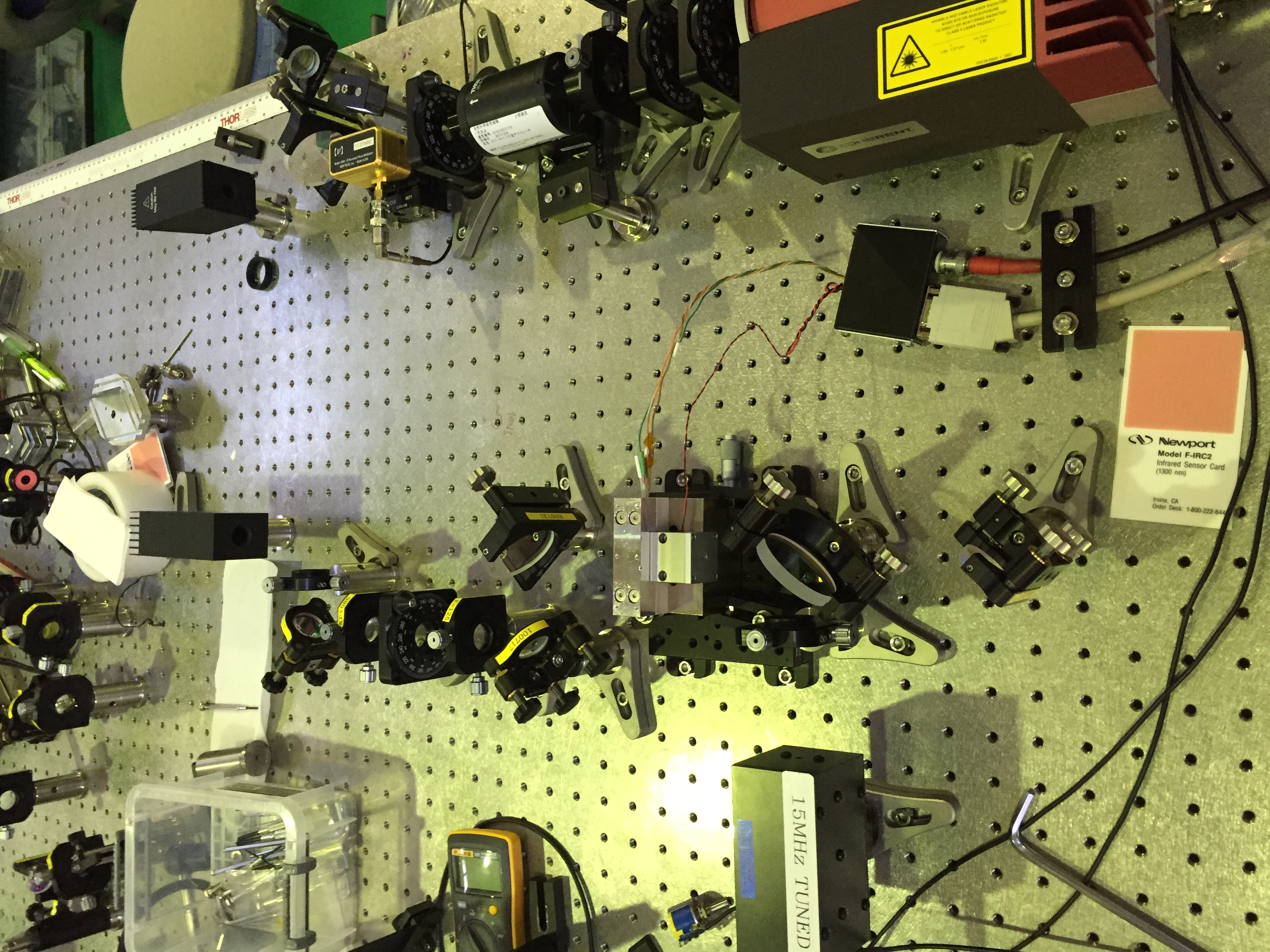
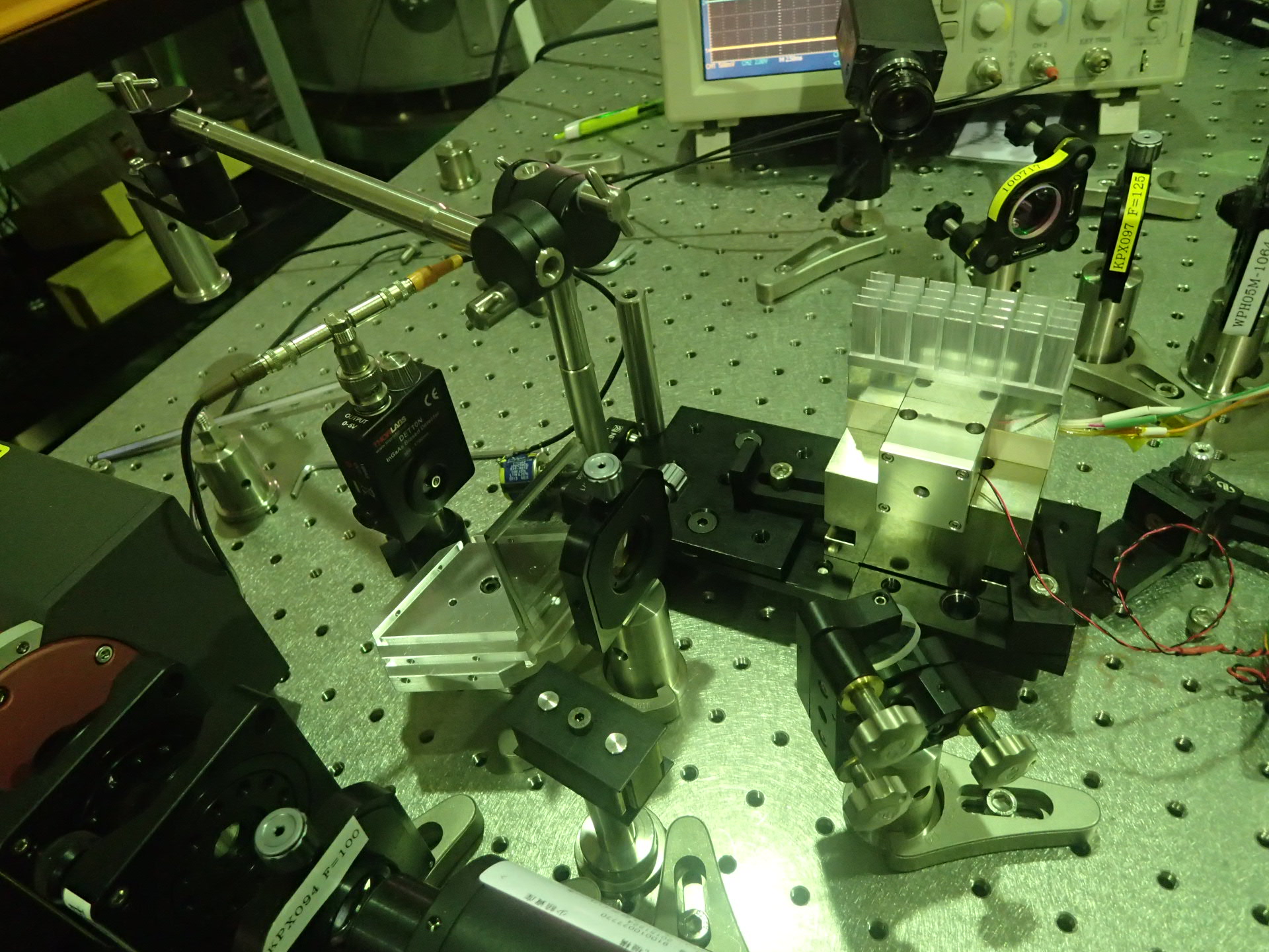
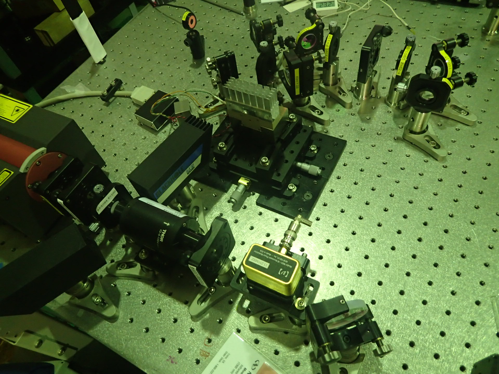
The first picture shows what we have on the optical bench before holiday, it is only for doing the measurement, so the dichroic mirror is not in the right gesture. So today I flipped the dichroic mirror, and put the SHG housing in the right position and direction, according to the result showed in the last paragraph. Aligned the inject beam and the reflection beam, got the transmission beam after the SHG and the reflection beam at the back side of the mirror after EOM. I tried to find some mode but did not get any. I will try to do it tomorrow.
Another problem is that I thought the stage we are using now is broken...in one of the direction, it can only move one way, but it can still be used.
This week we increased the height of the crystal instead of lower the miniscope. But after the increase, we still cannot get rid of the higher modes. We guessed it is because of the mismatch of the beam waist size. Since the increase of the crystal was reached with putting a spacer under the 'L' part which used to fix the crystal, the wire of the thermal sensor and the peltier are also connected to this part, we cannot push too much on the crystal,so now when we touch the wire outside the housing, the position of the crystal will change slightly. Another problem is that we found out the first turning mirror is too closed to the beam waist focused by the first lens of the telescope, and this caused the optical damage of the mirror coating, since the power density at the beam waist is too high when we use the full power of the laser. So we decided to move the the easily damaged turning mirror one hole closed the first lens, and do the same change with all the other component of the telescope without changing the distance between them. Then according to the new version optical scheme, we changed the dichroic mirror into the one transmit green and reflect red. In this case, we can use this dichroic mirror and the last mirror of the telescope to adjust the beam, things became easier. As I mentioned before, we guess the reason of the higher mode existence is because of the mismatch of the beam size. So we turned the cavity again,inject the beam from the back side of the housing, tried to lock the cavity and get the exact beam waist size we need. Give the EOM 15.235MHz modulation and use the PD to get the error signal. With the demodulation board found in TAMA, and the Stanford as a low pass filter, we locked the cavity, but cannot get rid of the offset. The lock last for more than two hours until we swtiched off everything and left. During the lock, we measure the beam size and got the beam waist size the cavity need is 54.1 micrometer. So the next step is the adjust the telescope again to get the beam waist size given by this locking.
Picomotors of the 4 suspended mirrors (2 of filter cavity and 2 of telescope) need to be put in operation.
The cables that connect the picomotor to the the chamber flange inside the chamber should be already in place for the 4 suspension (to be checked)
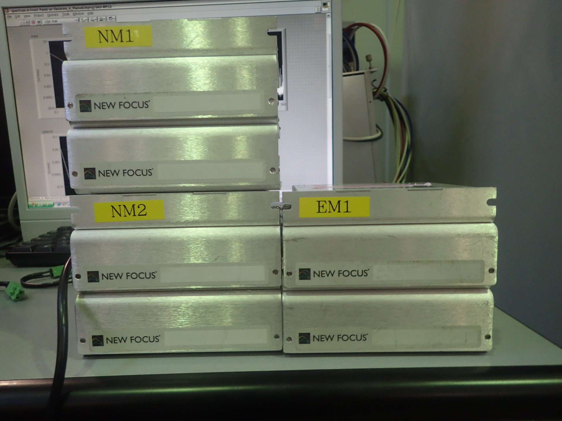
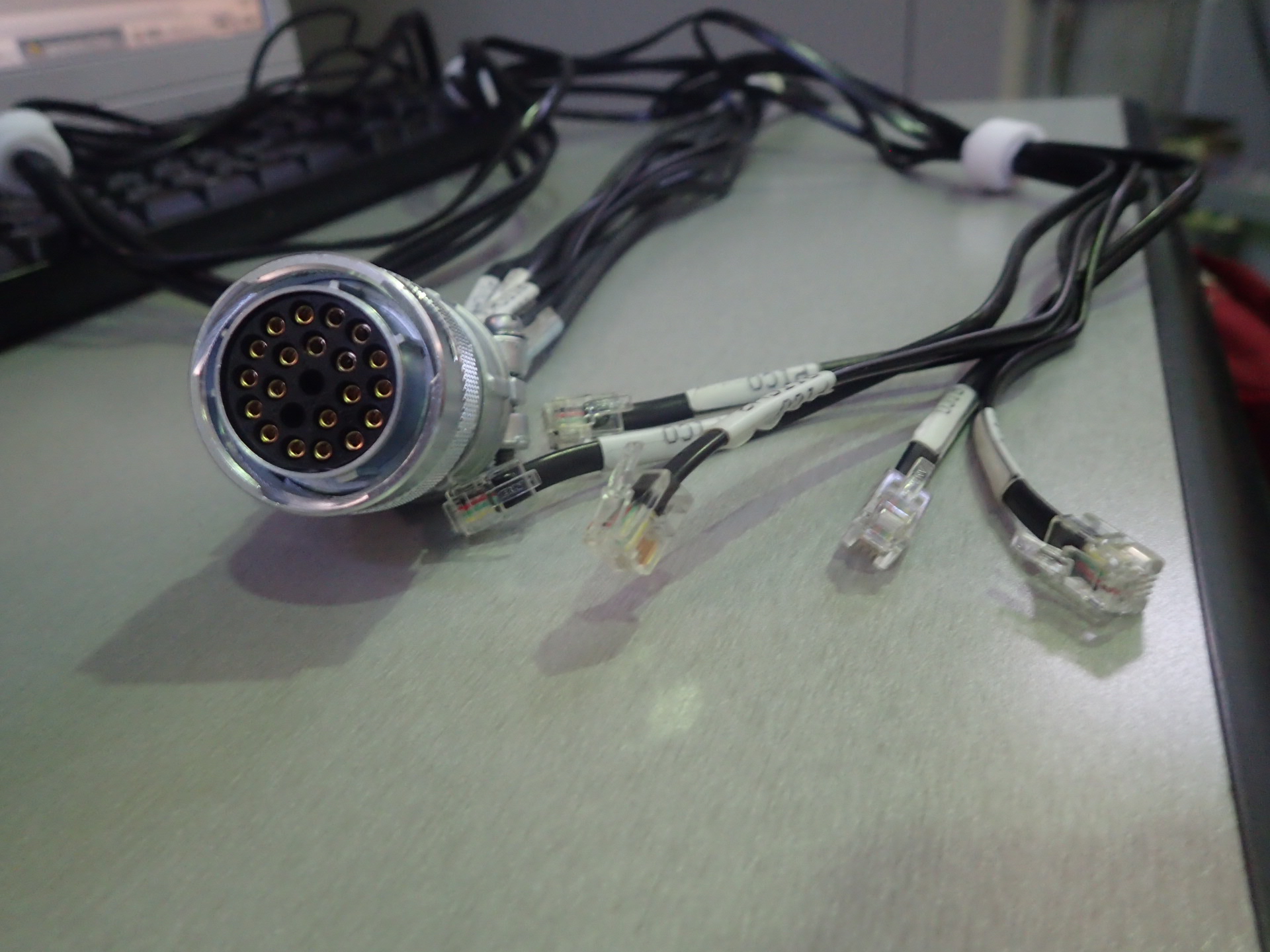
Takahashi-san provided driver for the picomotor (fig 1) to be connected to a cable (fig 2) to the extern part of the flange. This device were used to control picomotors of TAMA SAS.
The drivers can be controlled by a joystick and by remote using a labview software that Takahashi-san will provide
Some more information:
1- Picomotors drivers are 3 (IM1 IM2 NM3), NM2 could not be found. We checked in both end rooms without success.
2- We need 4 cable to connect them too the 4 chambers. For the moment we have only 2. (Again we checked in both the end rooms). According to Takahashi-san the missing two cable can be built using spare connectors like that in figure 2 and spare suitable cables I already found in TAMA. Takahashi-San can also provide the suitable tool to connect pins in the connector.
3- All this material is temporarily stored in a box under my desk in TAMA
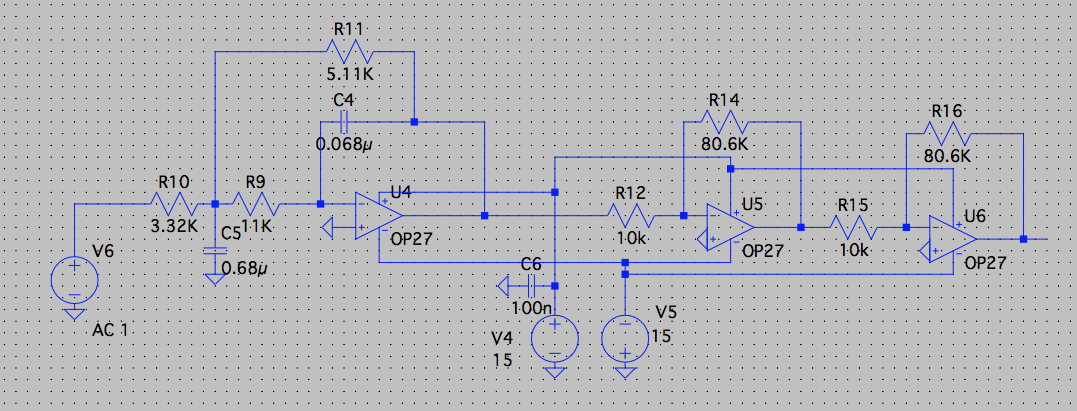
In the past days with the valuable help of Matteo L. we realised 4 NIM-modules able to filter an input signal with a lowpass filter of 2 order (cut frequency at 100 Hz) and to amplify it of a factor 100.
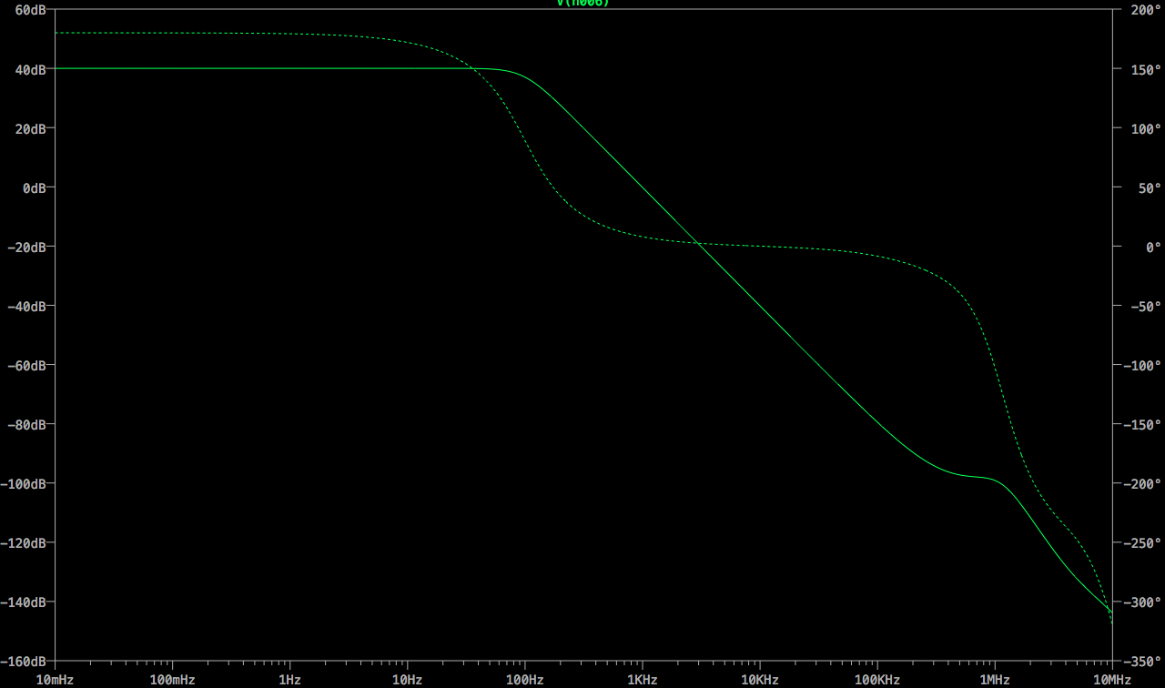
The scheme of the circuit, using a multiple feedback (MFB) filter, drawn with the software LTSpace is shown picture 1 and its transfer function in picture 2.
Each module can process two channels, so in total we have 8 available filters+amplifiers.
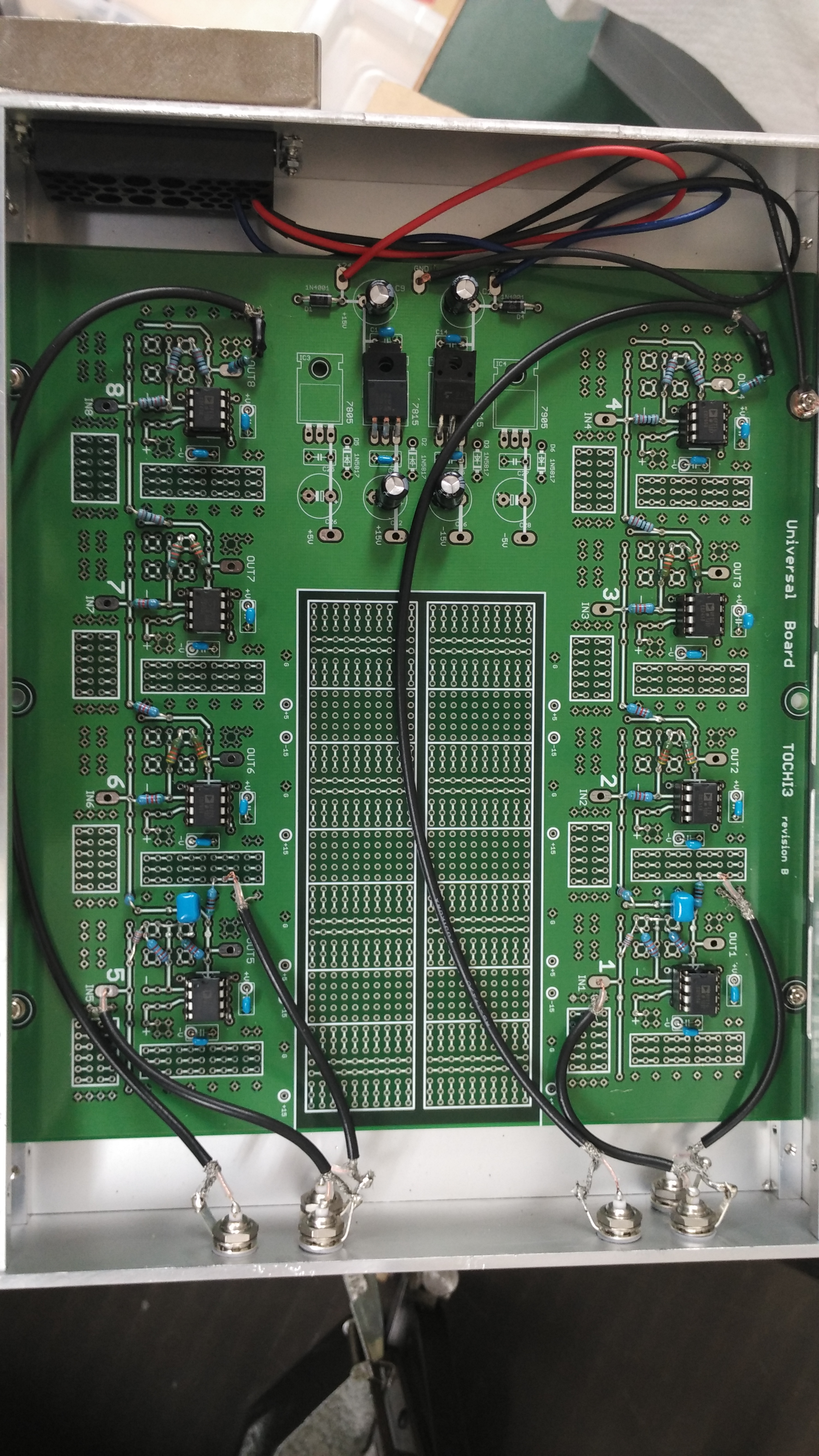
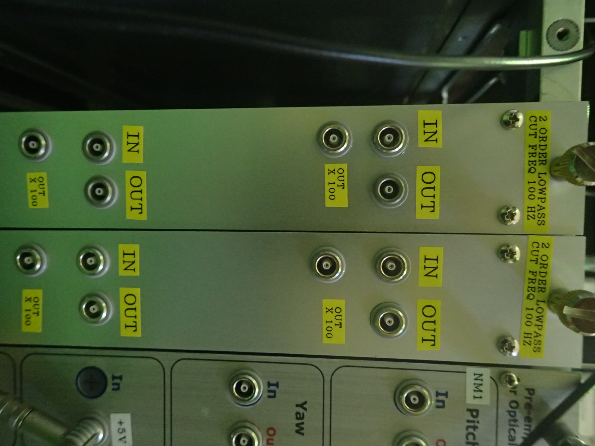
A picture of the circuits and the module are shown in attached files 3 and 4.
They will be used to filter and amplify the output signal of the PSD used for the filter cavity optical levers, replacing the stanfords that have been doing this job up to now.
Today we restart the alignment from the first beginning. Firstly, with the power meter, measure the input and output of the EOM, adjust the transfer stage until almost the same power value. Then for the component, try to adjust them until the beam shine on the middle of everyone. With the tilt angle of the mirror, adjust the beam height as 76cm at both the near field and far field. Finally, we found out the transfer stage under the SHG housing is too high for present beam height.So we remove the bottom layer, got the transfer beam and the reflection beam, but the green is weak. The possible reason may be:1.Low input power 2.During the adjust process, the position of the lens may change,leading to the change of the waist position, so the input beam size of SHG crystal is too large 3.The polarization 4. The misalignment of the beam height and the crystal height. We will check all the possible reason tomorrow.
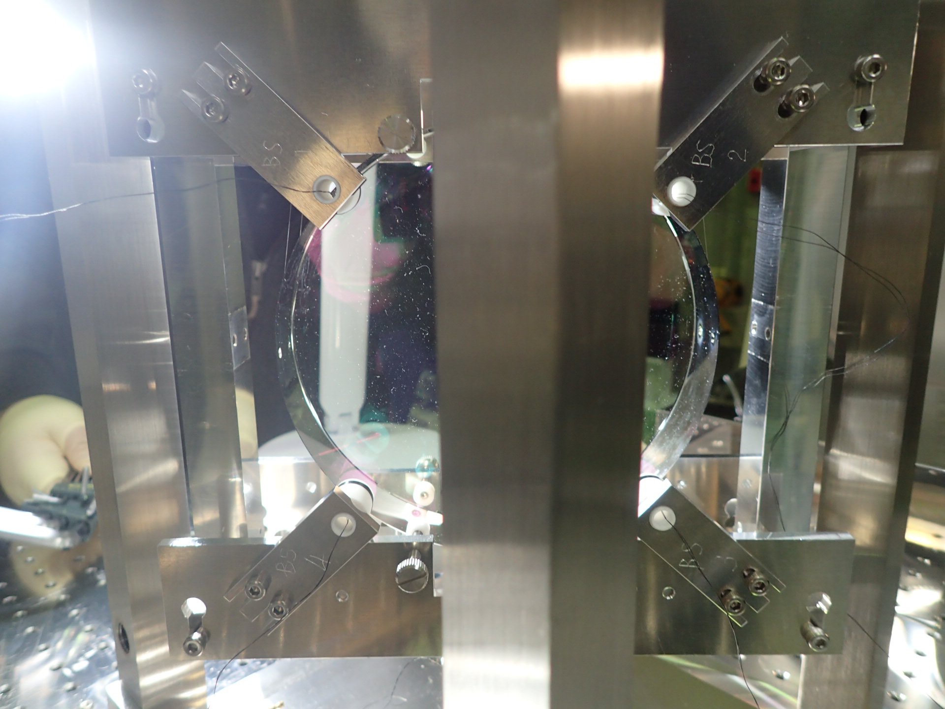
Last Friday, we installed the mirror part of the cavity,tried to align it. For doing this, firstly we add 20 kiloohm resistance to the present photo diode to increase the sensitivity at the cost of reducing the bandwidth(200 kHz). At the first try,we got multiple modes.With two mirrors and the lens, we tried to rule out higher modes and get the TEM00 one, but found out that there is misalignment in the vertical direction. After adding some piece under the mirror block, this problem has been solved, but still we cannot get rid of the effect of TEM02(TEM20) mode. We will restart the alignment again today, try to make some progress.
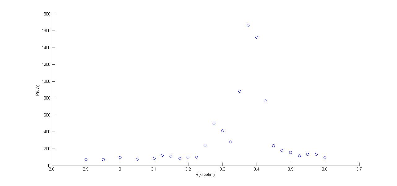
Yesterday I uploaded three figures, the first one is the green light power as a function of resistance, since we can only get the resistance from the thermal controller. Today we took smaller step of resistance changing, got better shape of the curve,and finished the convert from the resistance to temperature. The final figure shows in the attachment. We still need to do some modification of the beam to get more symmetric result.
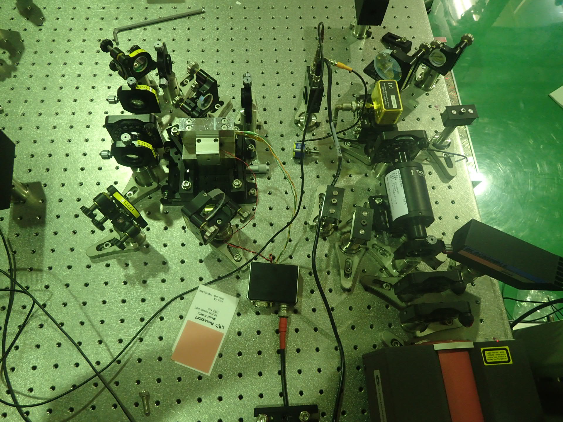
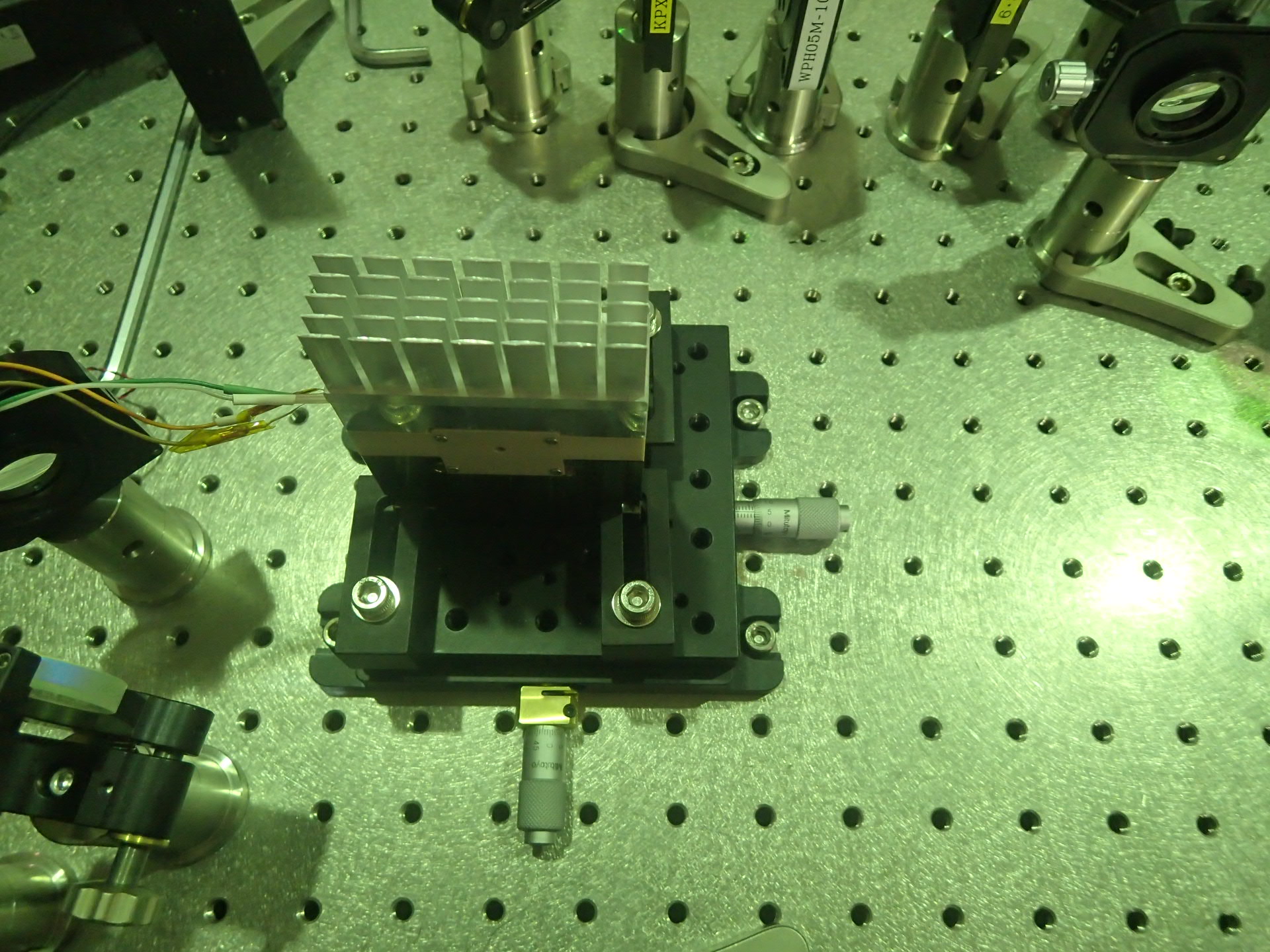
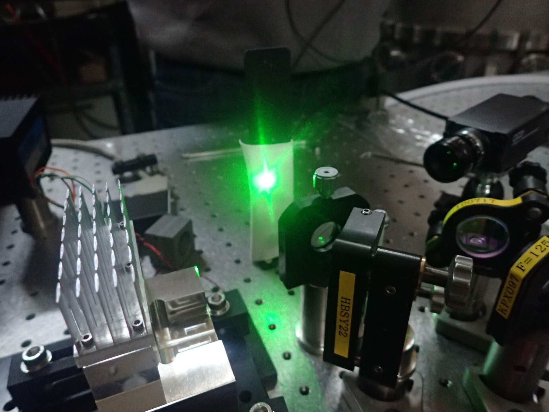
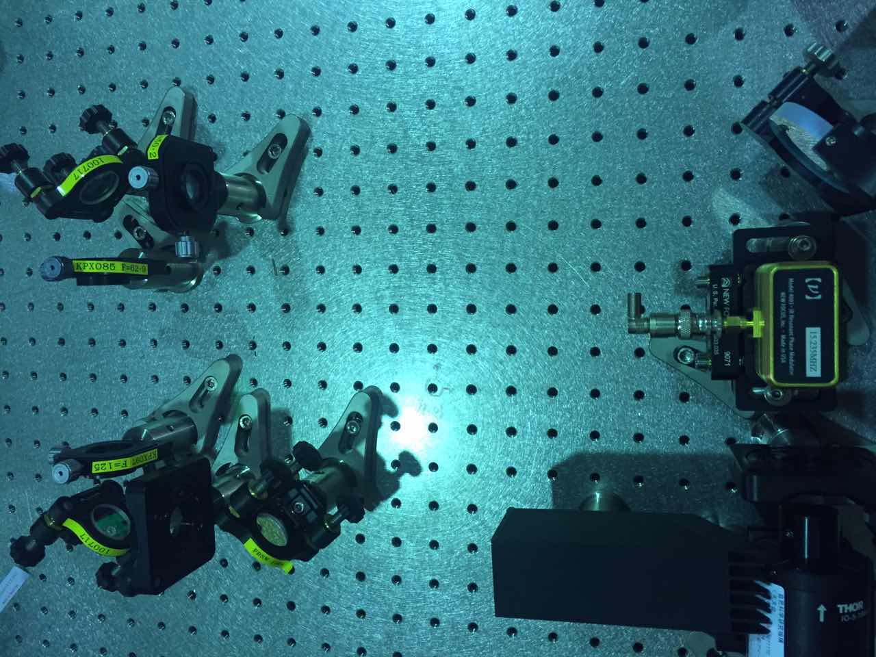
We did the clean-up of the SHG housing today, installed the crystal, mounted the harmonic beam splitter and SHG housing, and finally we got the green light. But during the process of finding the green light, we installed another half-wave plate between the second and third lens of telescope, because of the design of the SHG housing, the polarization is not we thought it should be. In the attachment you can find the situation of the optical bench now. The installation of other two harmonic beam splitter is for the power measurement of the pure green light instead of the mixture of the green and infrared.
We did three groups of measurement:
1.The relationship between the resistance(temperature) and the green light power. Since the thermal controller we are using now cannot show directly the temperature of the SHG, it can only shows the resistance. During this measurement, the diode current of the laser is 1.996A and the temperature of laser crystal is 23.63 degree. From the figure, you can find out that when the resistance is about 3.375, the power reach its peak. According to the manual of the thermal sensor, 3.011 kilo ohm response to 60 degree and 4.147 response to 50 degree. So the phasing matching temperature of the crystal is lower than what we thought it should be at 65 degree.
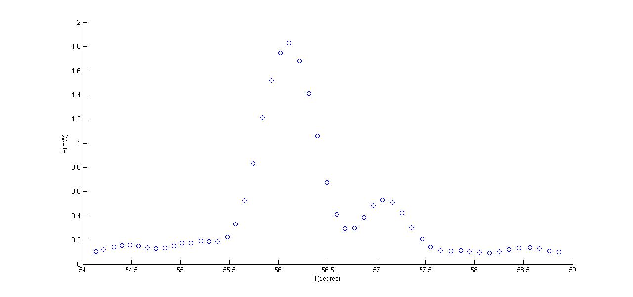
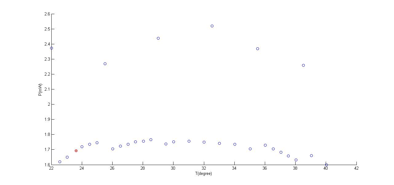
2.The relationship between the laser crystal temperature and the green light power. Under the circumstance with resistance setting to 3.375 kilo ohm. Since this kind of laser can have two modes in the same time at some temperature which will increase the power of green light to 1.5 times, these temperature points are where we should avoid. The red circle with plus marker in the figure is the temperature we used before. It is in the middle of two unexpected point, so we can still set the temperature there.
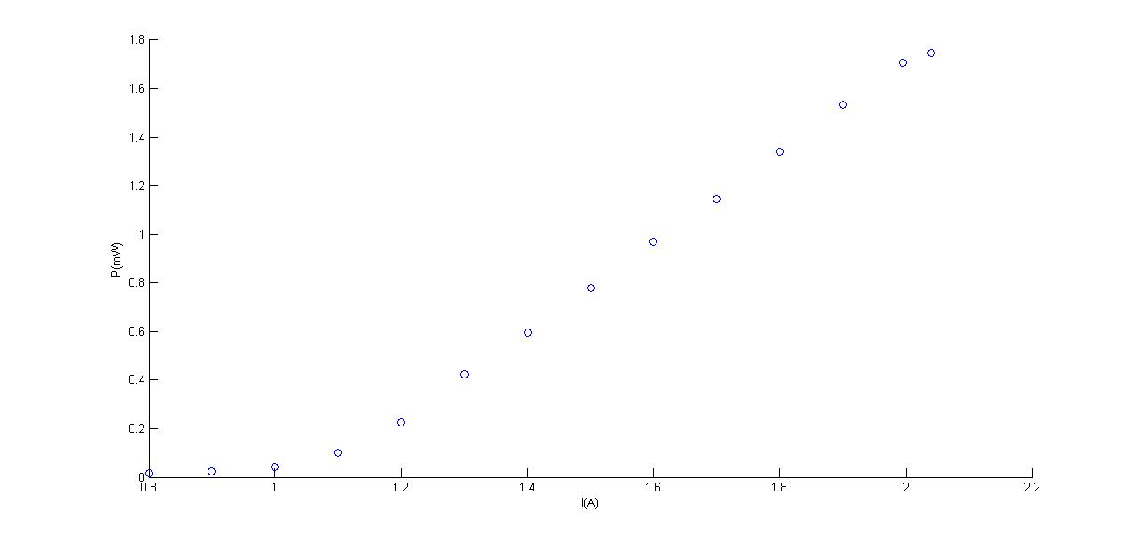
3.The last one is to show the linear relationship between the power of infrared and green, since they both linear dependent with diode current of the laser.
Members [Manuel, Matteo L.]
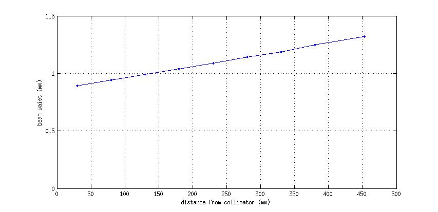
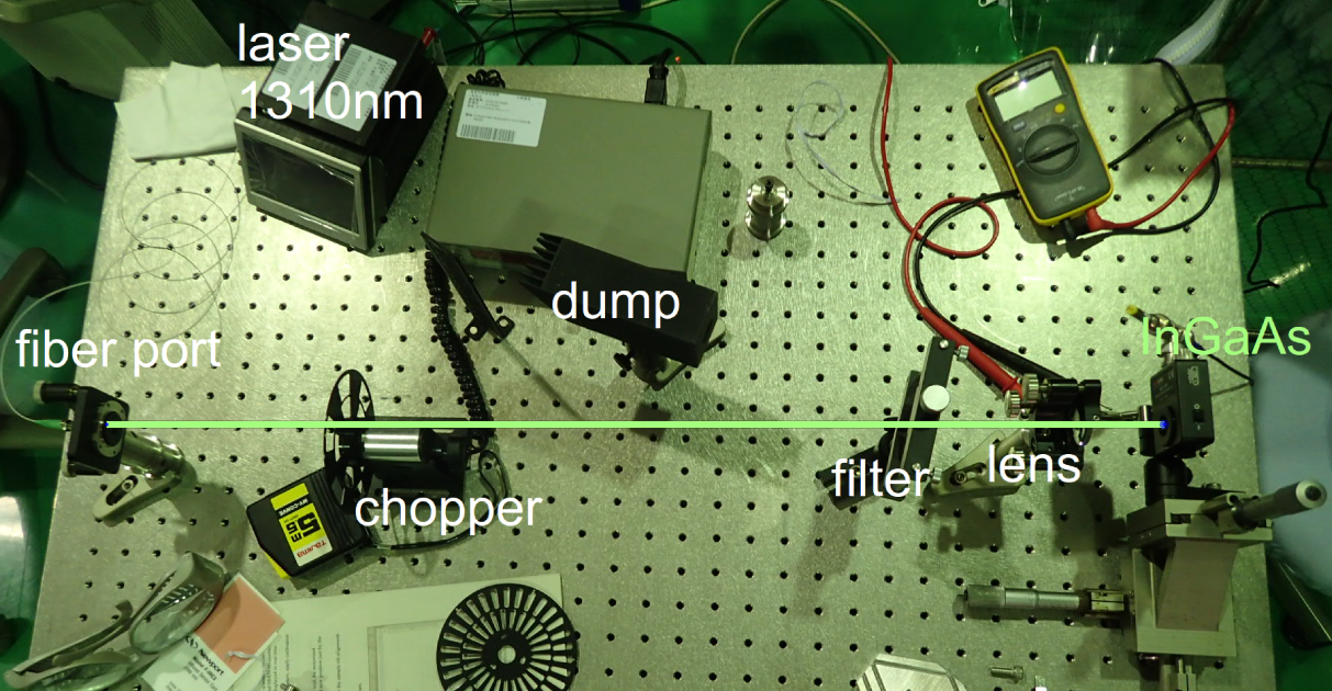
I measured the divergence of the 1310nm laser. Since the beam profiler doesn't work over 1100nm, I used the DET10N-InGaAs Detector to measure the time-dependent intensity while the beam is cut by the chopper. On the oscilloscope, I measure the rising time from 10% to 90% of the gaussian integral and calculate the waist and the divergence. I repeated for several chopper positions along the beam axis.
divergence = 1.0 ± 0.1 mrad.
waist = 420±40 um
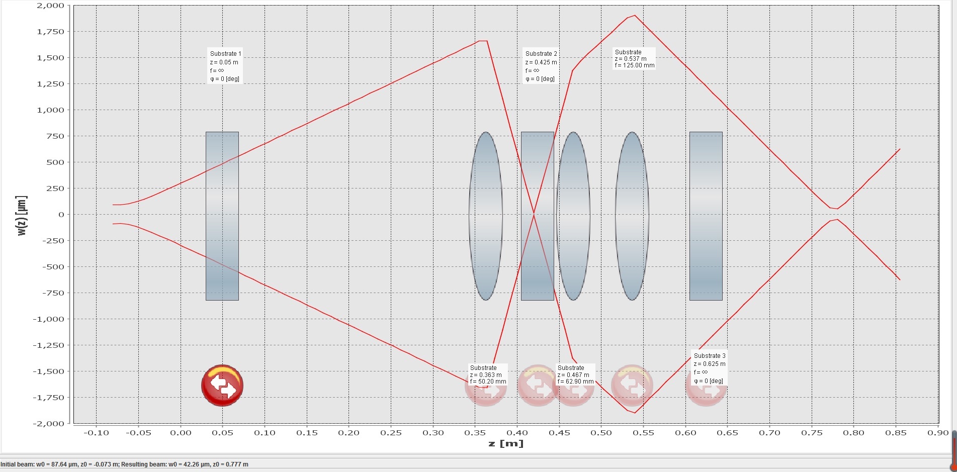
The design of the telescope did with some Matlab code, double checked with the JamMT program and it gave out a visually simulation of the telescope, showing in the attachment.During the mounting of the telescope, the maximum power of the Laser has been used. The detail of the practical telescope shows as below:
Focal length
F1--50.2mm
F2--62.9mm
F3--125mm
Distance:(Set the output of EOM as origin)
L1--37.5cm
L2--47.5cm
L3--58.5cm
Final beam waist--82.5cm
Final beam size(radius)--44.0854 micrometer
During the last check, I found out the distance between the Beamsplitter and the first turning mirror is 5cm longer the optical scheme shows, caused by my counting error of the holes.But since behind this part there are some space left, so I thought maybe we can leave it like this.

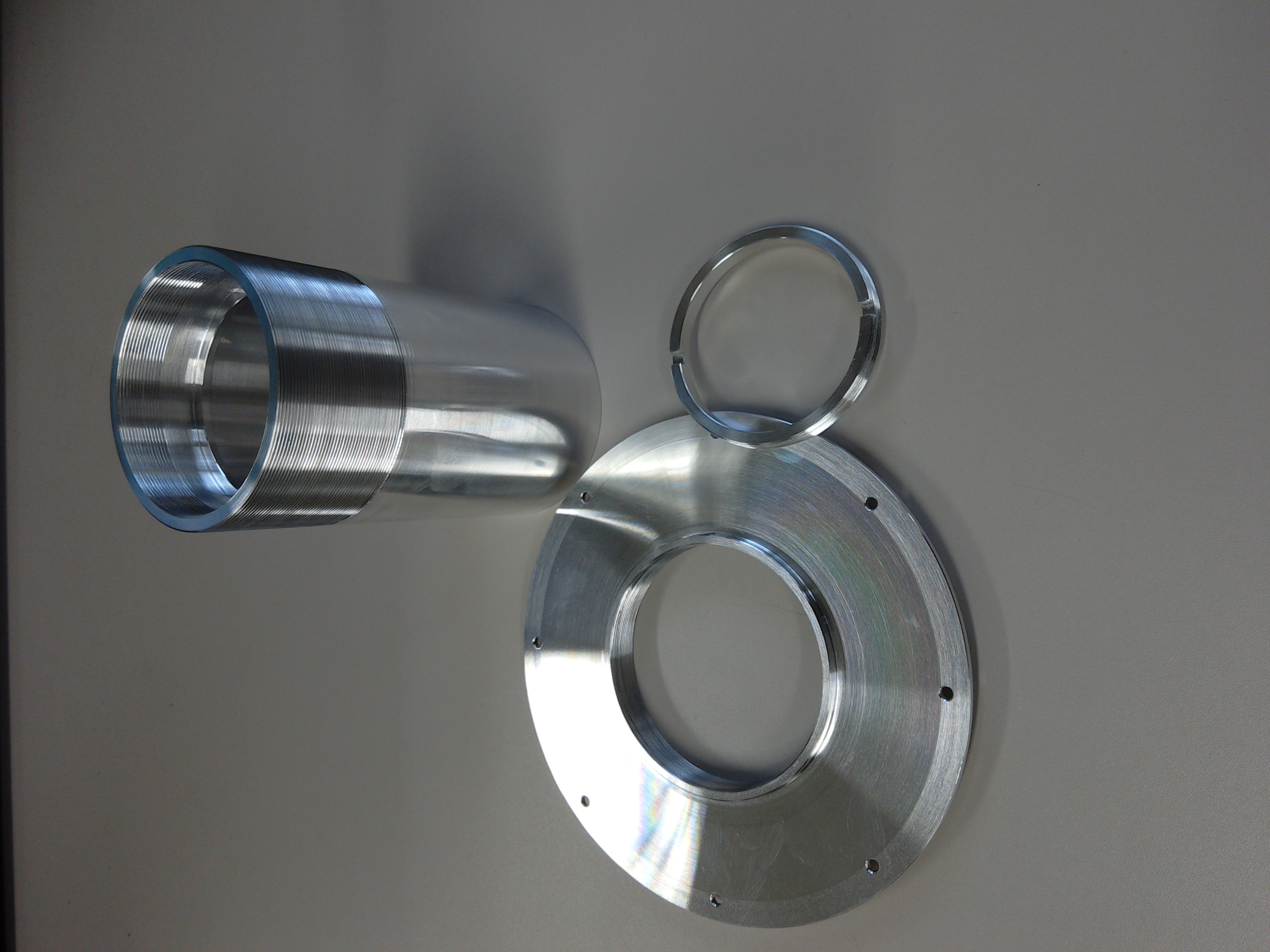
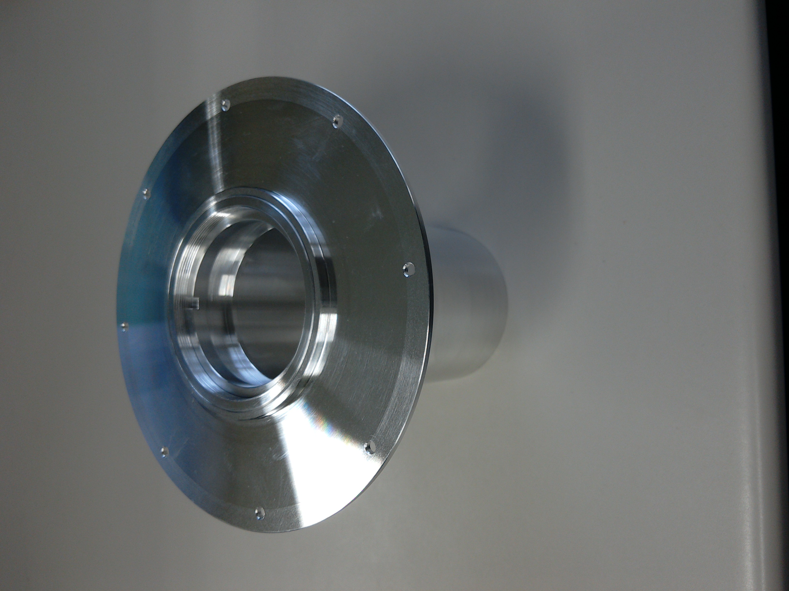
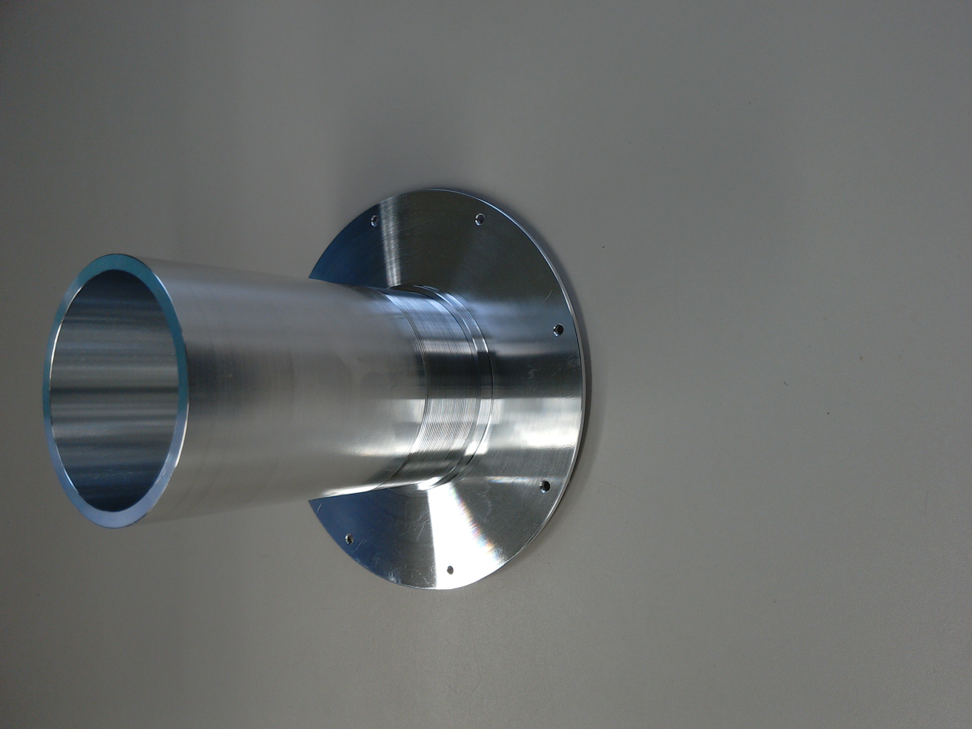
Today, the machine-shop of the ATC finished the manufacturing of the radiation shield and the window holder which are going to be attached to the inner chamber of our cryostat in the ATC. I took some photographs of the item(s). The next step would be to actually install it in the cryostat but before that I have to order some coated windows to make use of the window holder...
I finished the drawings of the setup of the OpLevs on the optical table for the BS, PR2, and PR3 mirror of KAGRA. They can be found on the JGW document server.
The new laser for the JASMINE scatterometer arrived. However, it seems that we still need some more preparations to use this instrument as no heat sink or ON/OFF switch was delivered together with the laser.
After the BS istallation, I proceed with the implementation of the local controls as it was done for the PR mirror in July.
OPTICAL LEVER
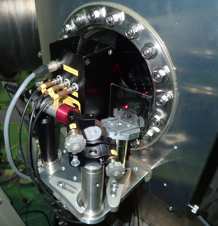
As a first thing, I restored the opltical lever (see first attaced picture). In order to have the PSD voltage sum <15, to avoid saturation, I put a filter in the laser path to reduced the power.
The power reaching the PSD is about 340 mW which corresponds to a voltage sum of 14.8 V.
TRANSFER FUNCTIONS AND CONTROL LOOPS
1) I have measured the mechanical transfer function of the mirror when exciting yaw and pich respectively (plot pag 1 and 2 of the attached document).
2) I have measured the open loop transfer function of the two degree of freedom (plot pag 3).
3) I have closed the two loops and plotted the comparison between the calibrated spectrum when the loops are open and when they are close (plot pag 4 and 5).
CALIBRATION
In order to calibrate the signal I assuemed that the PSD had the same calibration factor measured for the PSD of the same type used for the PR (see entry 276) (maybe this has to be verified..)
I follewed the same procedure explained in entry 276.
n_cal = 0.0071+/- 0.0002 (normalzed calibration)
arm = 0.60 m +/- 0.05 m
V_sum = 14.8 V
Cal_tot = n_cal/(2*arm*V_sum) = (3.04 +/- 0.26 ) e-4 [1/V]

Last friday I observed that the coil driver (#4) used to control the input mirror was not working properly. It also made the crete produce an alarm sound when connected. We have replaced it with another coild driver (#1). In order to do it, we had to restore the connector number 4 that was missing in that coil driver.
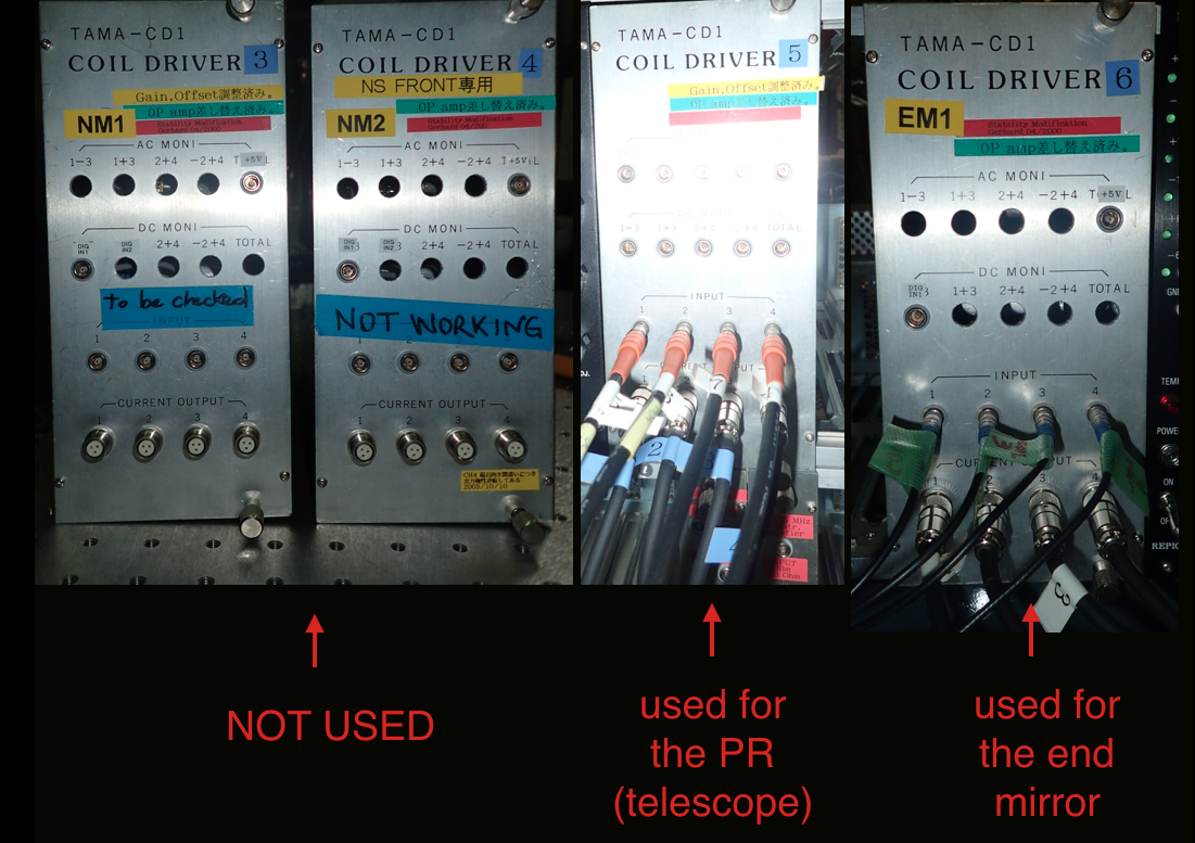
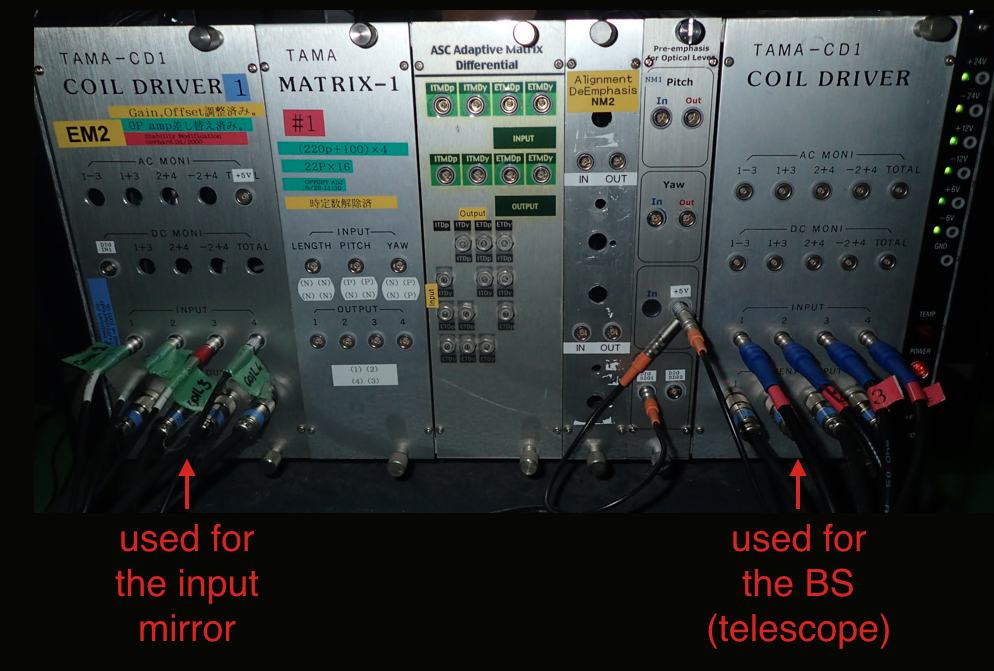
We dispose of 6 coil drivers, originally used in TAMA, which are numbered from 1 to 6. (#2 is actually not numbered)
Here a recap on the coil drivers used for filter cavity and input telescoope mirrors. (See also attached pictures)
Coil driver #1: used for the INPUT MIRROR (connector 4 was missing and had to be replaced)
Coil driver #2: used for the BS TELESCOPE (it is actually not numbered)
Coil driver #3: not used (probably is not working properly, to be checked)
Coil driver #4: not used (previously used for the INPUT MIRROR but it deesn't work anymore)
Coil driver #5: used for PR TELESCOPE
Coil driver #6: used for the END MIRROR
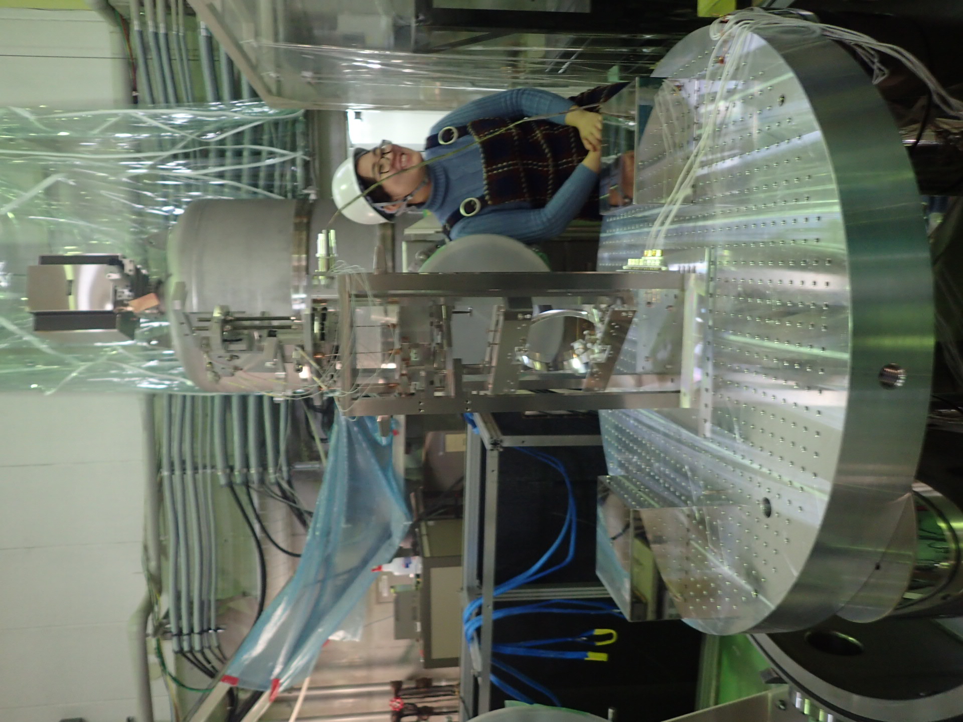
Workers: Tatsumi, Takahashi, Yuefan, Eleonora
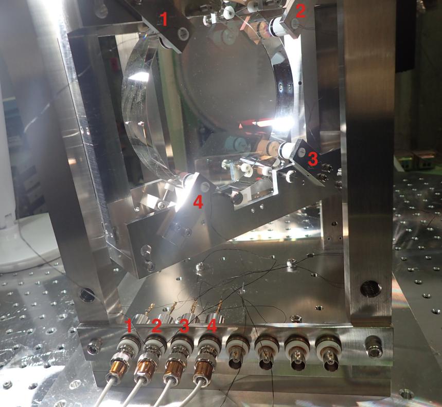
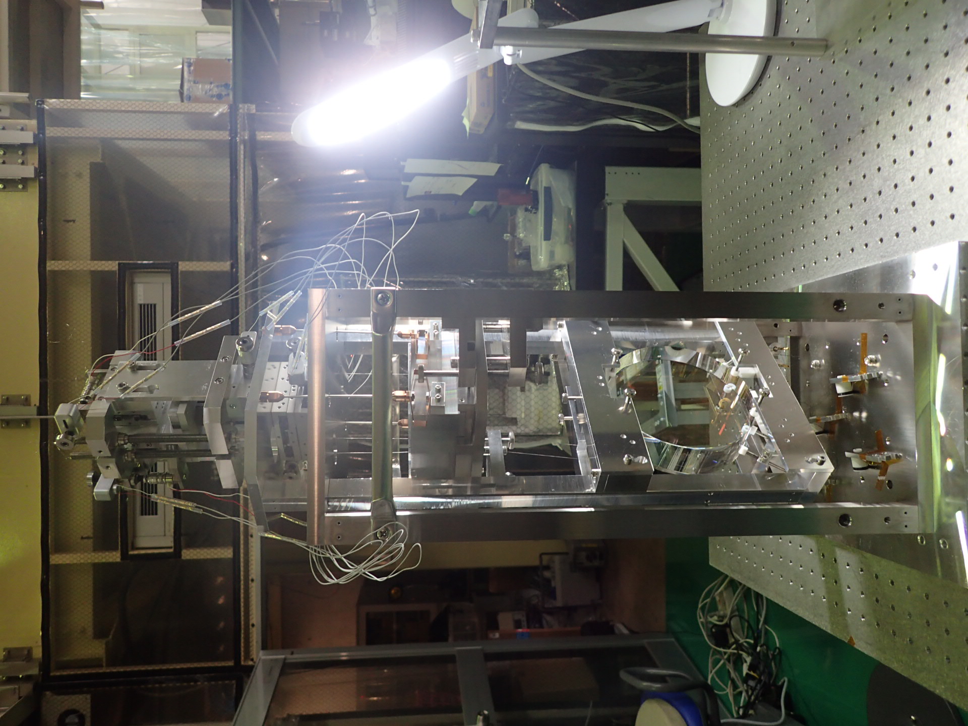
This morning the BS mirror has been successfully suspended and the suspension has been installed in the BS chamber.
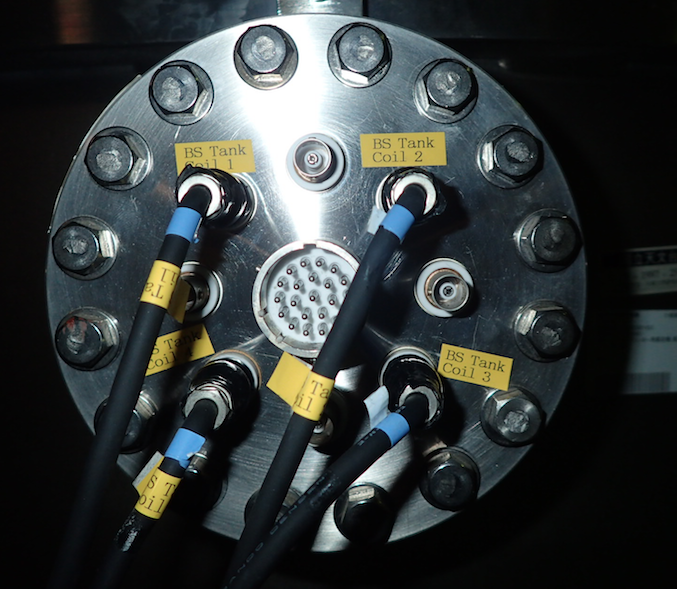
Coils have been connected as shown in the first attached picture.
Today I checked the I/O channals that will be needed for the control of the BS suspension (part of the filter cavity injection systems). Here a brief recap of the CPUs and the I/0 ports used for all the controlled suspensions. See also first picture in the attached file.
INPUT MIRROR (4 input , 4 output)
CPU: SAS_NM1b (133.40.121.74) in central room
INPUT : SC1 MOD 6 /ai 4:7
OUTPUT: DEV1 /ao 0:3
TELESCOPE MIRRORS BS ans PR (4 input, 8 output)
CPU: SAS-NM2b (133.40.121.78) in central room
INPUT: SC1 MOD 3 /ai 0:7 (1, 2 used for PR 5,6 used for BS) NB: #4 doesn't work!
OUTPUT DEV2 /ao 0:7 (1, 2, 3, 4 used for PR 5, 6, 7, 8 used for BS)
END MIRROR (4 input, 4 output)
CPU: SAS-EM2a (133.40.121.75) in end room
INPUT: SC1 MOD3 /ai0:3
OUTPUT: PXI1 Slot3/ao 0:3
NB: Some days ago I had to change the port in the swtch that was connecting the CPUs in the central room to the network. I found out that the port used previusly (see attached picture 2) didn't work anymore and that was the reason why I wasn't able to connect the supervisor PC to the remotes targets.
Workers: Tatsumi, Takahashi, Yuefan, Eleonora
During the installation work, one standoff was dropped off from the mirror.
[Glueing work]
Tatsumi made glueing work for standoff at TAMA.
[Next]
We will make installation work on Thursday afternoon.