NAOJ GW Elog Logbook 3.2

| Current (A) | Temperature (deg) | |
| CC | 1.183 | 38.16 |
| P pol | 1.338 | 32.5 |
After the sample N1 was mounted, a set of measurements was performed, with a pump power of 10.6 W on the sample.
We found that a parasitic reflection from the red probe is propagating back towards the IR line. We fixed the problem by slightly moving the diaphragm in front of the chopper. This does not affect the power measured by the power meter
Calibration with reference sample.
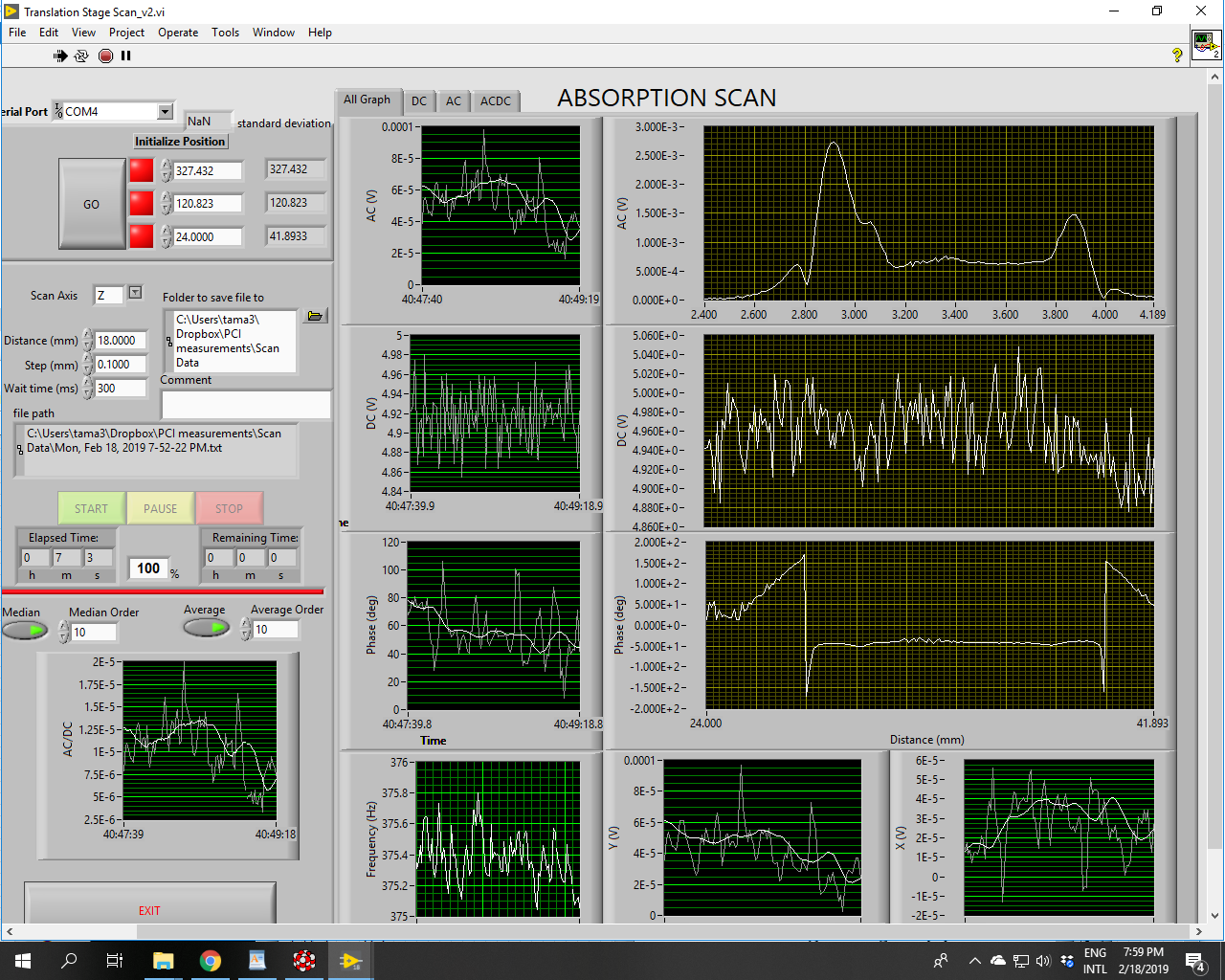
Position of the detection stage: 70 mm
Pump power: 34 mW * sqrt(0.55) = 0.02521 W
Probe Beam alignment: DC probe maximized at 4.85 V
AC signal at scan center = 0.08 V
Z stage alignment: surface peak maximum at Z =38.85
R = AC/DC/Abs/P = 0.63
Sample N1
DC level 4.92 V
P = 10 W (current = 7.5 A)
Power transmitted 9 W
Power incident 10.54W
T=9/10.54=0.854
Previous results confirmed (Fig 1). All OK.
Sample S1 mounted.
Transmitted power = 9 W
Preliminary absorption estimate:
AC/DC/P/sqrt(0.85)/R*3.34= 0.00175/4.25/10/sqrt(0.85)/0.63*3.34 = 237 ppm/cm
but DC was not maximized... to be done again
Figure 2
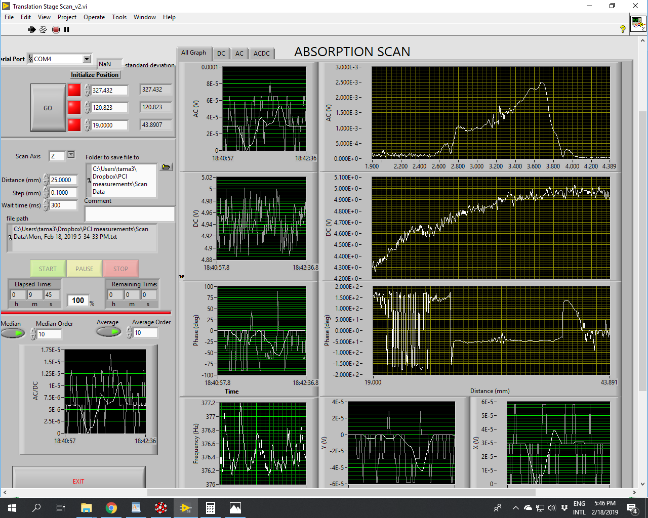
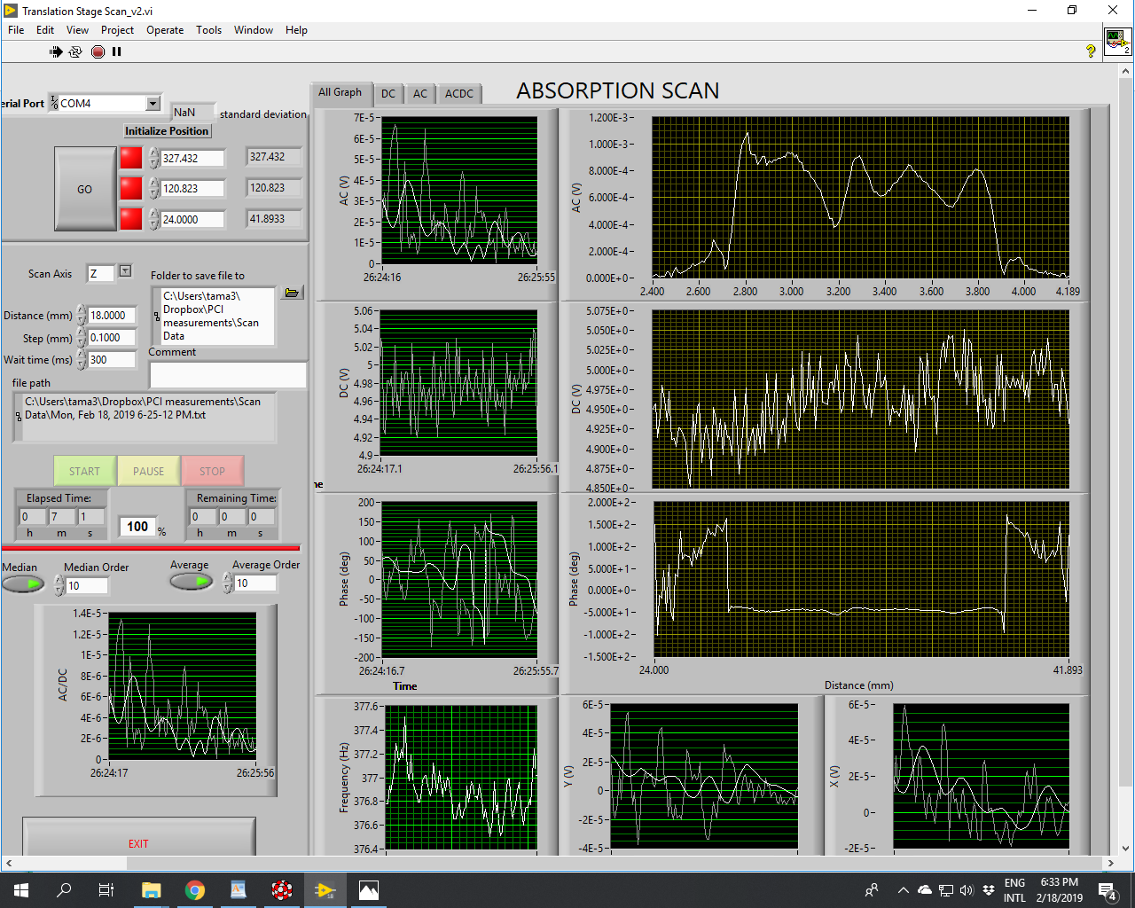
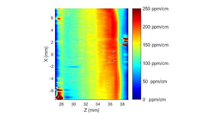
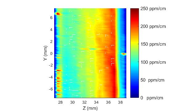
Sample S2 Mounted
Transmitted power = 9 W
Preliminary absorption estimate:
AC/DC/P/sqrt(0.85)/R*3.34= 0.001/4.95/10/sqrt(0.85)/0.63*3.34 = 116 ppm/cm
Figure 3
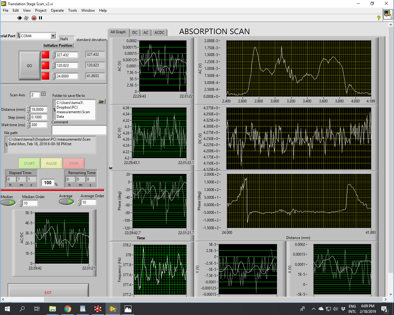
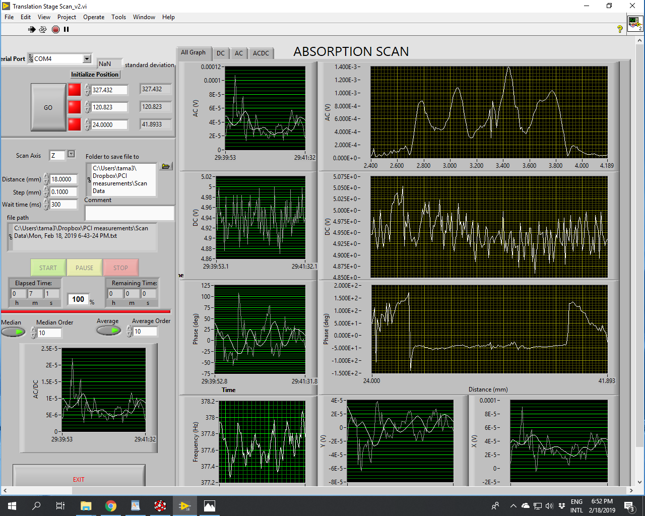
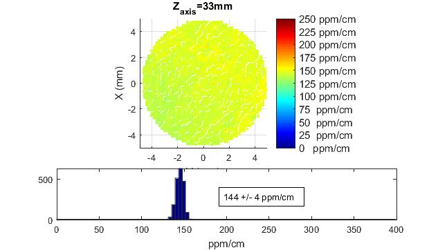
Sample S3 Mounted
Transmitted power = 9 W
Preliminary absorption estimate:
AC/DC/P/sqrt(0.85)/R*3.34= 47 - 163 ppm/cm
Figure 4
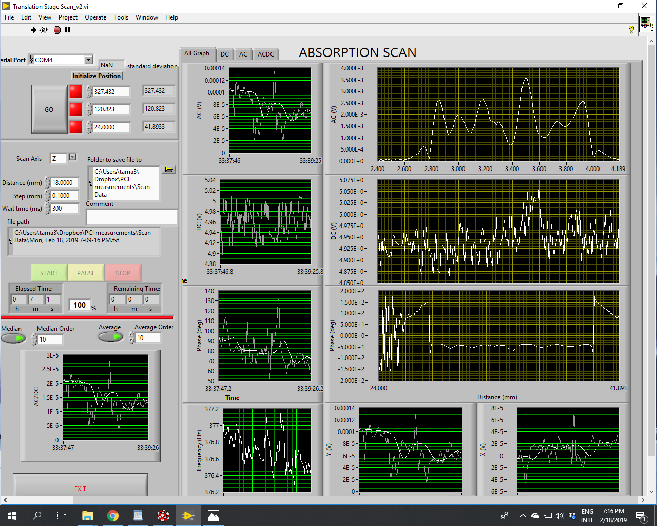
Sample S4 Mounted
Transmitted power = 9 W
Preliminary absorption estimate:
AC/DC/P/sqrt(0.85)/R*3.34= 81 - 406 ppm/cm
Figure 5
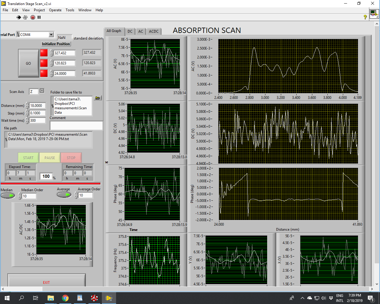
Sample S5 Mounted
Transmitted power = 9 W
Preliminary absorption estimate:
AC/DC/P/sqrt(0.85)/R*3.34= 115 - 287 ppm/cm
Figure 6
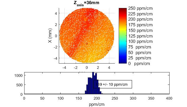
Sample S6 Mounted
Transmitted power = 9 W
Preliminary absorption estimate:
AC/DC/P/sqrt(0.85)/R*3.34= 80 ppm/cm
Figure 7
Participant: Marco and Yuhang
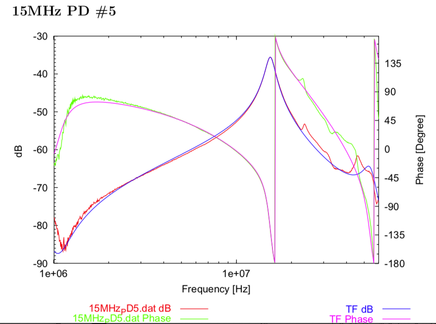
Since we suspected the OPO reflection signal may be too much and saturate PD. We decided to use TAMA PD. Because:
1. It separates DC and AC. So there is less probability of saturation.
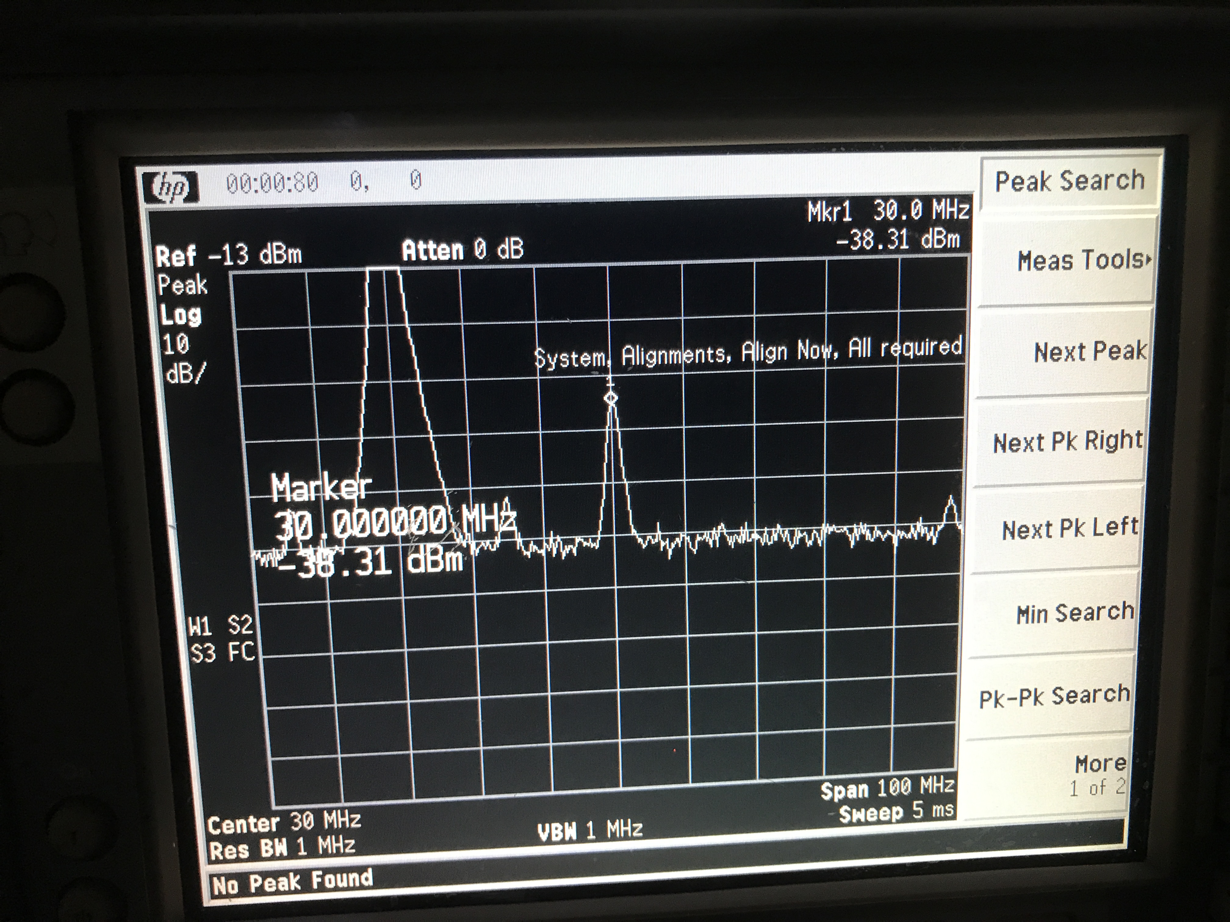
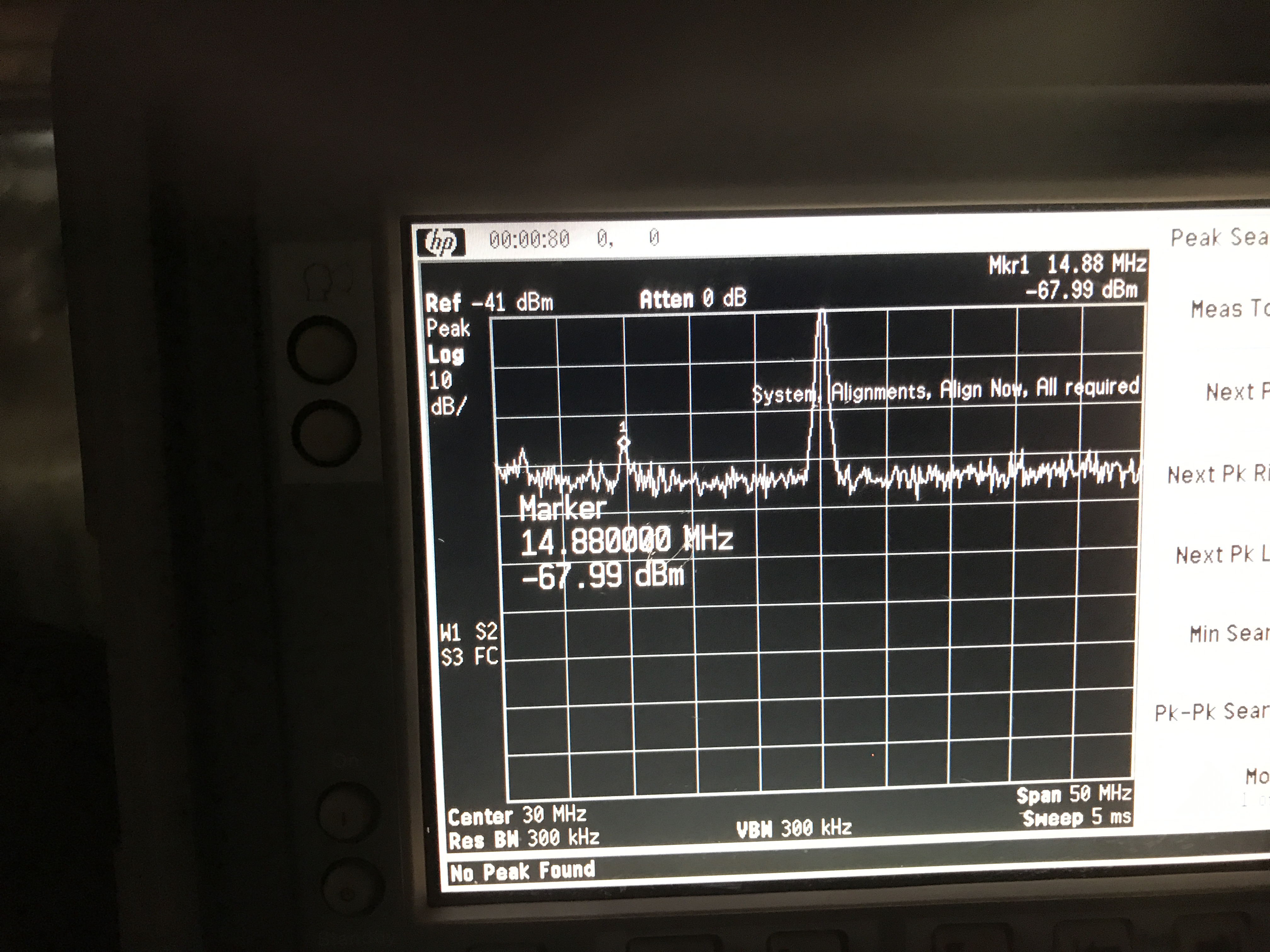
2. TAMA PD amplifies signal around 15MHz. We can see that it also amplifies 14MHz quite a lot from the attached figure.
However, even after replacement, we cannot see useful information from OPO reflection. And even after reflection demodulation, we cannot see.
Anyway, we can check more things to confirm.
Participant: Marco, Aritomi, and Yuhang
1. We replaced the OPO transmission PD by PDA10CS. The new PD has a bandwidth of 17MHz so that we can see the oscillation of coherent control error signal(should be 14MHz).
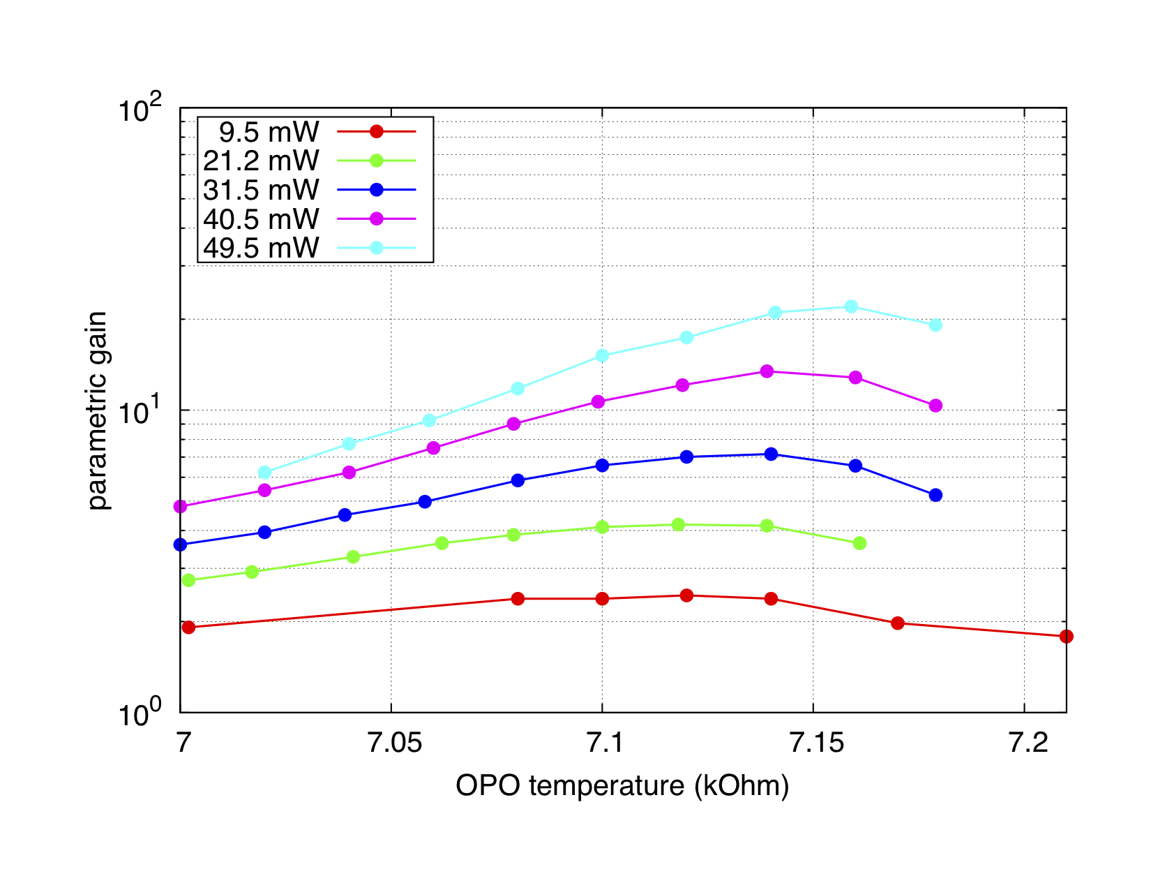
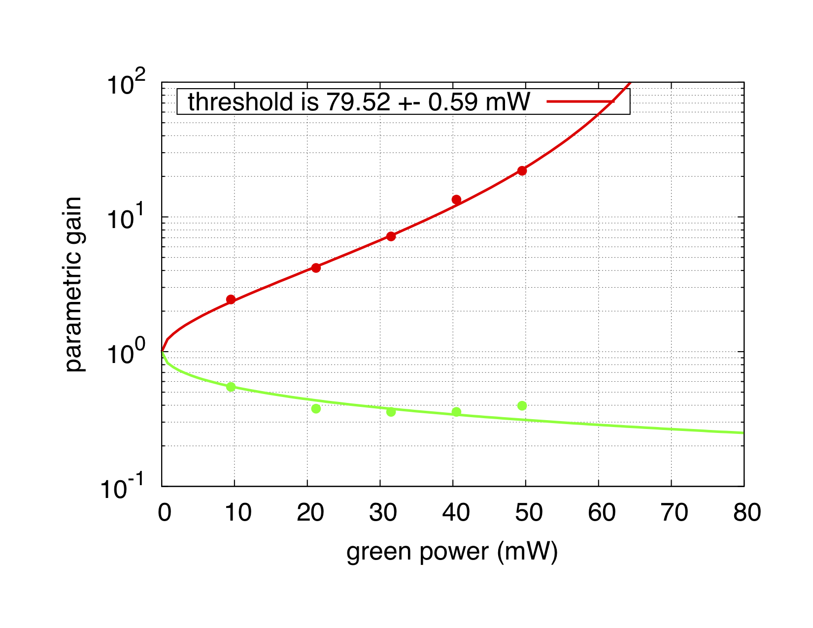
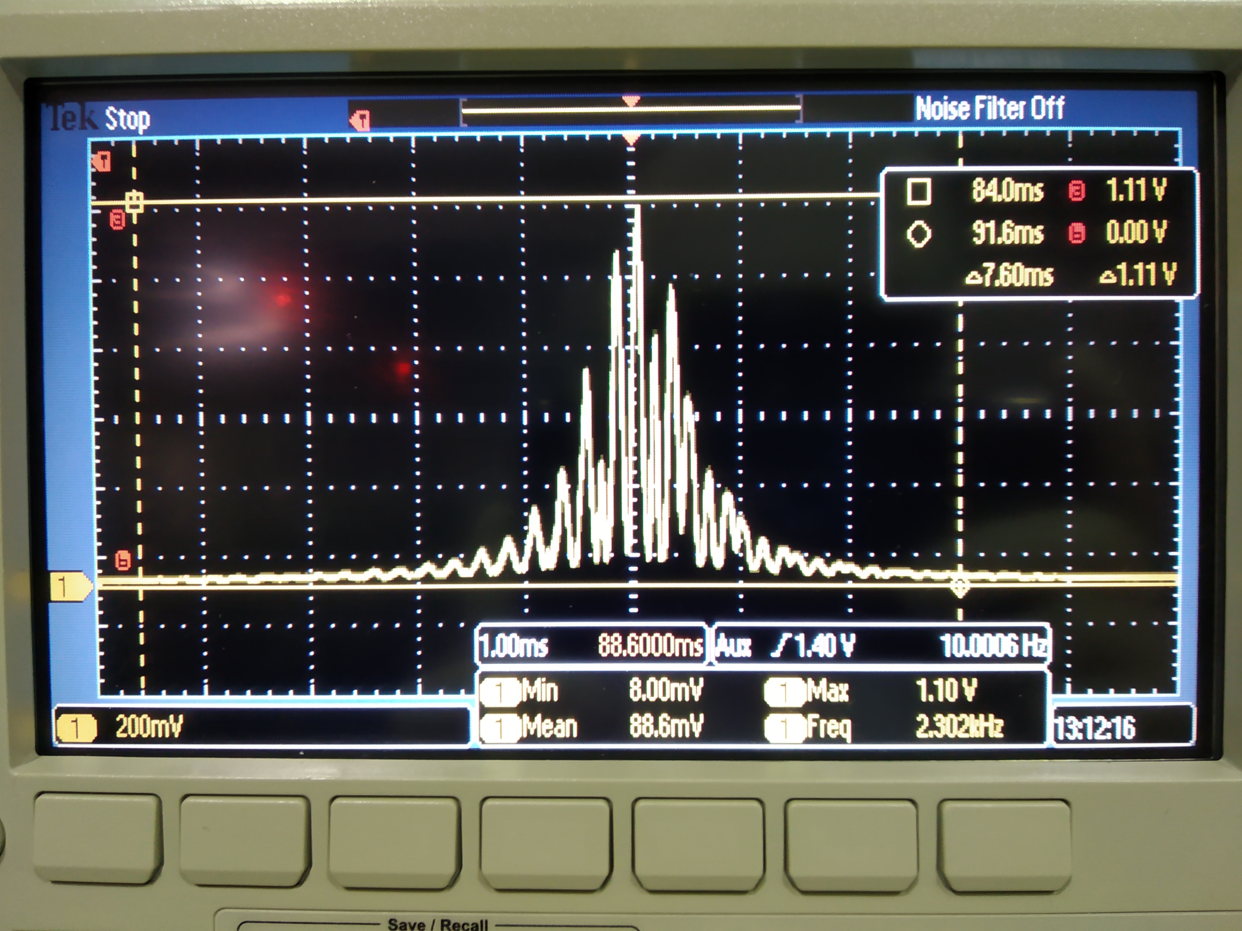
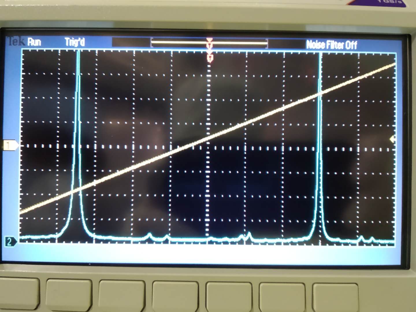
2. Then we brought back BAB and aligned it with OPO scanning and green phase scanning. Here the green phase scanning with 1kHz and 2Vp-p. This parametric amplification effect is not obvious when the modulation magnitude around 1Vp-p. However, we see many fringes within 1ms. This means 2 Vp-p corresponds to the scanning depth is more than 1 period. See attached figure 1.
We also make BAB and p-pol peak overlap when we scanning OPO. We wrote down the p-pol PLL frequency shift. It is 30.5MHz. In this case, green power is 51mW. OPO temperature is 7.03kOm. In principle, this frequency difference will be always like this if we keep green power and OPO temperature. Then we lock p-pol PLL.
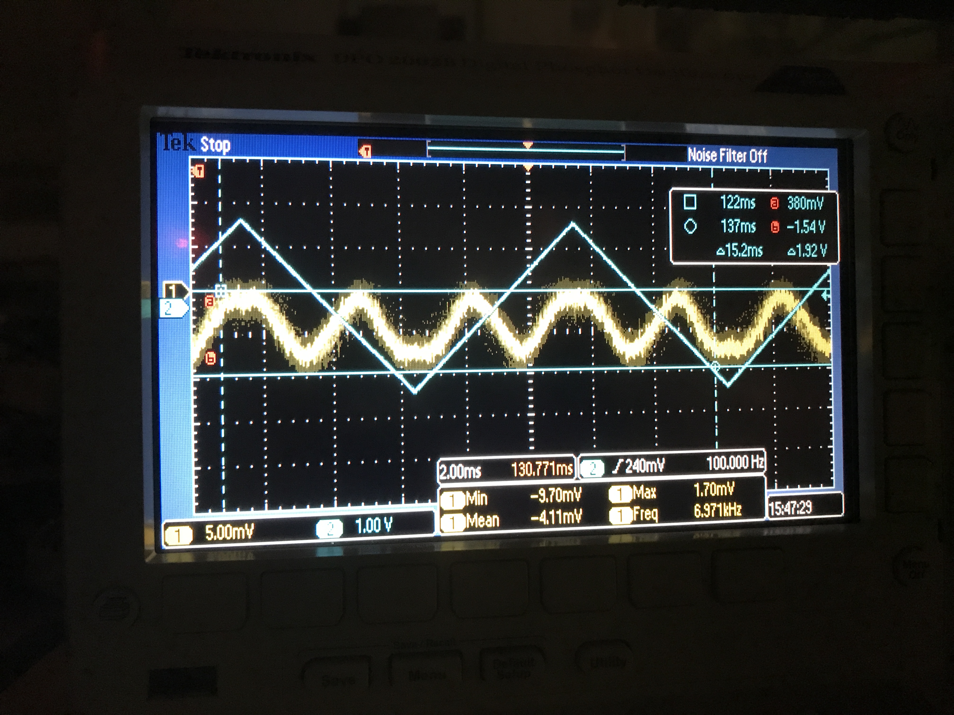
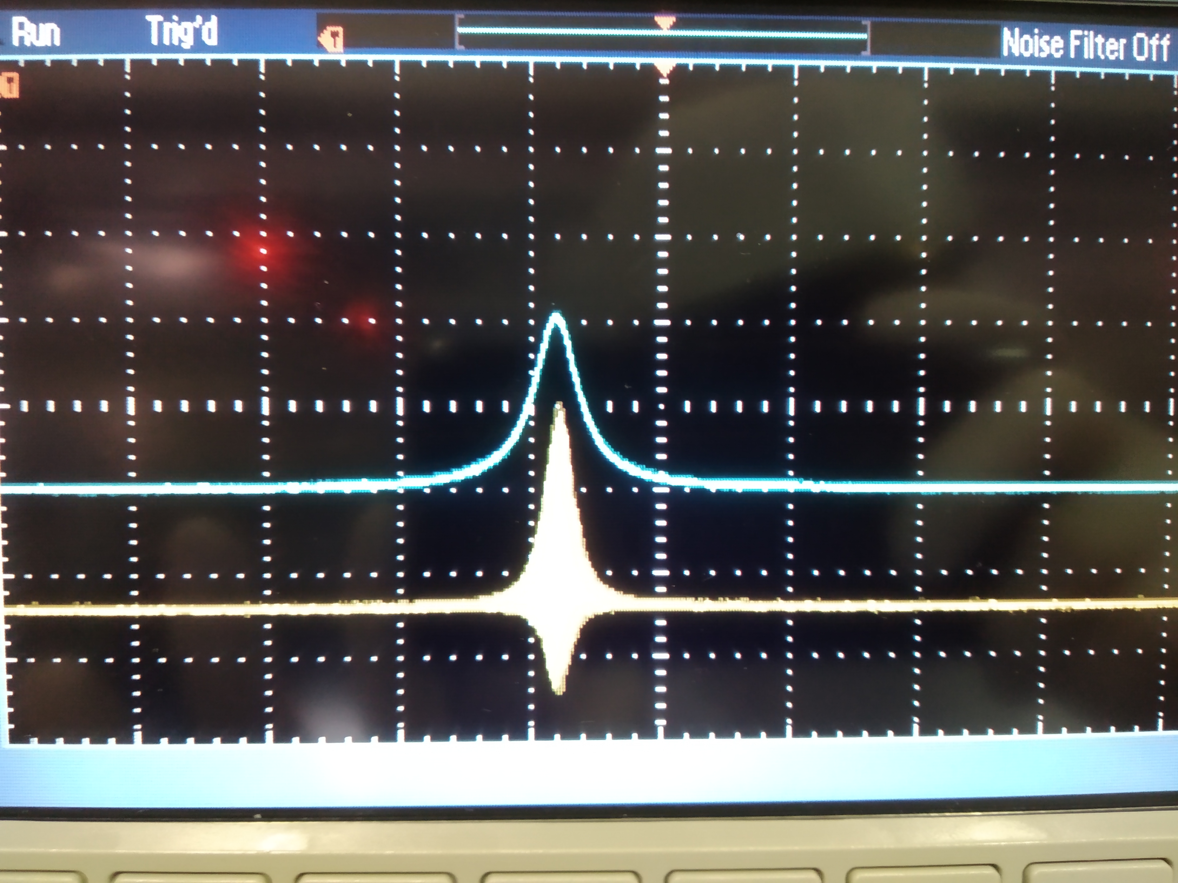
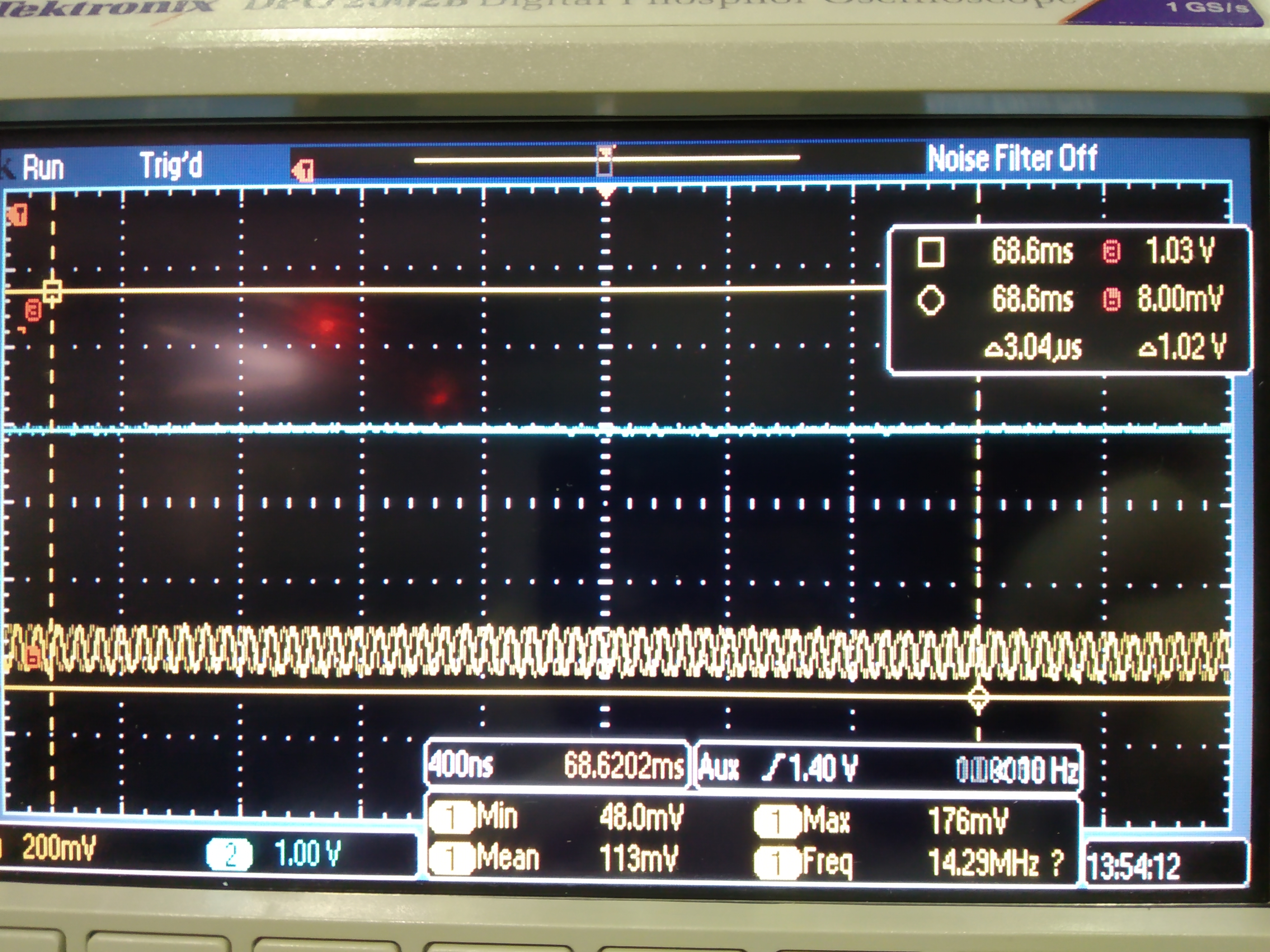
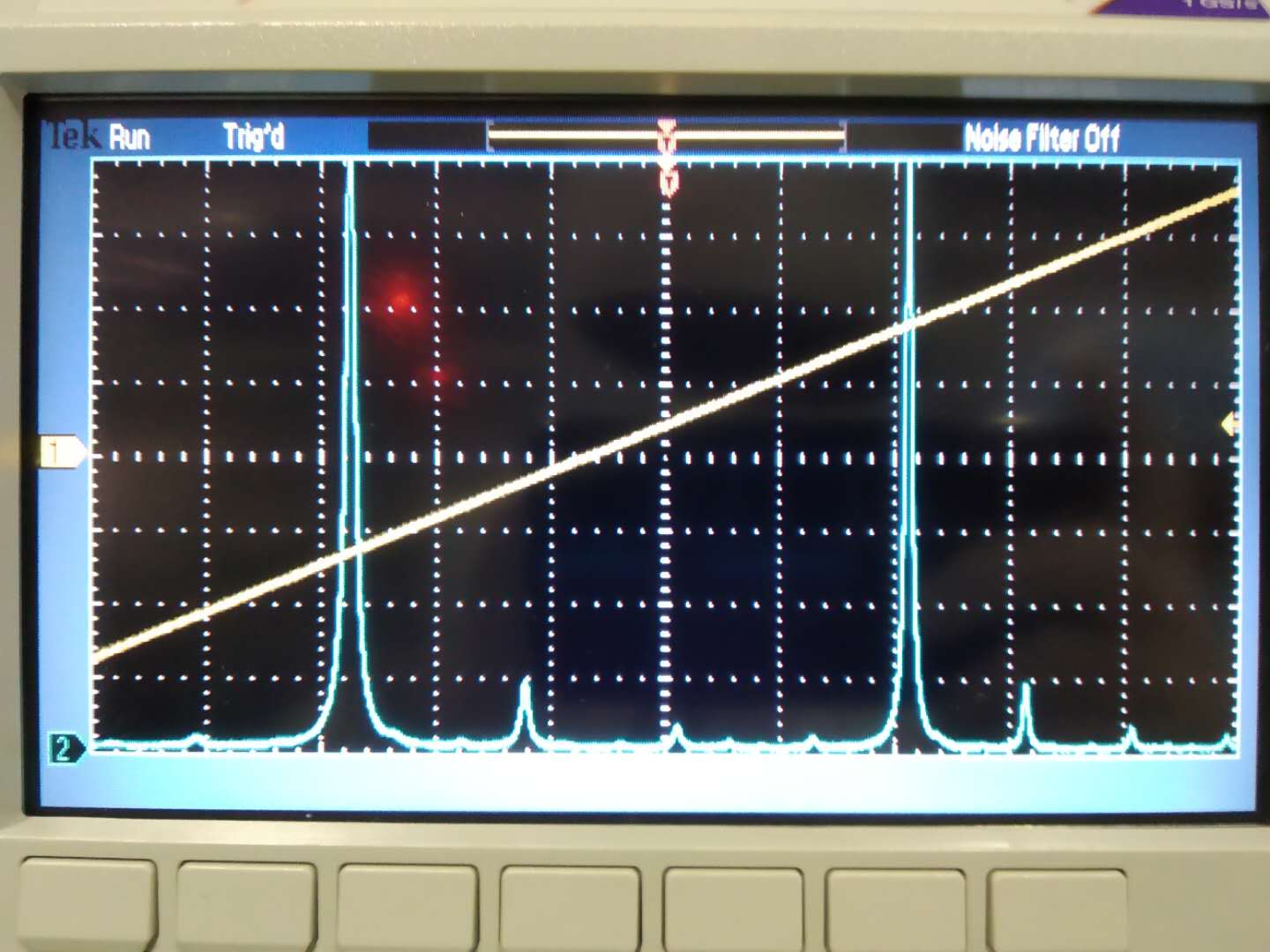
3. Then we replace BAB with coherent control beam. Lock PLL with 7MHz. As soon as we did that, we found a phenomenon in the attached picture 2. It seems there is a very clear oscillation at high frequency. After we lock OPO and we look into the detail of this oscillation. We found this oscillation is around 14MHz. See attached picture 3. It seems the coherent control signal we are looking for. However, we found a not understandable error signal after we did the demodulation. Because we found the error signal didn't change oscillation frequency after we changed the green phase scanning frequency. So further investigation needs to be done.
4. We didn't see any useful information from OPO reflection.
We have noticed the nonlinear effect became worse for the second time of CC error signal checking. This proofs that we should consider more about how to apply coherent control.
Participant: Marco and Yuhang
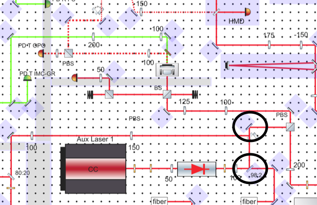
We found a sudden movement of the mirror while we were doing the experiment. We think two mirrors are suspicious, which are used for coherent control laser alignment. Because the alignment of p-pol didn't change, we think the guess above is reasonable.
The suspicious mirrors are marked with black circles in the attachment. Next time, we should try to recover alignment by moving only one mirror. So that we can know which one is causing the problem and replace it.
The fork is properly fixed.
We tried to make s PLL working for 7MHz. At the same time, make p and s co-resonant. Then shift 7MHz of p. This is the procedure to lock PLL.
However, we found a good setting for that procedure brought us mode-hooping of p.
In the end, we found the temperature of OPO was changed accidentally from 7.05 to 7.9. After we brought back the temperature, we can lock PLL for coherent control without mode-hooping.
Next step is to check coherent control error signal. However, the reflection power drop for resonance is still not visible up to now.
[Aritomi, Yuhang, Marco]
We found optimal temperature region which doesn't have mode hopping for three lasers and has beat note with 7 MHz for ML-CC PLL and below 400 MHz for ML-p pol PLL and overlapping of CC and p pol inside OPO.
| Current (A) | Temperature (deg) | |
| Main Laser | 1.834 | 23.12 |
| CC | 1.183 | 38.18 |
| P pol | 1.338 | 32.43 |
P pol beat note when CC and p pol is overlapping inside OPO is 69.8 MHz without green.
With green power of 68 mW, p pol overlapping beat note is around 7 MHz. The laser setting is as follows.
| Current (A) | Temperature (deg) | |
| Main Laser | 1.834 | 23.12 |
| CC | 1.183 | 38.1 |
| P pol | 1.338 | 32.41 |
We have to lock p pol at p pol beat frequency +- 7 MHz, so p pol beat note around 7 MHz is not good. To change the p pol beat frequency, we changed OPO temperature from 7.05 kOhm to 7.02 kOhm. The p pol beat frequency became 56 MHz.
It's very stable with slow loop.
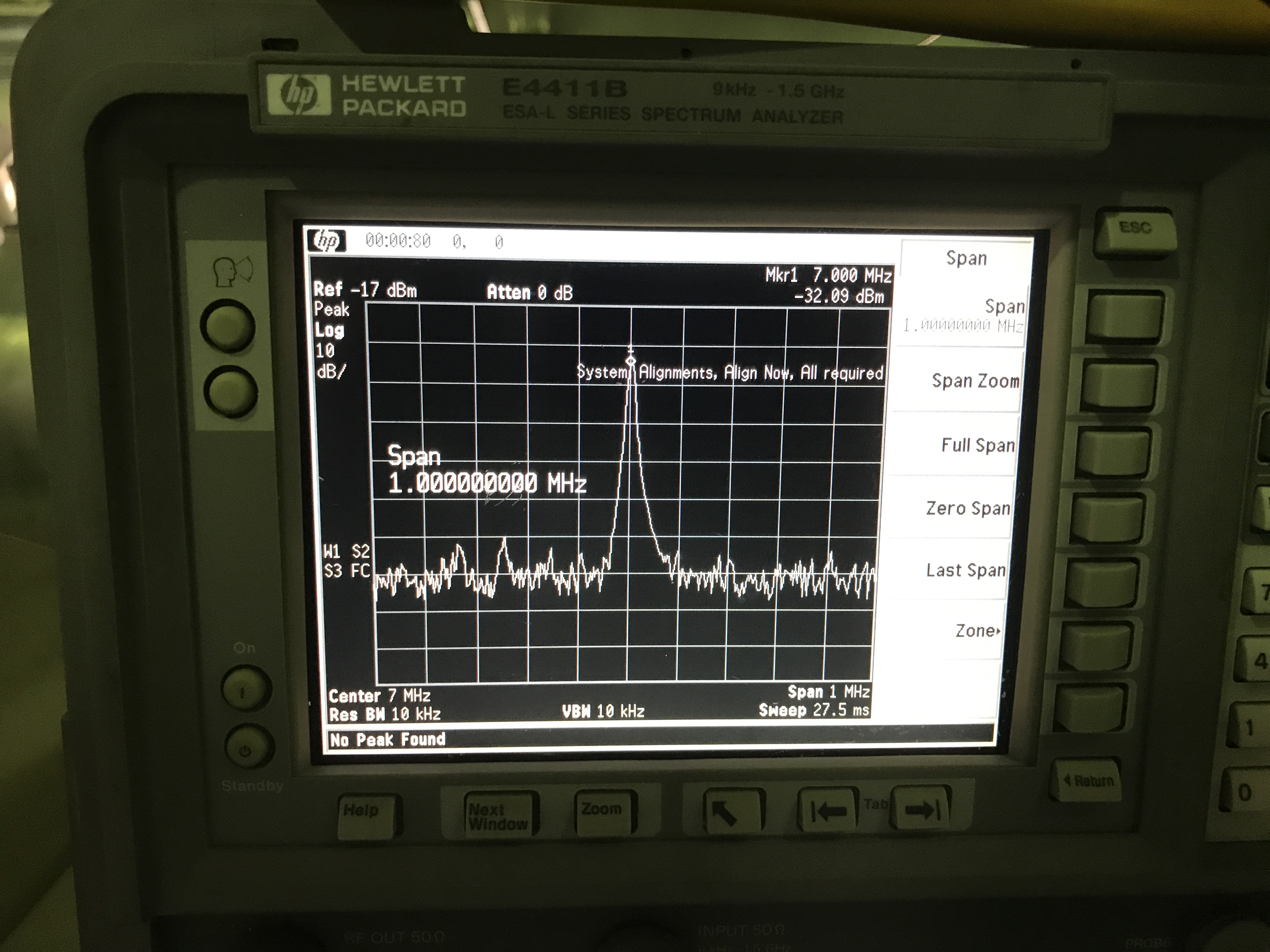
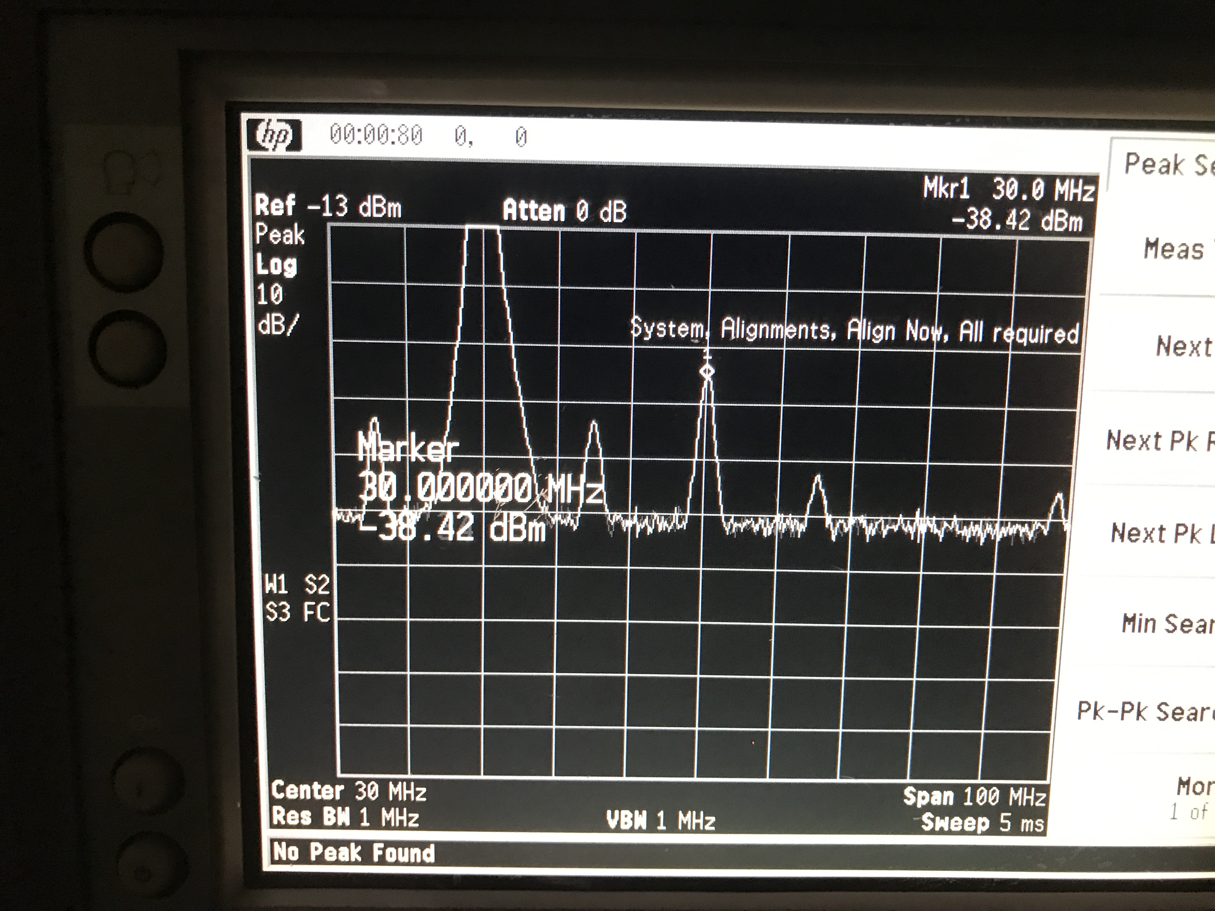
First attached picture shows spectrum of locked beat note.
|
sideband amplification
|
20.8 dB
|
8.8 dB
|
0 dB
|
| beat note |
-38 dBm
|
-38 dBm
|
-38 dBm
|
|
lower sideband
|
-45 dBm
|
-52 dBm
|
-66 dBm
|
|
upper sideband
|
-55 dBm
|
-60 dBm
|
-
|
We can lock SHG with both 8.8 dB and 0 dB amplification, but SHG locking is not good for 0 dB amplification. So we decided to use 8.8 dB amplification.
p pol and main laser: PN1064R5F2
s pol and main laser: TN1064R5F2A
Participant: Eleonora and Yuhang
As we said during the last filter cavity meeting, the matching of s-pol inside OPO is becoming worse. Today we checked again and found something different. Especially we checked the shape of the first higher order mode. And another important effect is the higher order mode becomes higher after moving screws for yaw. All of these prove that the higher order mode is because of yaw misalignment.
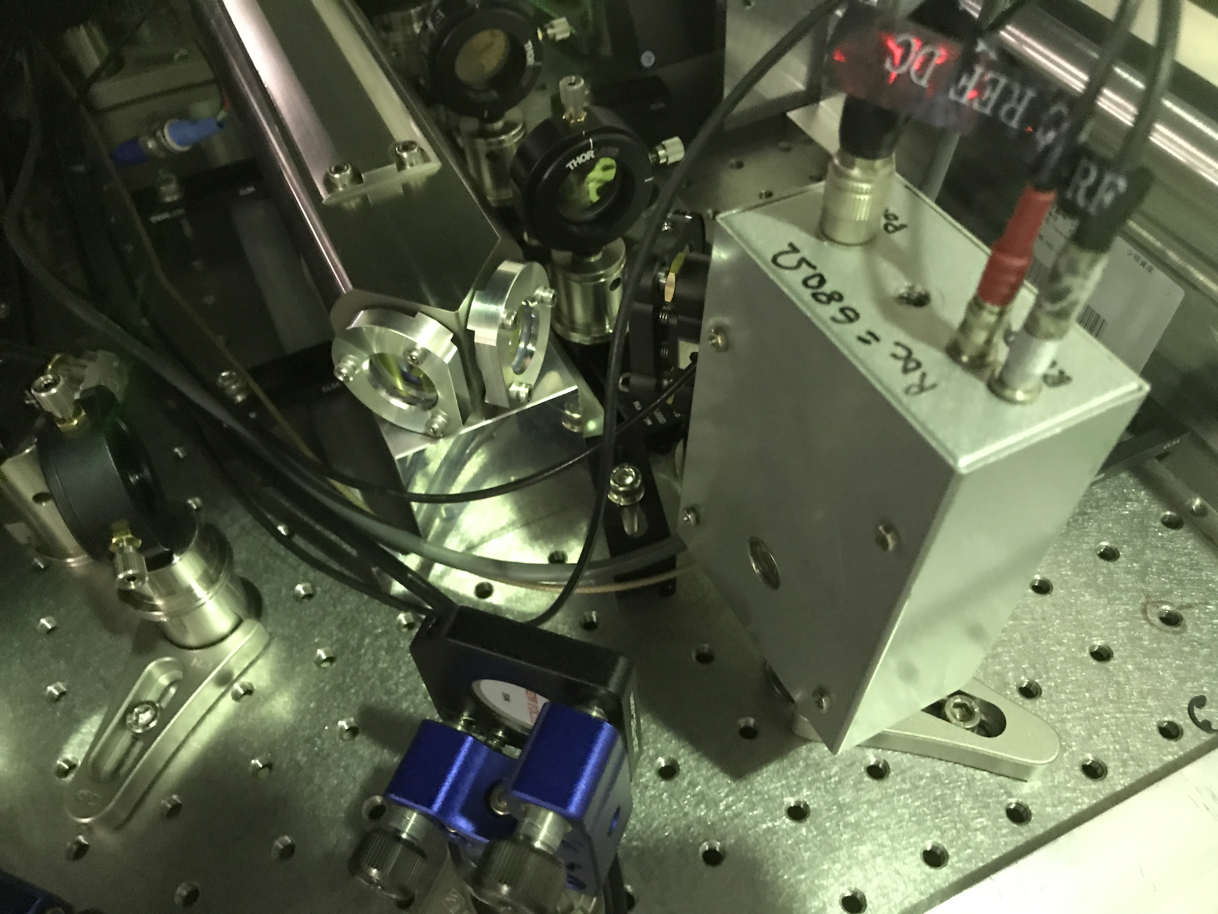
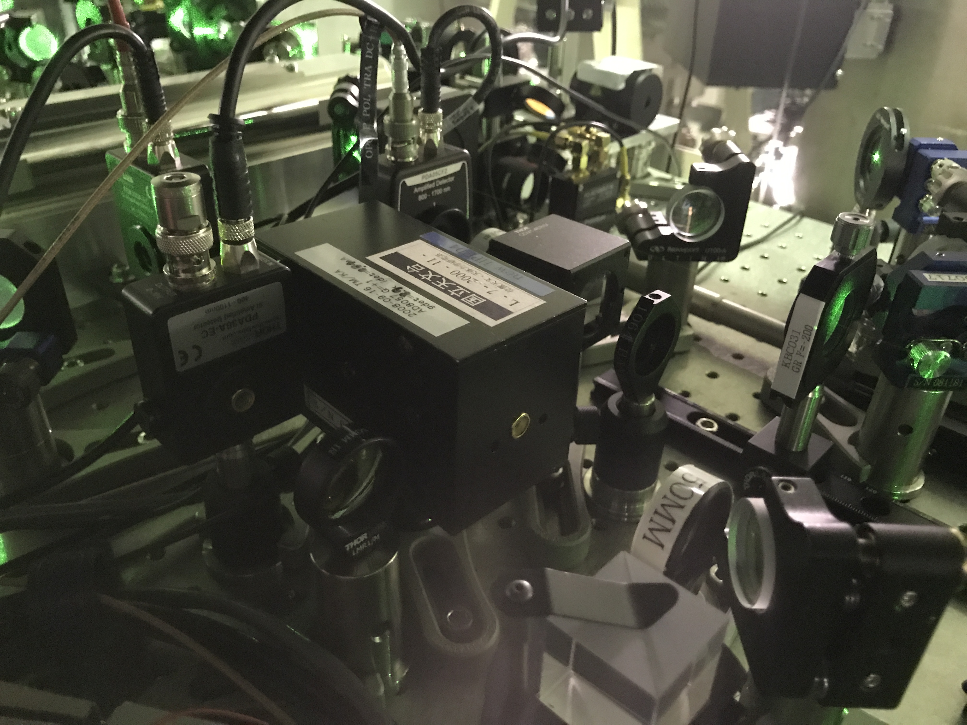
Then we aligned s-pol and also p-pol. The alignment condition is taken as a photo and attached. The first one is for s-pol and the second one for p-pol.
0.5 m LEMO-SMA x 2
2 m SMA-SMA x 2
5 m LEMO-SMA x 2
Please check the cable before you use it !
Since we found that we cannot lock PLL, I did the test of PLL by sending signal inside and checking output signal.
The PLL servo box contains
| Input | local oscillator, beat note |
| output | fast control, slow control, mux |
| function | filter, integrator(switchable) |
(Before doing test, we succeed in connecting computer and servo. We also succeeded in writing a desirable command to servo.)
Input signal:
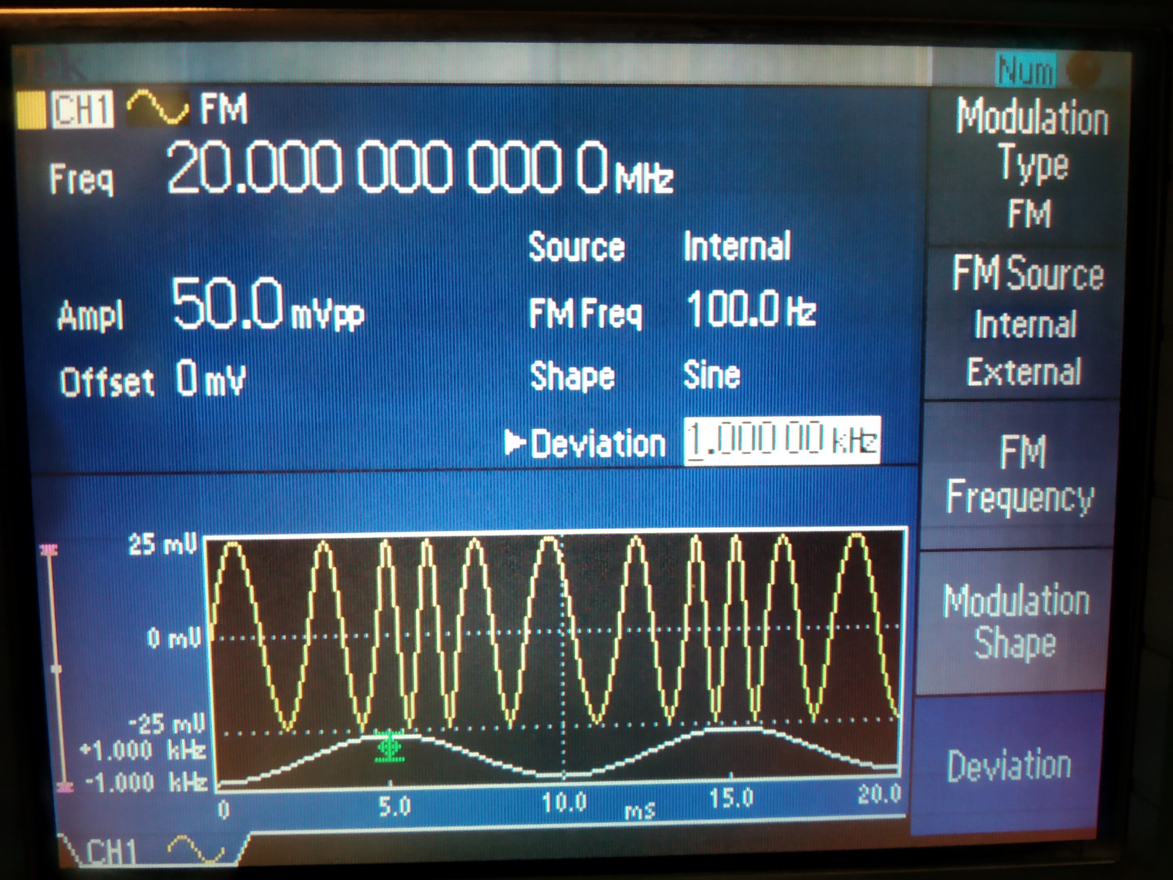
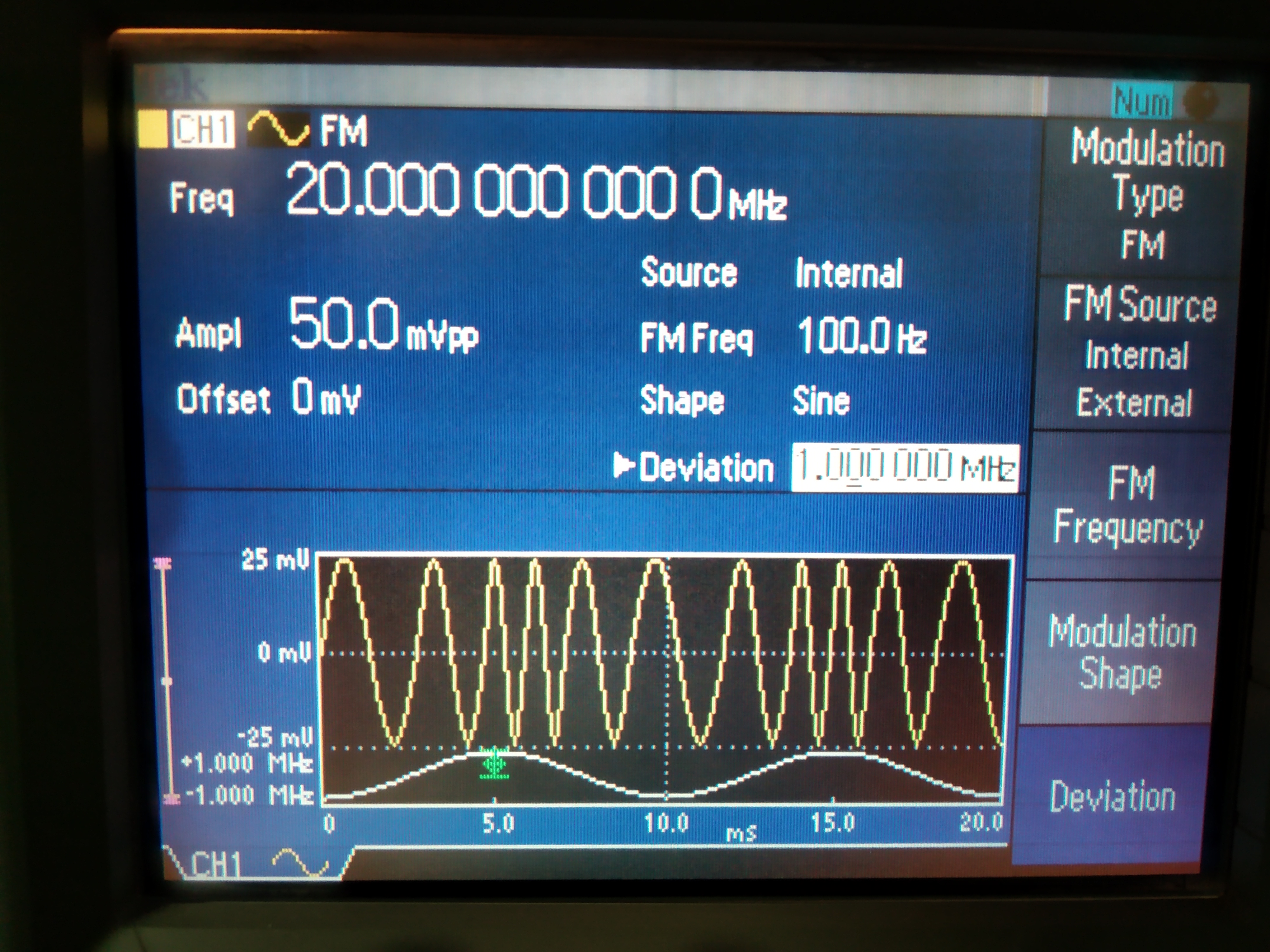
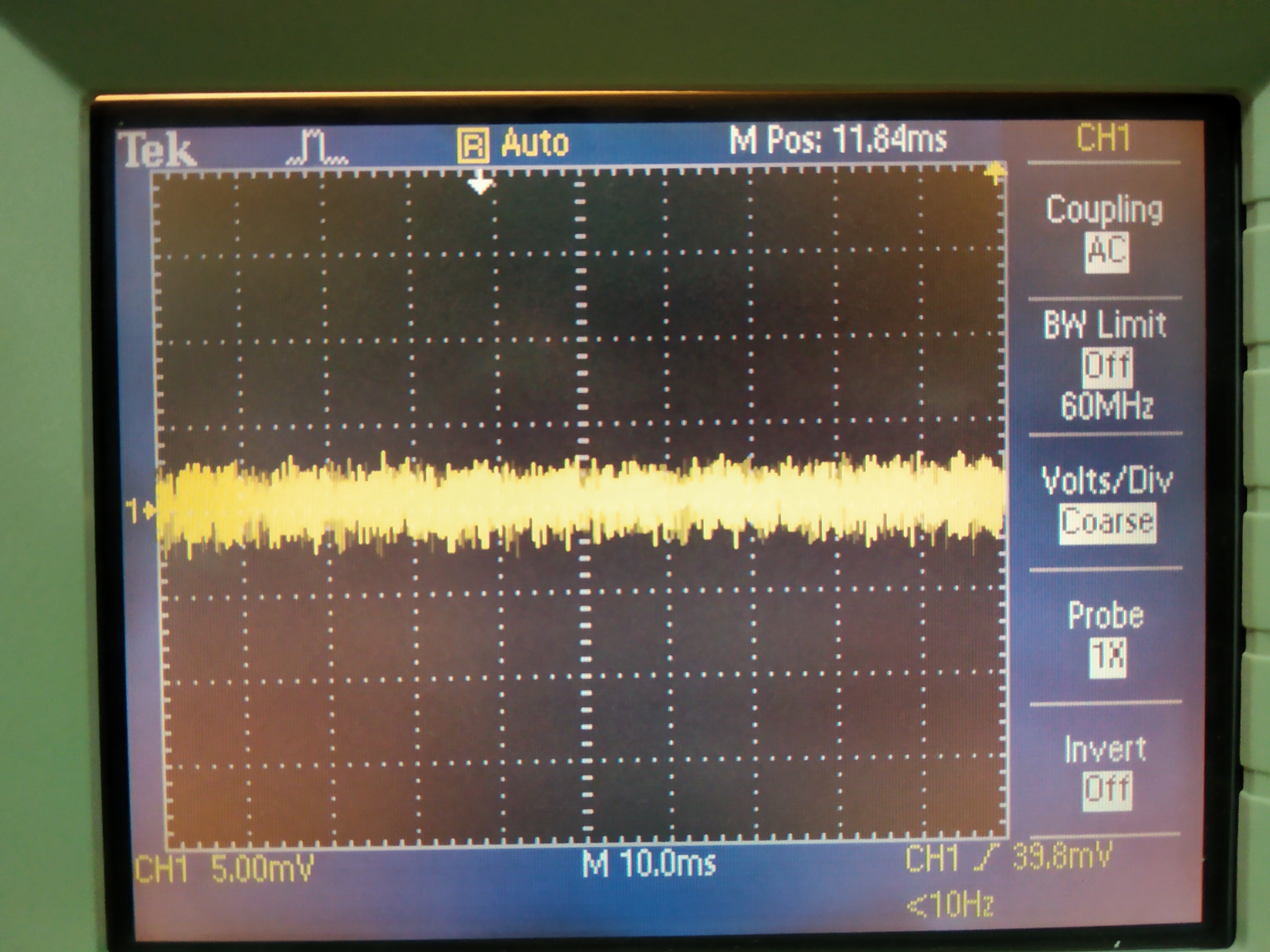
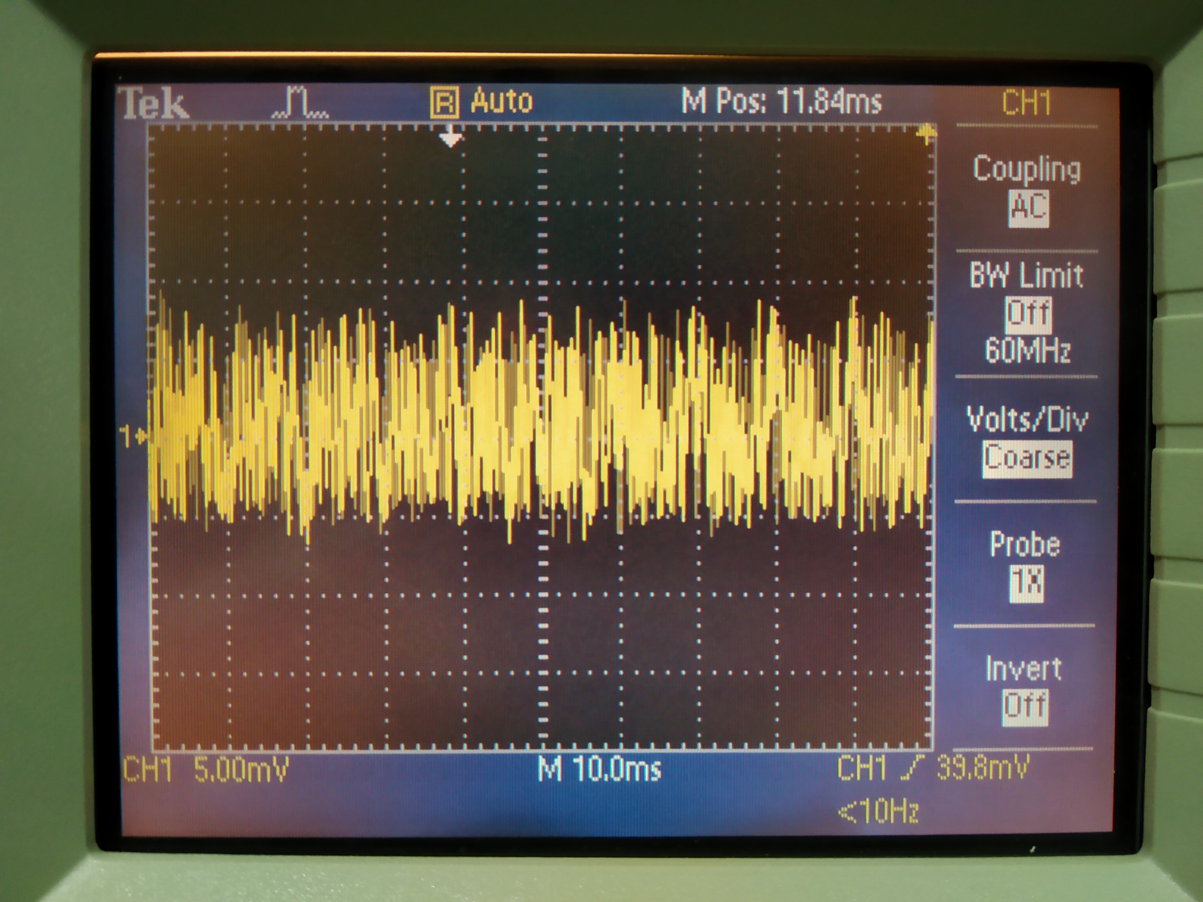
1.Beat note: (1) 20MHz Sine wave with 100Hz frequency modulation, deviation of 1MHz. (2)20MHz Sine wave with 100Hz frequency modulation, deviation of 1kHz. (see attached figure 1 and 2)
2. Local oscillator: 20MHz from DDS board.
The purpose of using these two signals is to check how PLL acts when we have a "beat note" signal deviating from local oscillator. The result is as following:
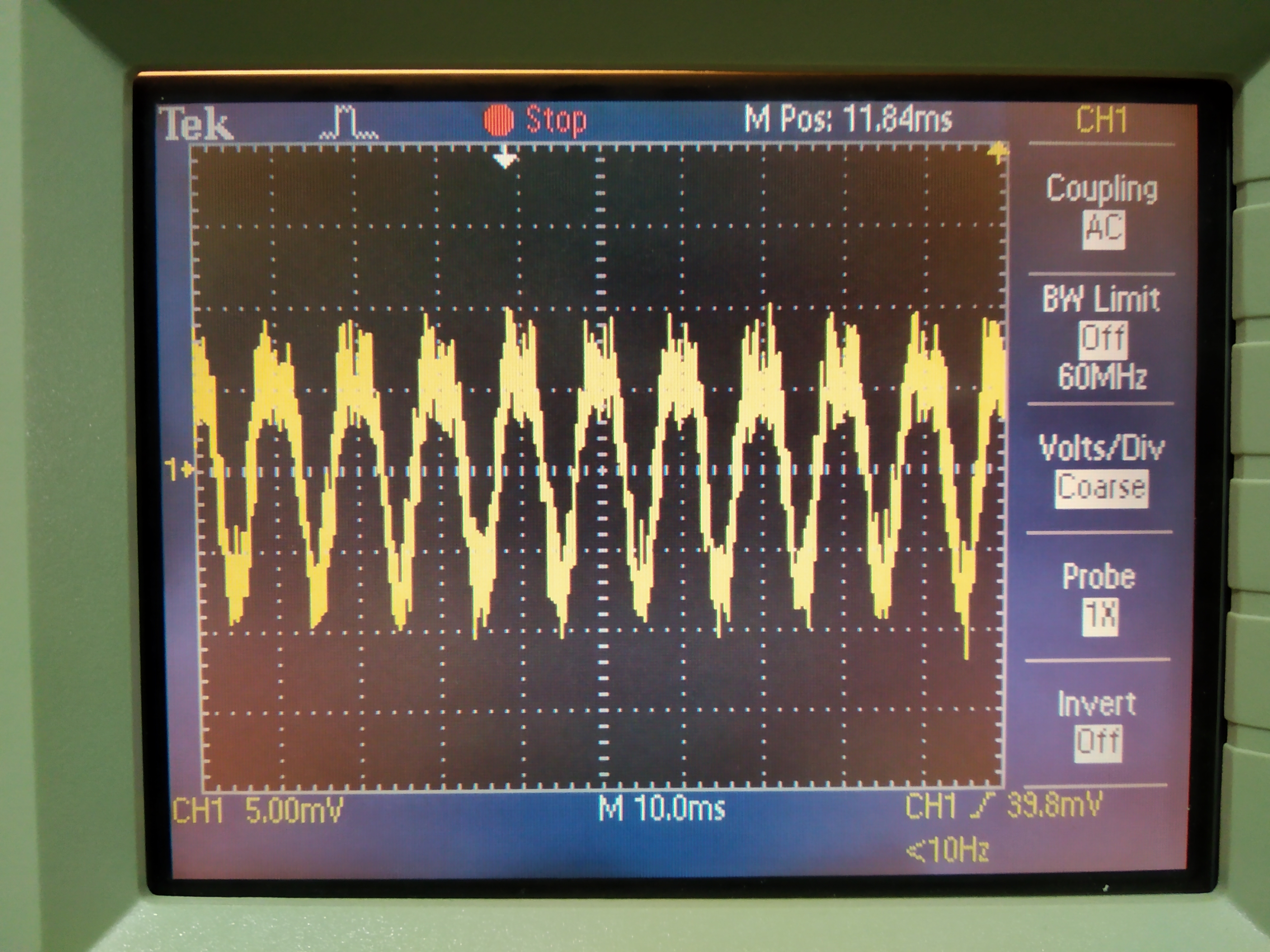
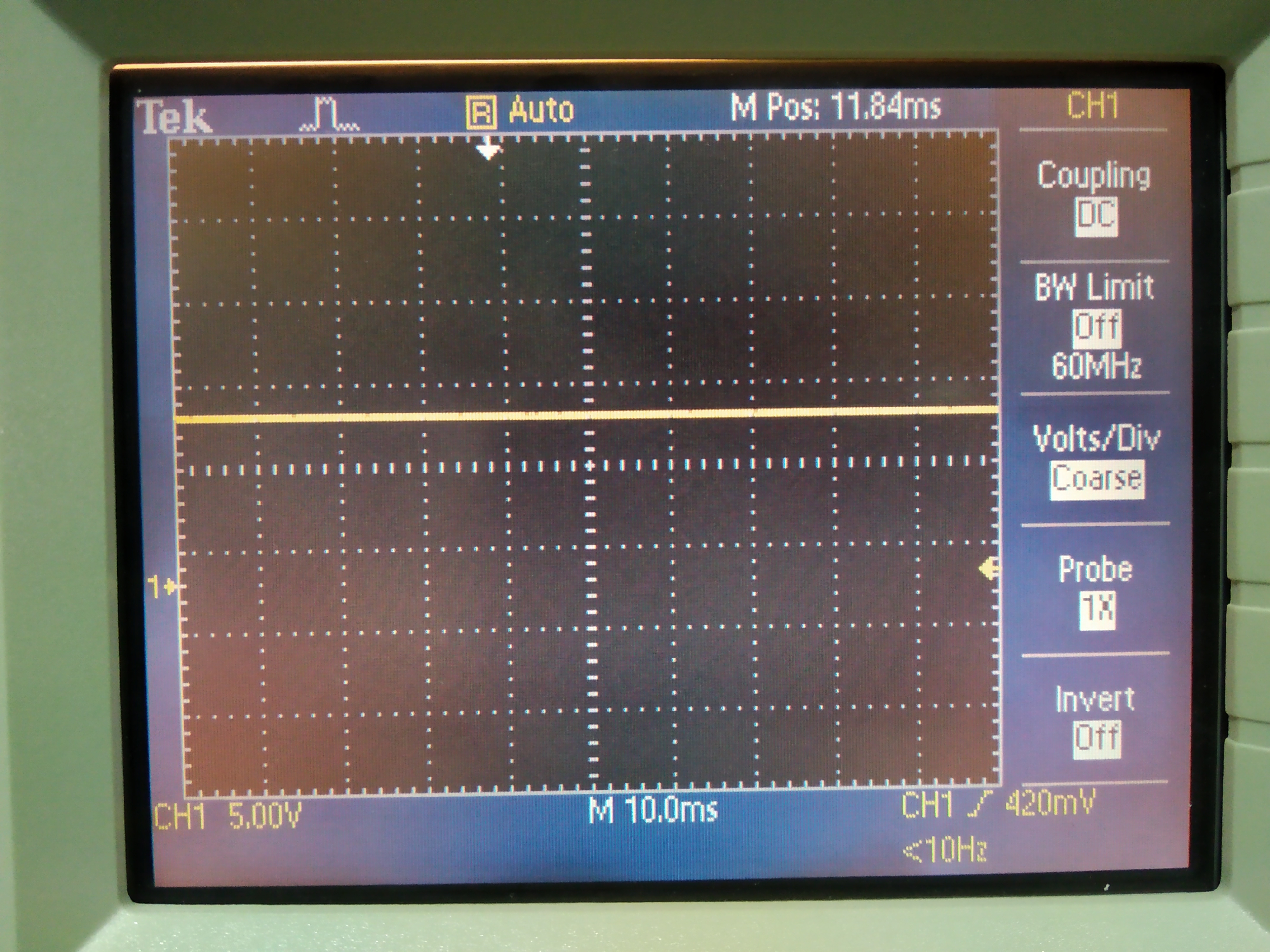
1. Close the fast control loop. Sending beat note (1) and local oscillator. We check on oscilloscope and found it almost give just an offset of 10V. If we look at the AC of this signal, there is something(20mV) and the frequency is 100Hz. So it is sensing the difference between LO and BEAT.(see attached figure 3 and 4)
2. Open the fast control loop. Others are the same with rsult 1. We found almost nothing. So this means the small AC signal we get is because of the comparison of LO and BEAT.
3. We also tried to reduce the deviation. Close the loop and send beat note (2) and local oscillator. Then we got an AC signal without a clear frequency.
Conclusion: The PLL board has a problem. Actually we did the same test when Chienming was here. At that time, the signal we get from output channel is quite large.
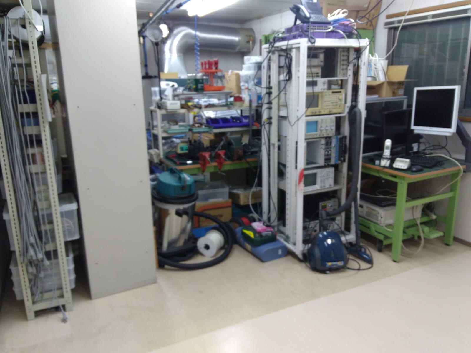
Last Monday, the damaged part of the floor of TAMA circuit prefab (a.k.a elecshop) has been repaired.
In order to allow for the floor replacement we moved away everything in the interested area and we took the chance to do some cleaning.
We will put everything back in the next days and possibly tidy up a bit.
local oscillator amplitude 16dBm(DDS3 CH0)
beat note amplitude (p pol-main laser before amplification) is -7dBm
beat note amplitude (s pol-main laser before amplification) is -10dBm