NAOJ GW Elog Logbook 3.2

Takahashi, Yuhang, Eleonora
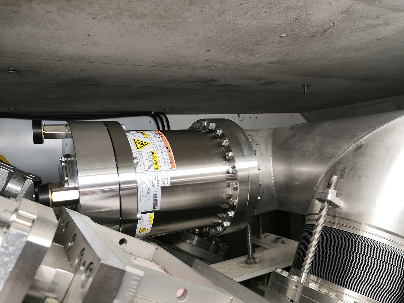
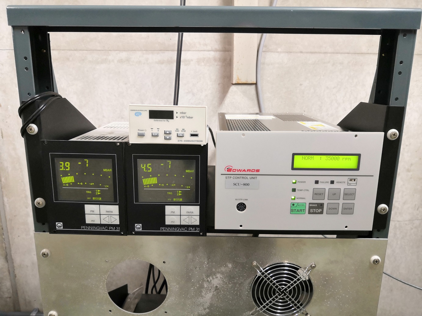
We replaced the TMP near NM2 from TMC1000MC (broken) to STP-1003 (new).
- Removed the screws for the ICF253 flange. Dismounted the old TMP.
- Mounted the new TMP. Set the rotational direction of exhaust to 225deg. Fastened the screws for the ICF253 flange. Final torque was 250kgf/cm.
- Connected the dry pump (DSP250). Started the dry pump. Opened the angle valve.
- Turned on the controller. It showed a fail due to different combination between the TMP and the controller. Reset the controller, then the controller went to auto tuning.
- Started the TMP. The TMP went to normal operation.
- After monitoring for two hours, opened gate valves to the 300-m pipe. The pressure became 4x10⁻⁷mbar.
Yuhang, Eleonora
During the "ADC trouble" we found out that PR oplev PSD was not working fine:
- SUM channel was giving a negative output
- Y channel doesn't respond to vertical movement of the beam position on the sensor
We replaced the PSD with a spare one.
[Note that this spare was previously used for BS oplev (see elog #1947) and we changed it as we suspestected it was noisy but after the replacement we kept oberving occasional noise floor excess in BS so we confirmed that it was not PSD fault.]
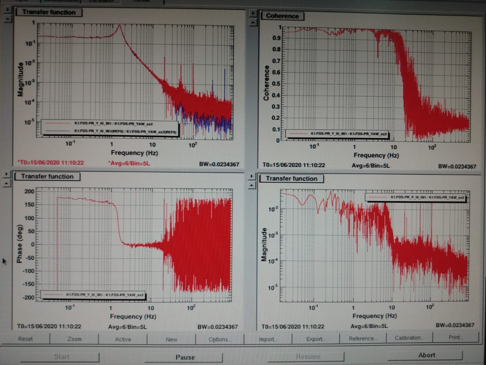
After the replacement I mesaured the TF of PR (pic1) and found that it perfeclty overlaps to the previouse one, so I didn't need to modify the gain of the damping loops.
We suspect that PSD falilure can be connected to the AA burnt card. Investingations are on-going.
Yuhang, Eleonora
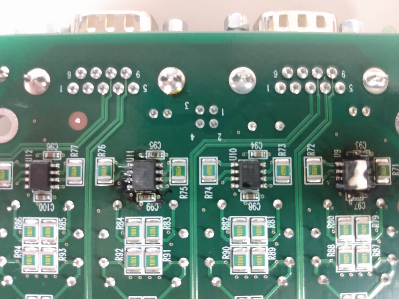
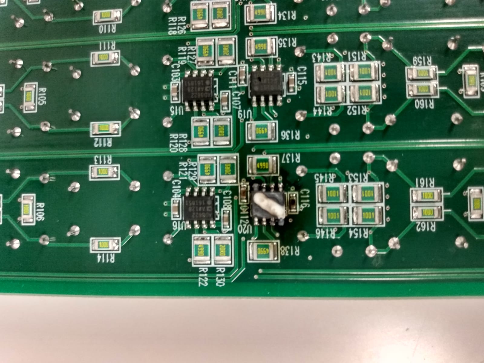
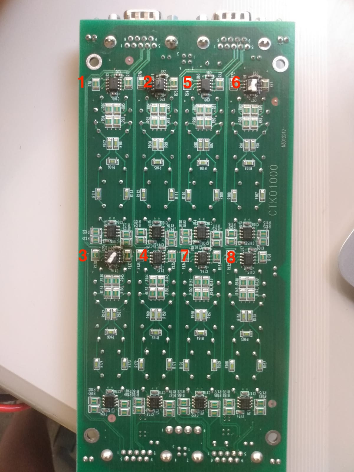
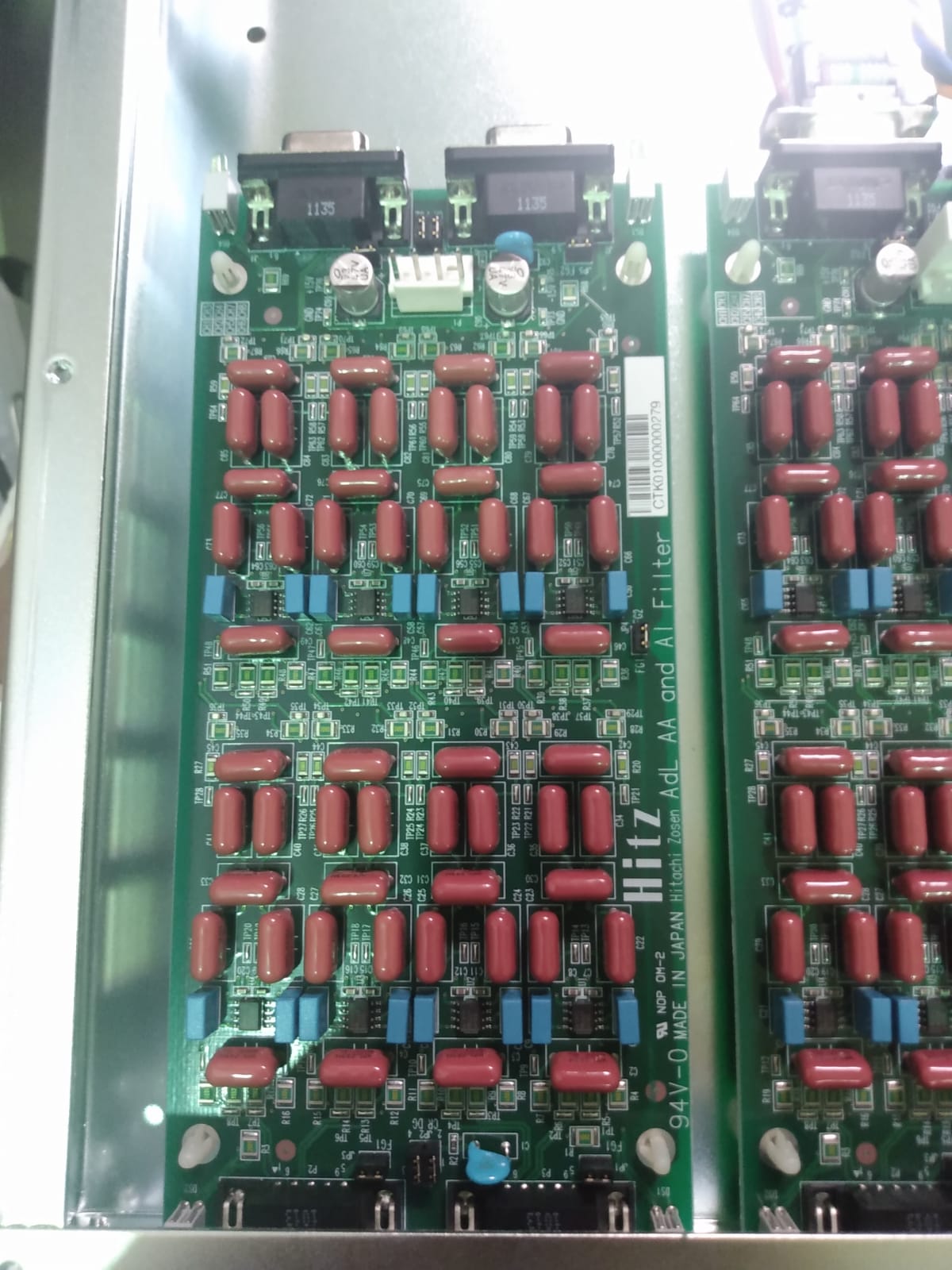
We removed the broken card from the AI module (see elog #2093) and we found that at least 3 opamp AD8622 were burnt. (see pic 1,2)
The evidently broken opamps are: (see pic 3)
CH2 -> Oplev PR X
CH3 -> Oplev PR SUM
CH6 -> Oplev BS SUM
CH3 and CH6 are the most damaged. They corresponds to the SUM of oplev PSD for PR and BS. We remark that this two PSD uses the same power supply.
We also remark that PR PSD is not working fine anymore (in particular channel Y and SUM).
We asked Miyakawa-san who said they have never had a similar problem in KAGRA.
Yuhang, Eleonora
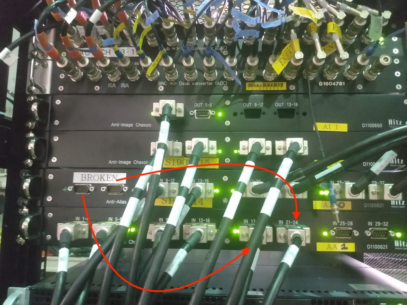
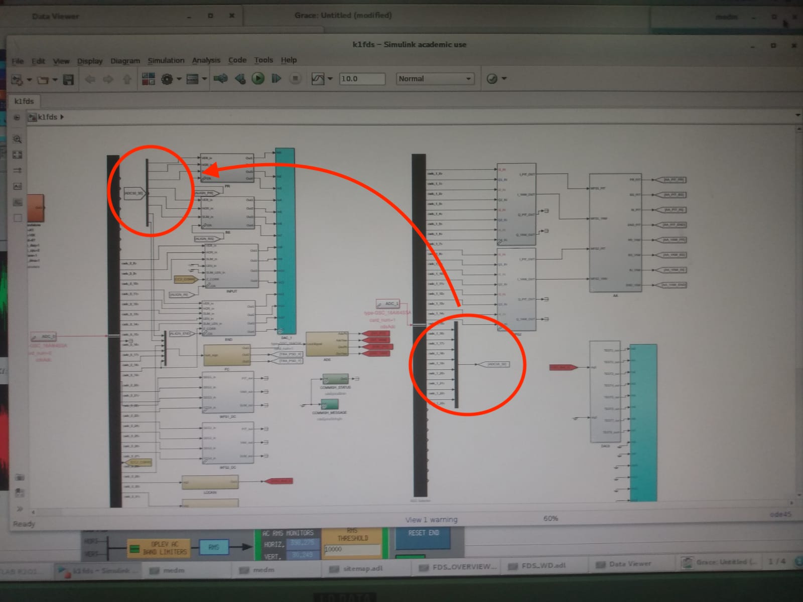
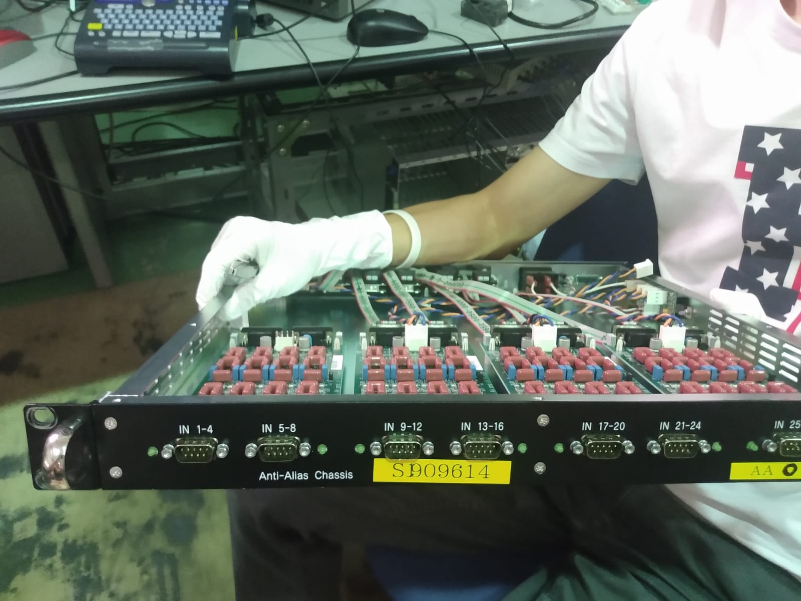
I changed the cable connection in order to move the channels that were connected to the broken AA card (AA 0 1-4 and 5-8) to a spare one in another AA module ( AA1 17-20 and 21-24). See Pic1.
I modified real time model accordingly. See pic2.
We tested the ADC input 1-8 and they are working fine now.
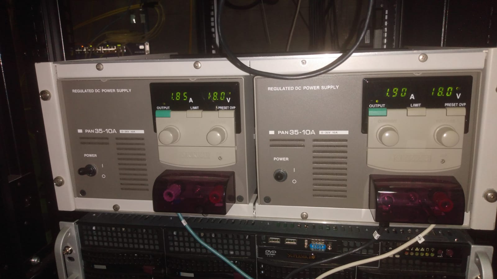
Power supply is also ok since we disconnected the broken card inside the module, two days ago. Pic 3.
While doing ADC test we realize PSD of PR Oplev has some trouble. We will investiange it later.
Yuhang, Eleonora
On Tue evening 9/06 we found out that some of the ADC channel were not working fine and one of the two power supplies was delivering the maximum current (3 A) and the saturation led was on.
I switched it off and on but after ~30 min it stated to saturated again. A strong smell of overheated plastic was present around the ADC/DAC modules. I switched it off for the night.
Yesterday after confirming that DACs were working fine we check the ADC channels one by one. Here what we found:
| 1 | 2 | 3 | 4 | 5 | 6 | 7 | 8 | 9 | 10 | 11 | 12 | 13 | 14 | 15 | 16 |
| no sign | no sign | no sign | strange |
strange |
strange | OK | OK | OK | OK |
strange |
OK | OK | OK | OK | OK |
We suspected the first card of the AI module (channel 1-8). We extracted the module form the rack and we confirmed that the first card had a very strong smell of burnt but we couldn’t individuate the broken component (we coudn't remove the card from the module to check the bottom part). We disconnected the card from the alimentation and reconnect again the AI module to the power supply. No saturation occurred since then. We will consider how to replace it.
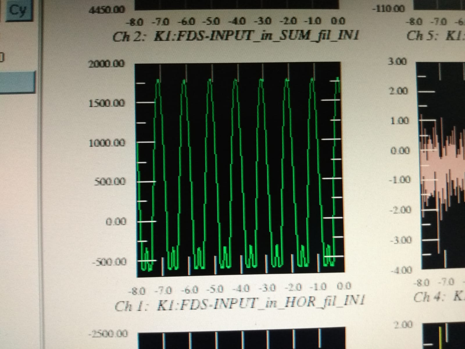
Note that ADC channel 11 even if is not connect to the broken card shows a strange feature (see pic 3). This channel is now used to acquire OPLEV INPUT SUM and it is not used in any control loop but the problem should be investigated.
Yuhang, Eleonora
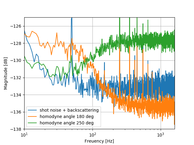
Last week we re-measured FDS with the new Faraday isolator.
The cavity was very well aligned (both in IR and green), mirror motion was small, but we could not go below shot noise at low frequency.
The squeezing at high frequency is 2.5dB (1dB less than usual). We suspect the Faraday is introducing more losses than we expected(elog 2055).
The back scattering seems quite low but we suspect that this is due to the low motion of suspended mirrors and not to the FI. In fact, in a previous measurement we observed high back scattering also with the new Faraday isolator(elog 2069).
Today I tried to lock the laser to the folded cavity with SR560 and succeeded to do that though it lasted about 10 sec.
In addition, I estimated the finesse from the linewidth of transmitted beam.
First, I measured the cavity length with a ruler and it was about 82 mm.
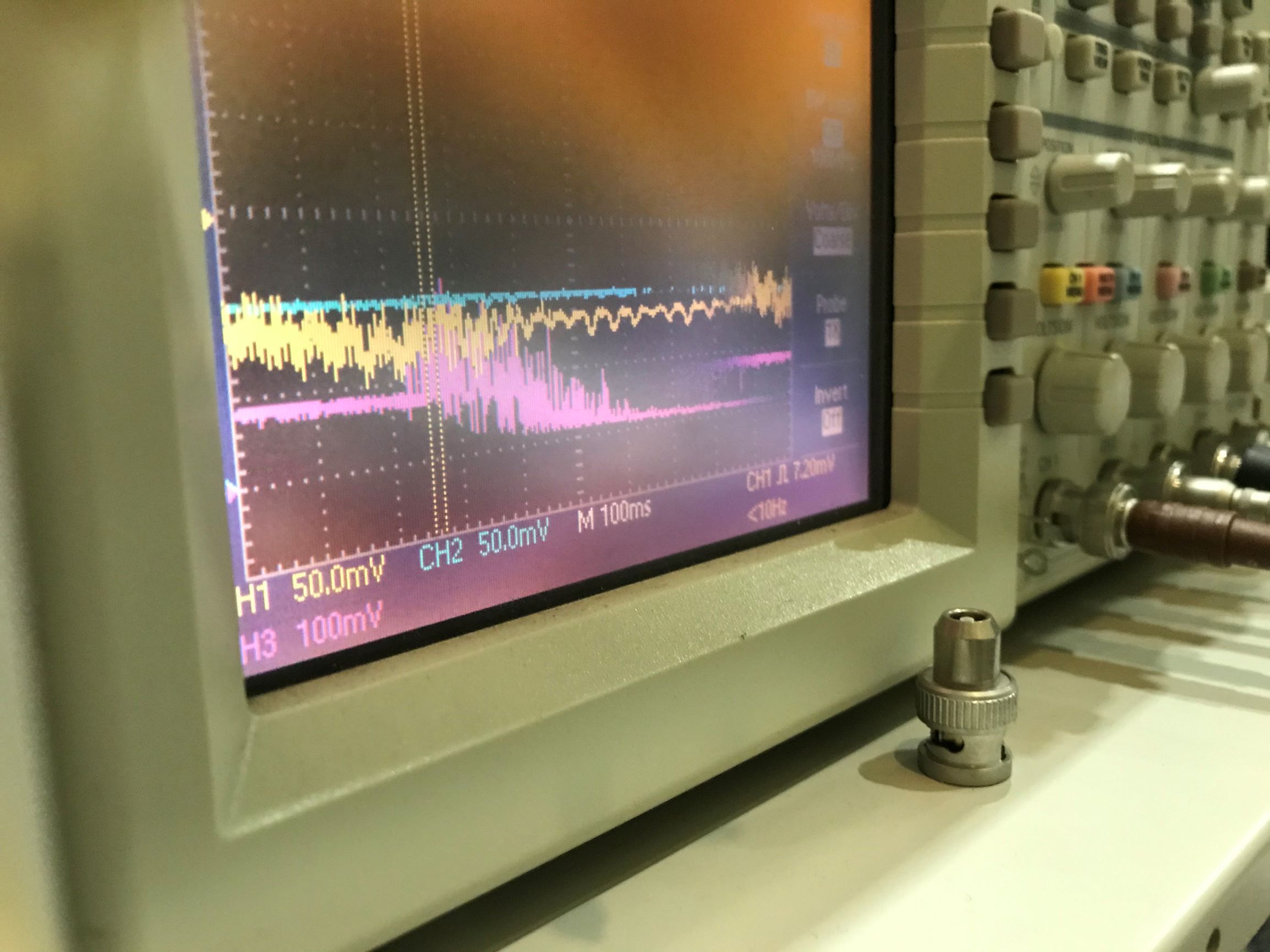
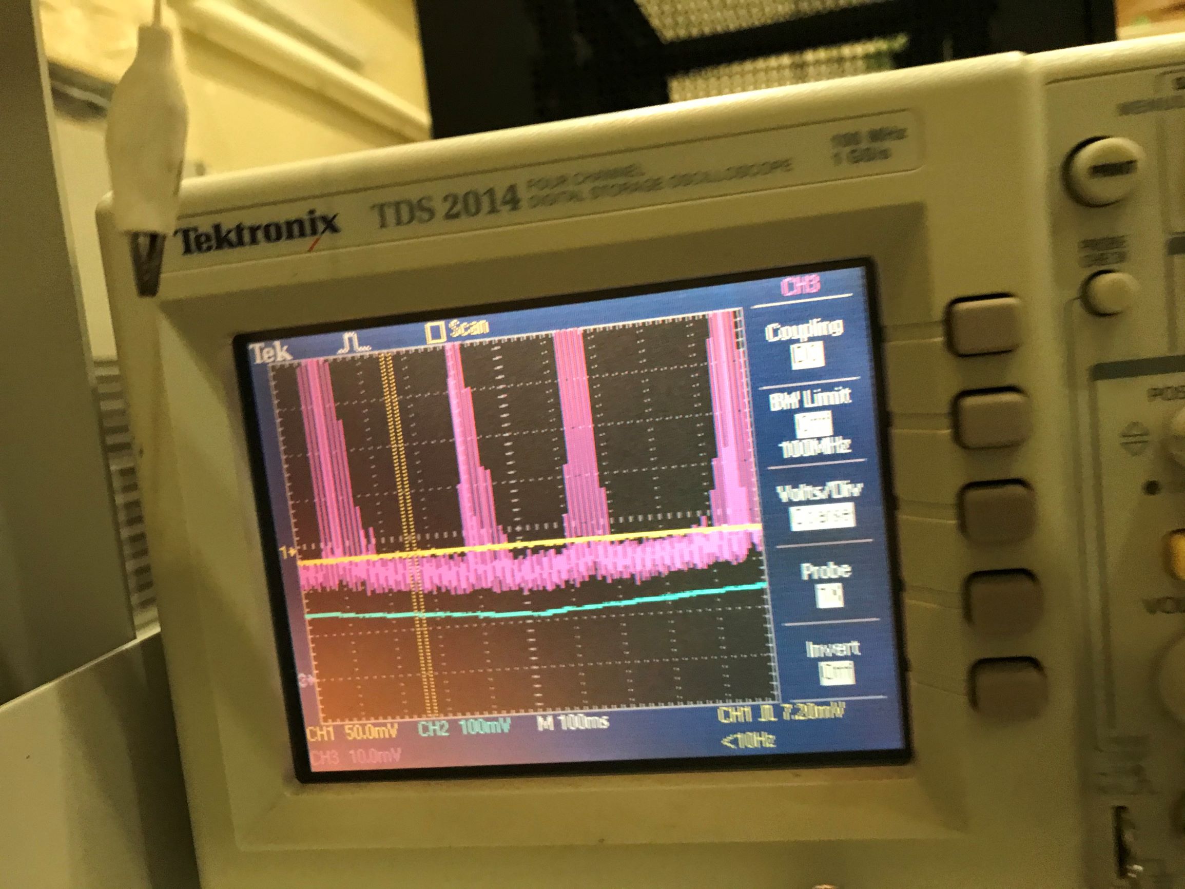
Then I scanned the laser frequency and measured the linewidth of the transmitted beam.
The free spectral range can be estimated as
f_FSR = 3e8/(2*83e-3)=1.8*109 Hz.
And the linewidth was about 1.4*105 Hz.
Therefore, the finesse can be calculated as F = 1.3*104.
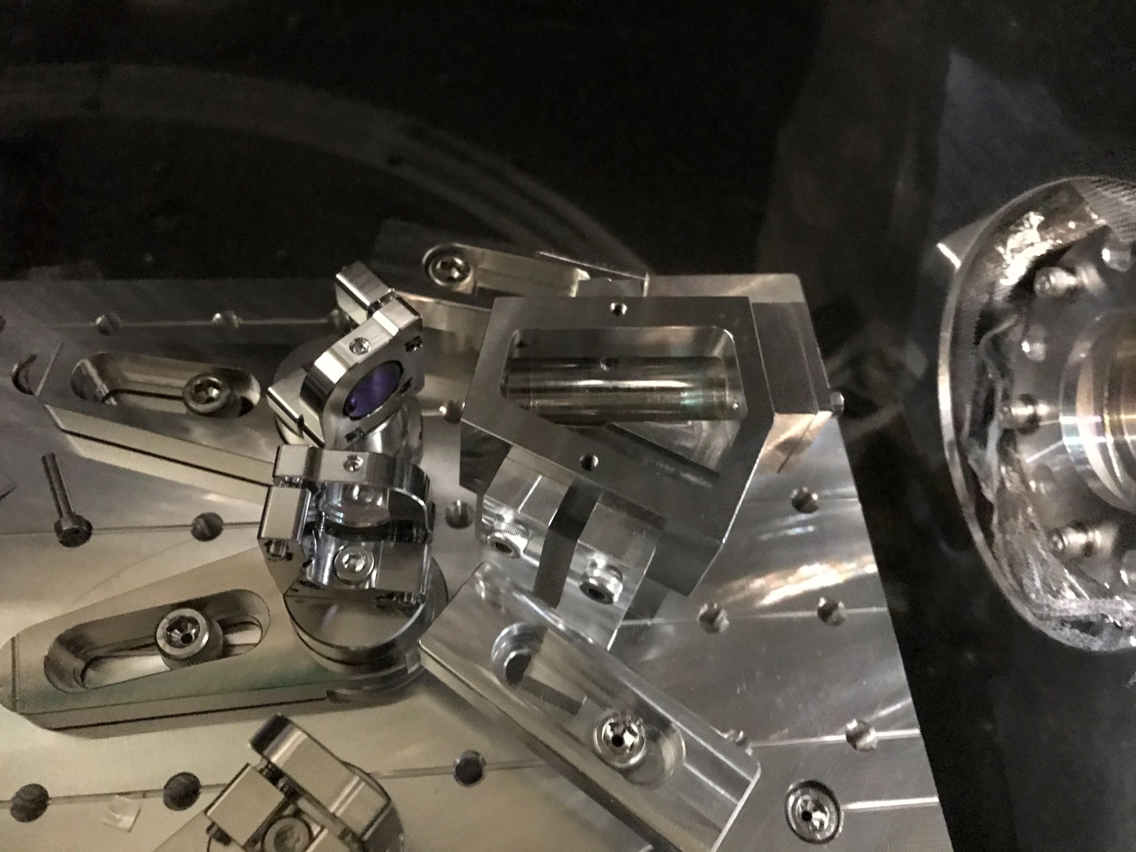
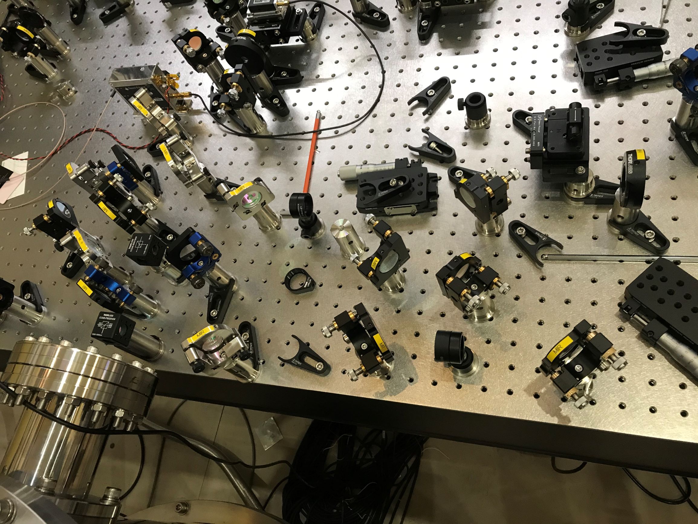
Today I tried to align a cavity with folded geometry as shown in the picture.
The cavity has asymmetric cavity length where the longer one is about 60 mm and the shorter is 15 mm.
Eventually I could see the transmitted flash as attached picture.
Therefore, it may be possible to lock the cavity with a folding mirror though I have not checked the finesse nor transmitted power.
Tomorrow I will estimate the finesse with folded geometry and try to lock the laser using the servo.

Takahashi-san, Yuhang, Eleonora
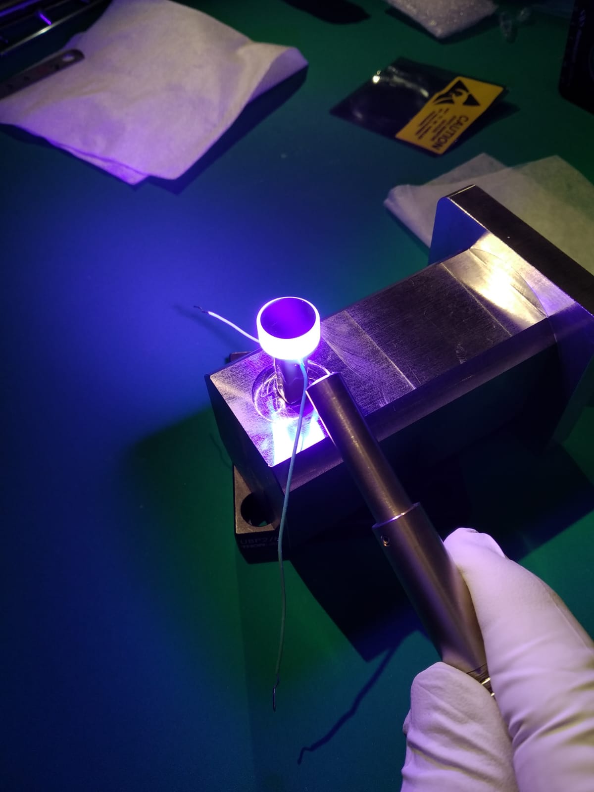
With the help of Takahashi-san we assembled the new GR phase shifter by gluing PZT and mirror on the new mount.
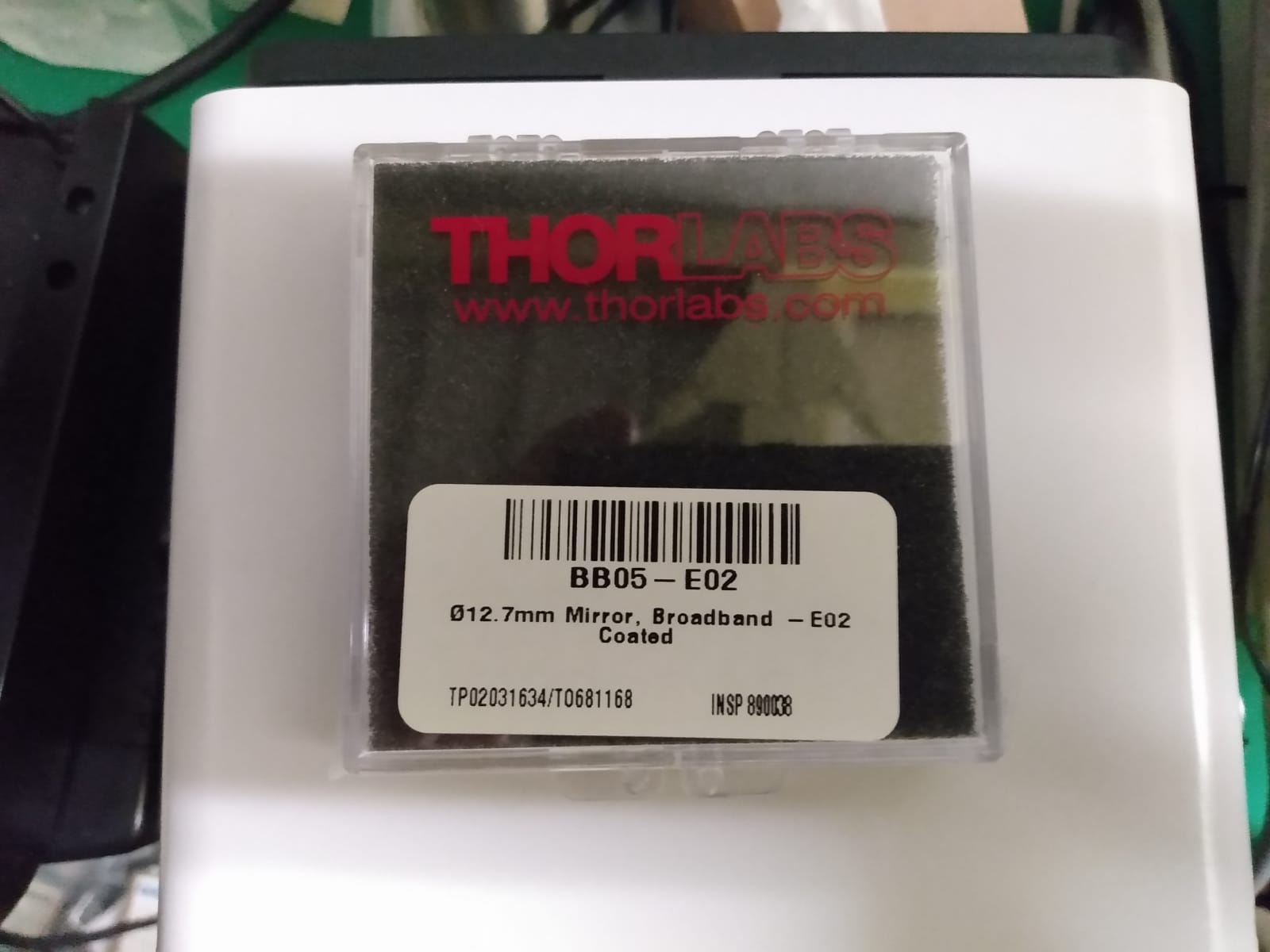
The GR mirror spec are shown in pic 1.
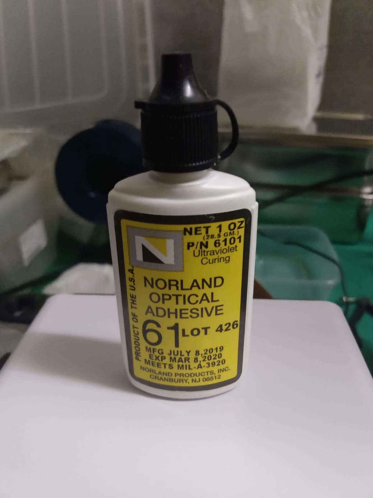
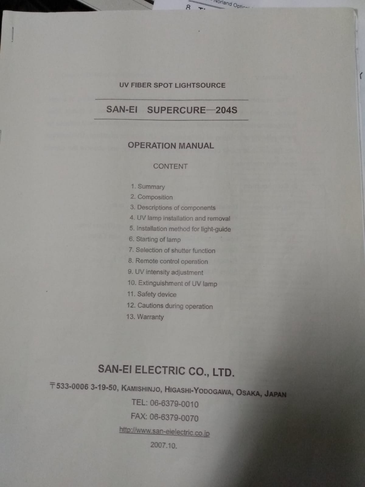
We used a glue (norland optical adhesive 61 in pic 2) that cured by 10 min exporsure to UV lamp (that lamp usually stored in 20 m lab, see manual in pic 3)
We soldered the new pzt connector(pic 5, green wire of PZT is positive) and replace the old phase shifter.
New alignment method for GRMC: since the new phase shifter doesn't have knobs to be adjusted, the alignment of GRMC now relies on the lens and one steering mirror between MZ and GRMC. Just as a memo, Yuhang moved lens position horizontally by hand. Besides, the alignment strongly depends on the voltage applied on pzt, so remember to turn on high voltage driver for green phase shifter before the lock of GRMC.
The CC1 TF (before and after replacment) is shown in pic 8. The phase noise measurement is shown in pic 6. The signal used to calibrate phase noise is shown in pic 7.
After the phase-shifter replacemnet the CC1 loop was much more stable and never got unlocked. There is 10dB attenuation for the error signal injected to the servo and the gain had to be reduced to the minimum.
This entry is log on May 28.
As I could not align the cavity with folded geometry and see the transmitted light, I decided to play with FP geometry to confirm whether the fused silica mirrors are O.K. or not.
The cavity length was set to 6.4 cm.
Actually, I could see the transmitted beam easily.
After that, I estimated the finesse by scanning the laser frequency.
The measured value was about 1.46*104 where the designed value was 1.5*104.
Therefore, the fused silica mirrors seemed to be O.K.
Next step is to lock the laser to this FP cavity and then I will try with folded cavity with shorter cavity length.
Yuhang, Eleonora
We check the power at different points on the bench and compared with nominal values. We only had to realign IRMC. After re-alignment its trasmission is above 80% (much larger than GRMC)
Here the current values for reference:
| GR power before green EOM | 280mW |
| GR power before AOM | 51 mW |
| GR power before MZ | 220mW |
| GR power after AOM | 16 mW |
| GR before GRMC | 48 mW |
| GR after GRMC | 93 mW |
| GR into the viewport | 14mW |
| GR pump before entering OPO | 19 mW |
| IR power before IRMC | 2.2mW |
| IRMC transmission | 1.8mW |
Then we adjust the setup to measure FIS. We recovered the alignment of homodyne and measured the squeezing, finding values similar as before (~ 6 dB). Plots will be updated soon. We remarked that the CC1 loop is not stable and keeps unlocking. We plan to repace soon the GR phase shifter, hoping this will impove the situation.
We also checked the alignement of BAB into FC. It was still fairly good.
Eleonora and Yuhang
Today we revovered filter cavity aligment and lock.
What we did:
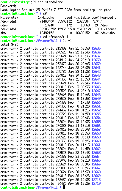
1. Erase data on the disk which was already full
2. Recover reference on BS chamber by moving last green steering mirror on bench.
3. Moving PR pitch picomotor around 300 steps (with velocity of 500) up.
4. The threshold of FC lock remote lock was wrong (maybe touched accidently by someone), we followed procedure described in elog1886 and recovered it. We found out the threshold was changed from -0.5V to around -1V. We recovered it back to -0.5V, in this case, the remote lock worked again.
5. The green transmission was around 2000 but we didn't check injected green power.
6. The air-conditioner was changed to cold mode (temperature was set to be 22 deg).
The data disk was full and diaggui and similar were not working properly.
We cheked the status and deleted some old data with the procedure reported in entry #1979.
See attached the current situation of stored data.
Simon, Pengbo
we finished the birefringence characterization of the shinkosha s5, as can be seen from the attachment(the first four figures are the result this time , the last two figures are the results last year.), it seems the offset is even larger than before.
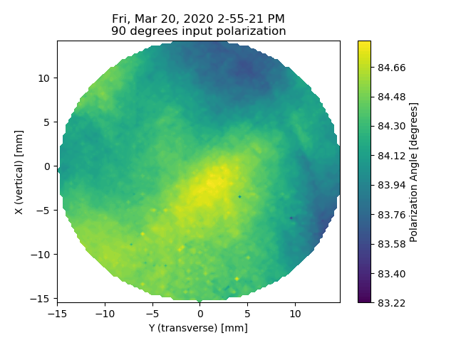
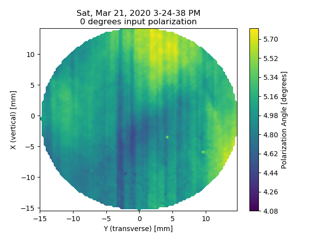
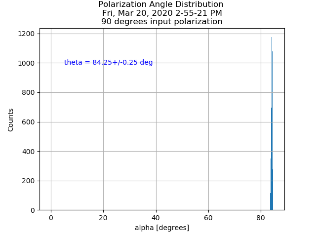
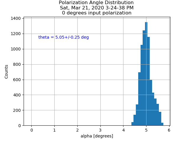
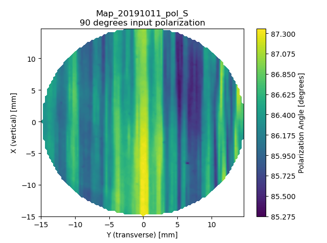
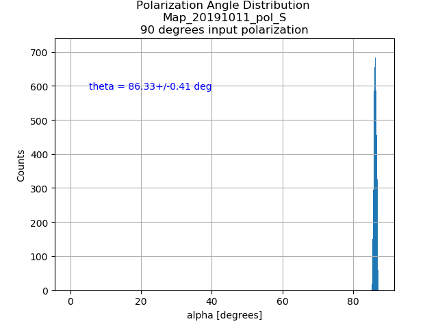
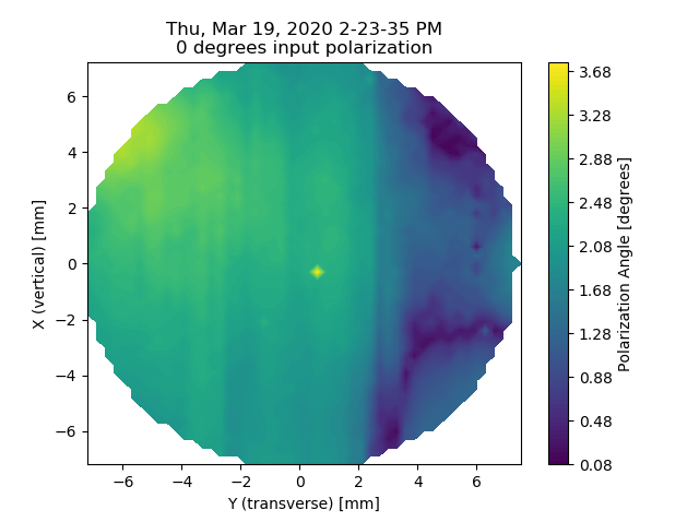
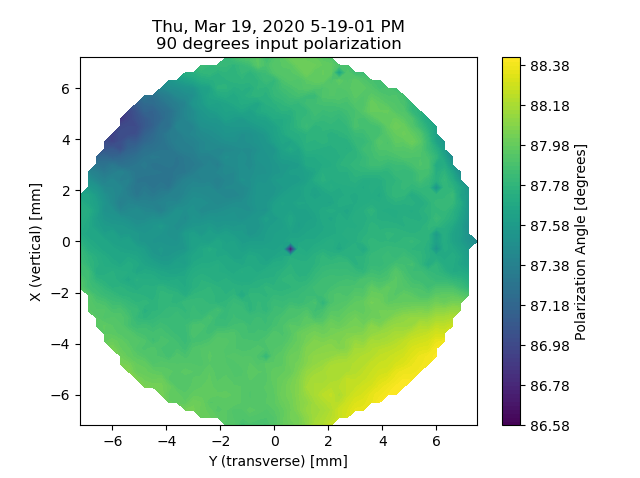
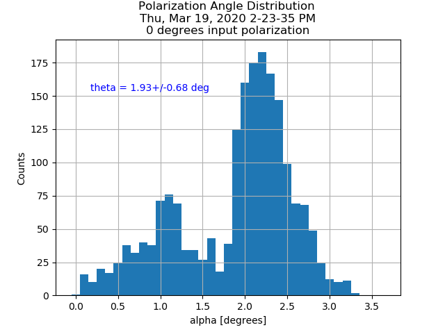
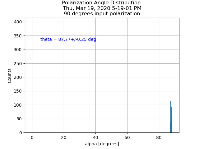
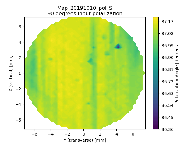
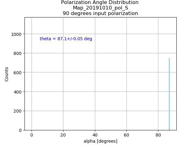
Simon, Pengbo
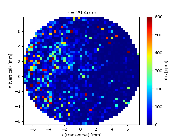
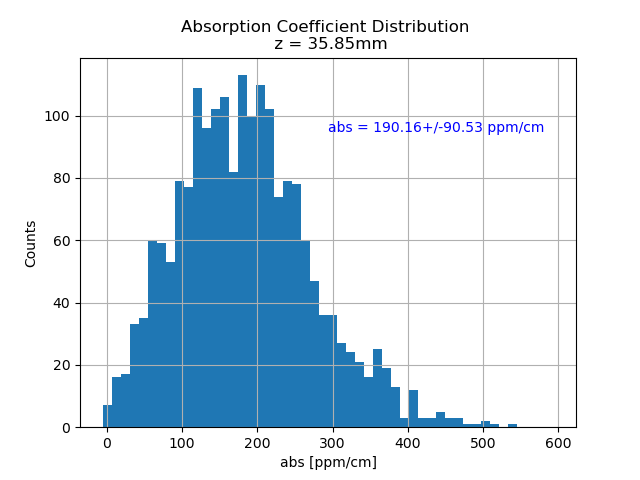
Today we finished the charaterization of the birefringence properties on Shinkosha S1 substrate. For the s-pol, we got 87.77 +/- 0.25 deg, which is slightly better than last year's result, 87.1+/- 0.05 deg. For the p-pol, we got 1.93+/- 0.68 deg, because we didn't do this measurment last year, there are no comparision. From the maps, it seems this time the distribution is more homogenous.
Here the absorption map of the second surface.
The cryostat was pumped down againg and the pressure became less than 10-3 Pa.
This level is enough for the measurement at room temperature.
So I vented the chamber and opened in order to do the alignment of the cavity.
Background
Since I modified the mode matching lenses, I had to also modify the beam path.
Furthermore, in order to avoid putting the mode matching lenses between the steering mirrors, the layout should be reconsidered.
What I Did
I determied positions of input optics around the viewport.
They are a littele bit complicated as shown in the attached picture due to the limited space.
Then I aligned the mirrors in TEM00 path.
Next Step
- Alignment of the TEM00 path.
- Alignment of the input and output fused silica mirrors.
- Need to purchase some mirror holders and pedestals for the HOM's paths (next FY).
Pengbo, Simon
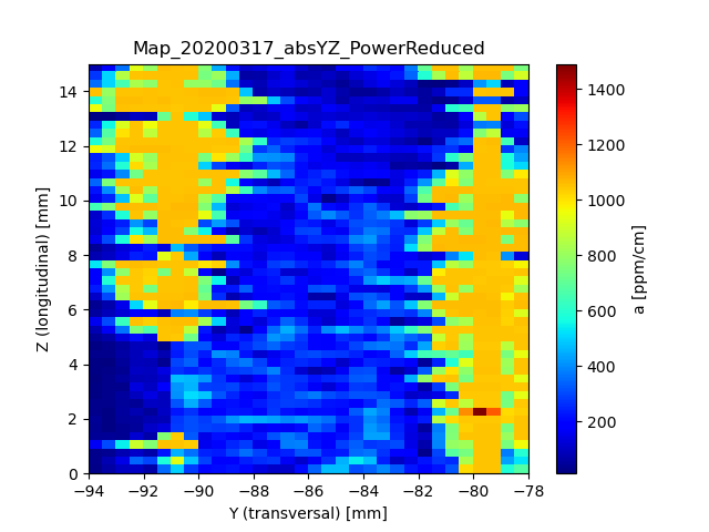
Yesterday and today we repeated basically the measurements we did on S5 for S1. The results can be seen in the attachement.
Also for this one, it became obvious that there is a large absorption excess on the surface, This time, however, it seems that this excess is existent on both surfaces. Therefore, I had run the surface-absorption measurements on both (as the time I write this, the second one did not yet finish).
The center-map shows a distribution which is somewhat comparable to the measurements we did last year. However, the mean absorption coefficient has been increased by a factor of ~2.
The next step will be to do the birefringence measurements on both samples.
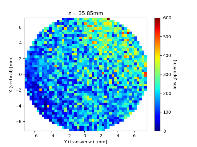
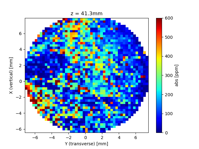
Here the absorption map of the second surface.
Preface
As the viewport attached the cryostat was not AR coated at the wavelength of 1550 nm but 1064 nm, there was a 10% loss for beam power at 1550 nm.
So I decided to replace the viewport for 1550 nm AR coated.
The cost, however, was a little bit expensive.
Therefore, I bought a AR coated window and a viewport without a window separately and they were supposed to be assembled.
What I did
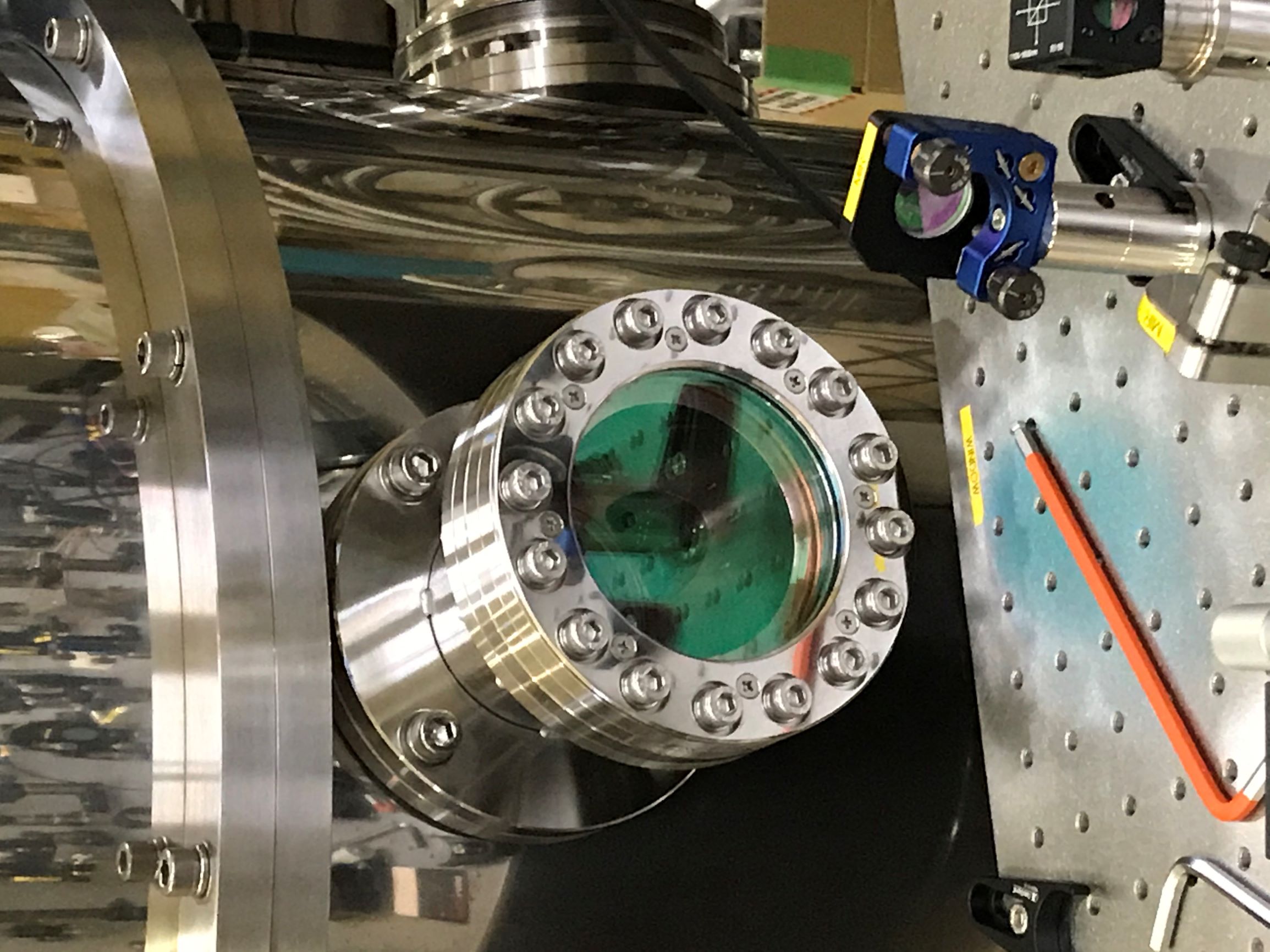
I assembled the viewport as attached pic. 1.
Then I connected to the conversion flange though I was not confident to use M8 bolts and washers stored in the ATC.
After that I installed to the chamber and vented as a test.
Before venting, I measured the beam power before the viewport and after.
Result
First, the transmitted beam power was 2.73 mW against 2.74 mW input.
So the total loss was about 0.5% which is dramatically reduced compared to the previous one.
Moreover, the viewport does not have any serious leakages and the pressure reached less than 10-2 Pa.
The cryostat was pumped down againg and the pressure became less than 10-3 Pa.
This level is enough for the measurement at room temperature.
So I vented the chamber and opened in order to do the alignment of the cavity.