NAOJ GW Elog Logbook 3.2

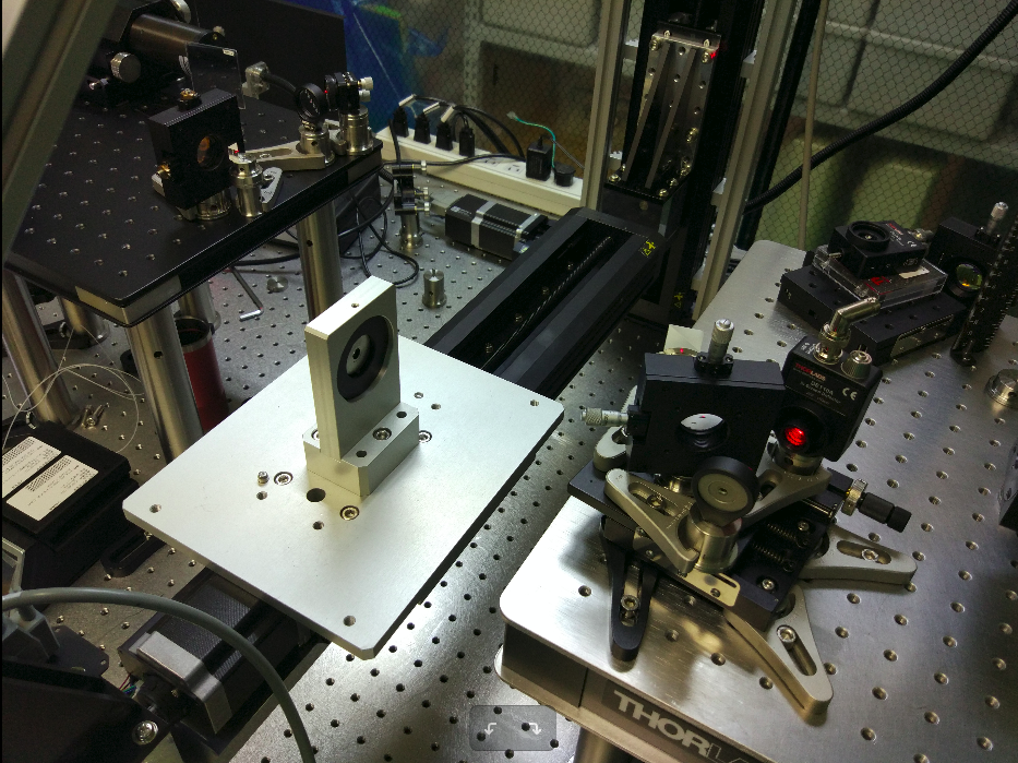
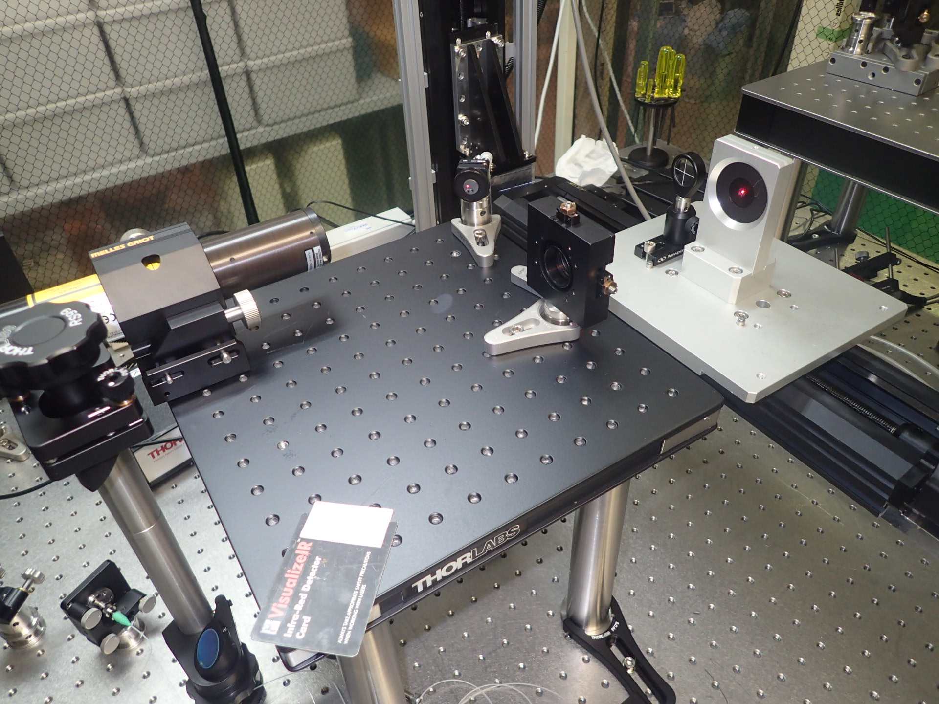
I assembled the imaging unit for the HeNe probe laser. I placed it on a 50mm translation stage.
I had to adjust a bit the position of some parts of the translation stage, sothe new pin-hole position at the cross point is
@01-axis: 2646049 2646049
@02-axis: 279284 279284
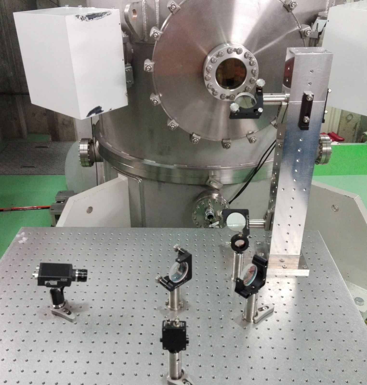
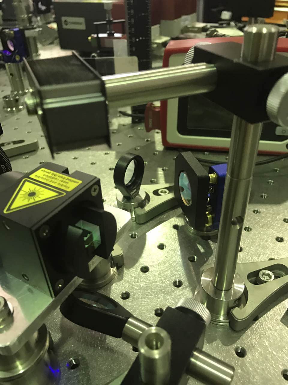
Yesterday, we finished the installation of the optical components to extract the signal from the end mirror on a photodiode and a CCD camera.
The optical bench is composed of one lens (focal length = 1m) inside the end chamber, one periscope, another lens (focal length = 0,150 m), one dichroic mirror, one beam splitter, one CCD camera and a photodiode.
Instead of using a periscope fixed on an elevated optical frame, we built a higher periscope.
On this periscope, 2 Aluminium mirrors (TFA-50-C08-10) were mounted. We also checked that they were reflective for infrared : 92,08% at 45°
The 2 lenses are used to get a smaller beam size onto the photodiode and the CCD camera. Currently, the beam hitting these two components is 6,67 times smaller that the beam hitting the end mirror. We might have to change the second lens as we expect a drastic change in the beam shape when we will remove the tube windows.
The beamsplitter will also be changed as it is supposed to be working for green (instead of infrared for the moment). It is still able to split the beam in two, so we were able to detect the beam in the photodiode and send it back to the central room.
Today I tried to measure the spectrum of the beam motion on the optical end bench, after the end mirror. The main problem is that the beam shape is pretty irregular and very elongated in the orizontal direction (almost comparable with the sensor size). In the attached plot is shown the spectrum I found for the vertical motion (both with open and closed PR and BS loops). It is just a very qualitative measurements and I'm not sure about how much it makes sense.
Some remarks
1) I used a calibration measured here for a PSD of the same kind, with red light. I'm not sure if and how it scales with the wavelenght (to be measured..)
2) The total rms (using this calibration) seems underestimating the real motion of the beam which by eye should be of the order of few millimiters.
3) The peaks are clearly coming from the PR and BS resonances. In particular the one at 10 Hz desappears when the BS pitch loop is closed as observed on BS spectrum
4) The PSD was not covered and the measurement seems affected by acustic noise.
I'll try do more quantitative measurement (better calibration, smaller beam, box on PSD) as soon as possible.

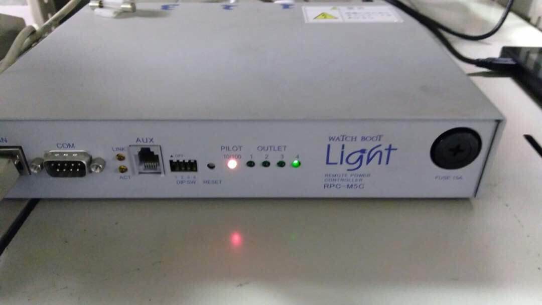
First thing is to turn the target into the remote mode, since on the label there are only two modes(remote and local), but actually when you try to move the handle, there are three levels.Remote is the one on the left.
I connected the power control box of the target (1st picture) to the '133.40.121.***'port, so when you want to control the target, you need connect to the laptop to the same IP address.
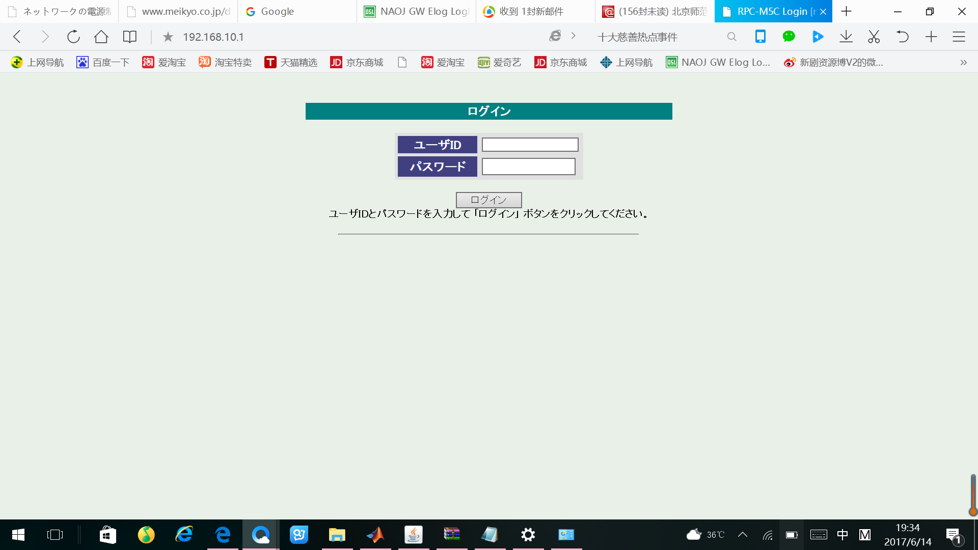
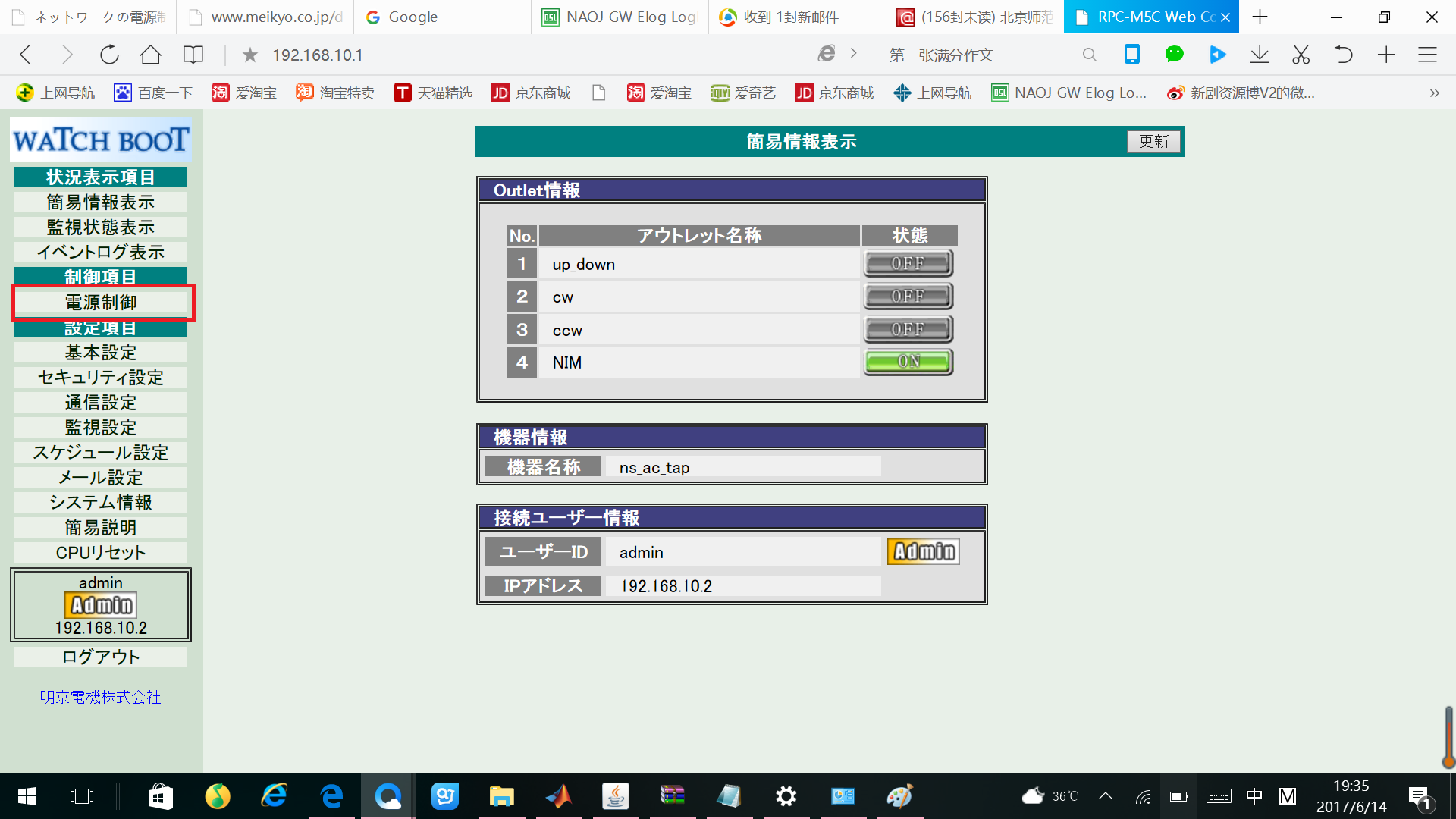
The first thing is to set the IP address and the netmask of your own laptop to 192.168.10.2 and 255.255.255.0.
Then go the address 192.168.10.1, you will see the webpage in pic 2. Enter your username(admin) and the password(magic). The next page (pic 3)shows the condition of every outlet now.
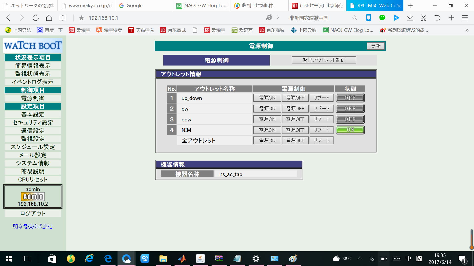
Then press the button on the left side with the red rectangle out of it, you will enter the page where you can control the power in and out.(pic 4)
Every column in the chart means:
1st: The number of the port which written on the top of the control box, from right to left is from 1 to 4.
2nd: The name of the outlet, this depend on the order you plug in everything, for now we did like what shows in the picture.
3rd: This column is used to control the power, the three buttons in each row are "power on","power off" and "reboot".
4th: The condition of the power supply now.
Since we are going to use the green beam reflect back from the end mirror to lock the cavity. We need to send the reflected beam into a PD, so we need to extract that beam out from the FI. But when we tried to do it, we found out the beam we need is reflected to the table direction, which is very hard to extract. Also the FI we are using, only the output polarizer can be turned to tune the frequency. Finally we found a way to do it, the final setup shows in the third and fourth pictures.
Today I tried to send the beam transmitted from the BS mirror out of the chamber. At first I used a one inch mirror, but the beam is almost the same size as the mirror, so it has been a little bit cut on the edge. So then I changed it into a two inch aluminium mirror. The beam is coming out from the spare window beside the tube which connected the PR chamber and the BS chamber.Then I put a aperture out side the window, center the beam on it and another beam damper after it.
There was another problem we found today. The beam looks good everywhere until it enter the tube, then when we check at the first target, it was cut.There is a bright spot in the middle and a large ring outside, the cut part is the outside part. When we tried to move the telescope mirror, the beam on the first target moved in a very strange pattern which we still cannot understand. Finally we decided to send the beam out after the BS mirror, sent into the corridor, then we checked it further but did not see either the outside part or the cut. Now we suspected that this large cut beam may come from the reflection between the target and the window. We will try to move each telescope mirror again tomorrow for better understanding the situation.

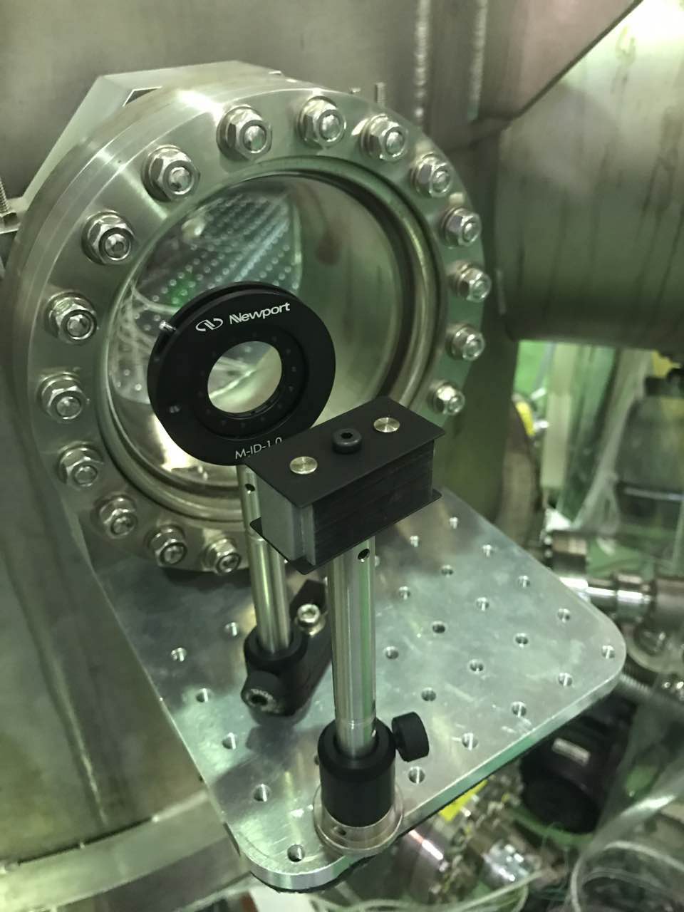

I moved the large sample to a z position such that the first surface is about 1 cm beyond the pump-probe cross point.
Using the Zaber Console, I read the position with the command "/02 0 tools storepos 1 current". Position is 1039045 1039045. Then set this position as the max translation limit for each axis with the commands "/02 1 set limit.away.pos 1039045" and "/02 2 set limit.away.pos 1039045".
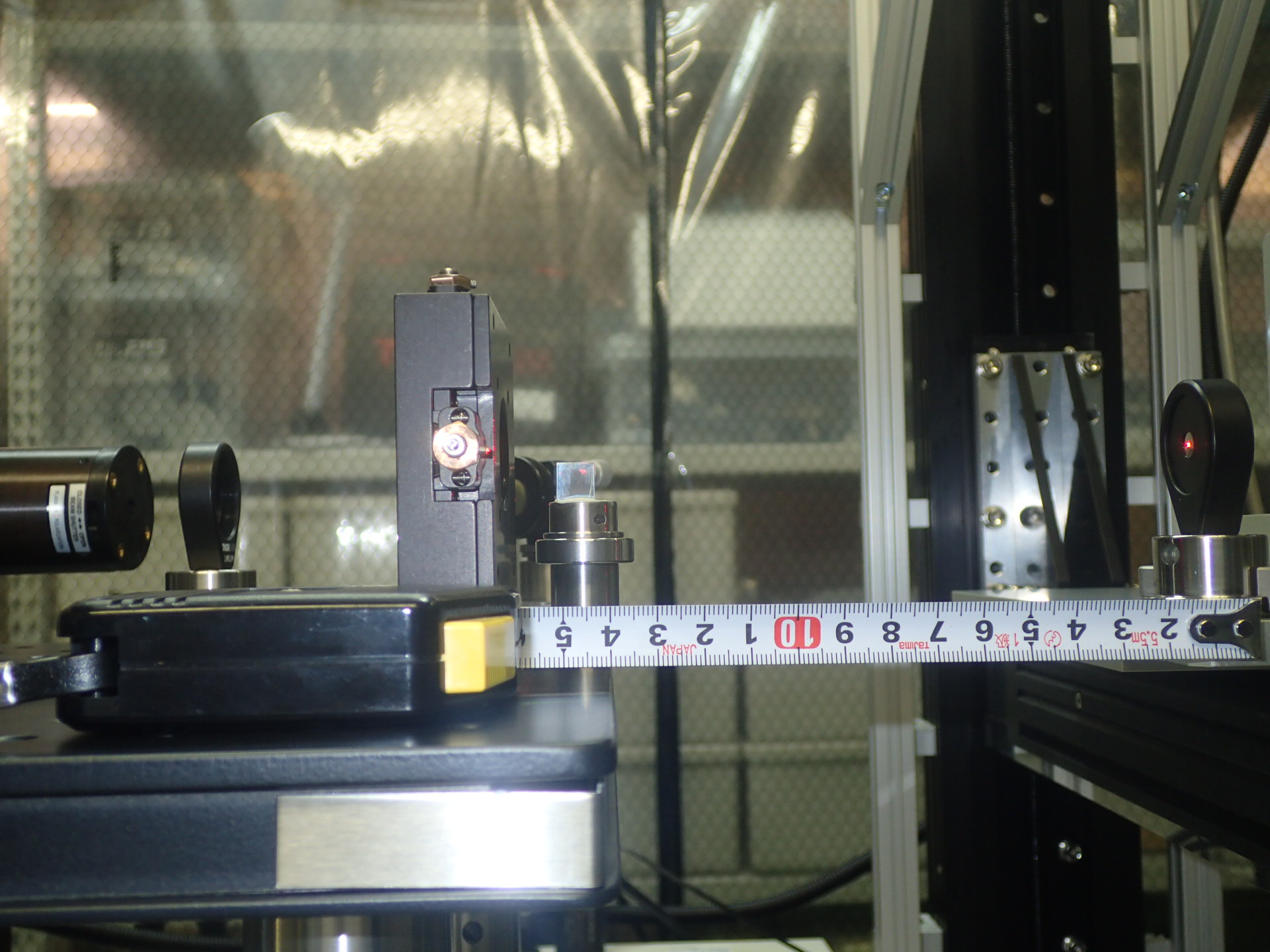
I also noticed that there is a screw of the mount that risks to hit the HeNe probe mirror mount, so I also set the min limit on axis z to 50000 steps (~6.2mm) with the commands "/02 1 set limit.home.pos 50000" and "/02 2 set limit.home.pos 50000" see picture.

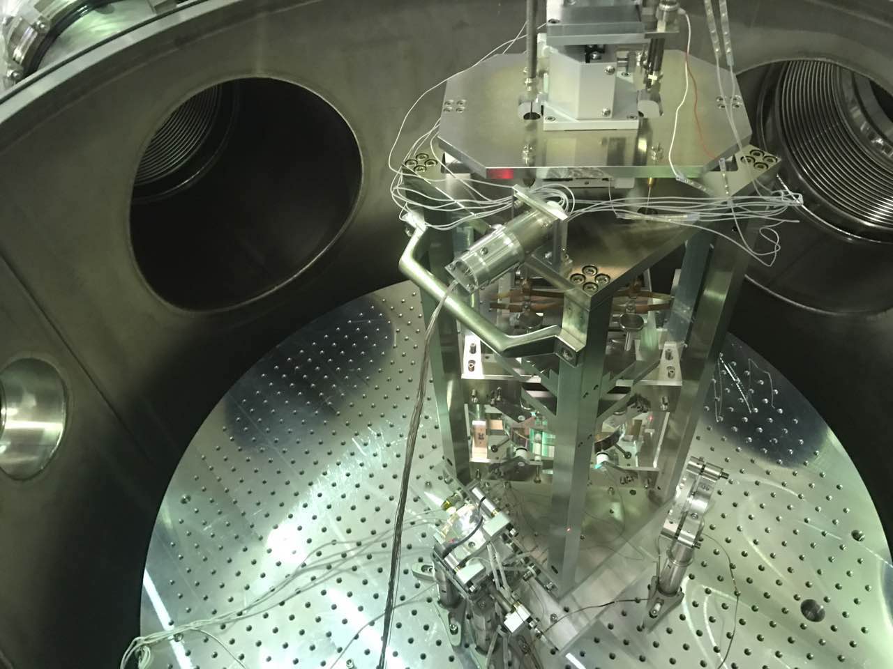
In the past days I have been working in order to restore end mirror local controls. I had a hard time finding a satisfying diagonalization both for the sensing and the driving. The current mechanical TFs, openloop TF and the comparison between open loop and closed loop spectra are shown in the attached pdf. See for comparison what I found for the dummy mirror last july.

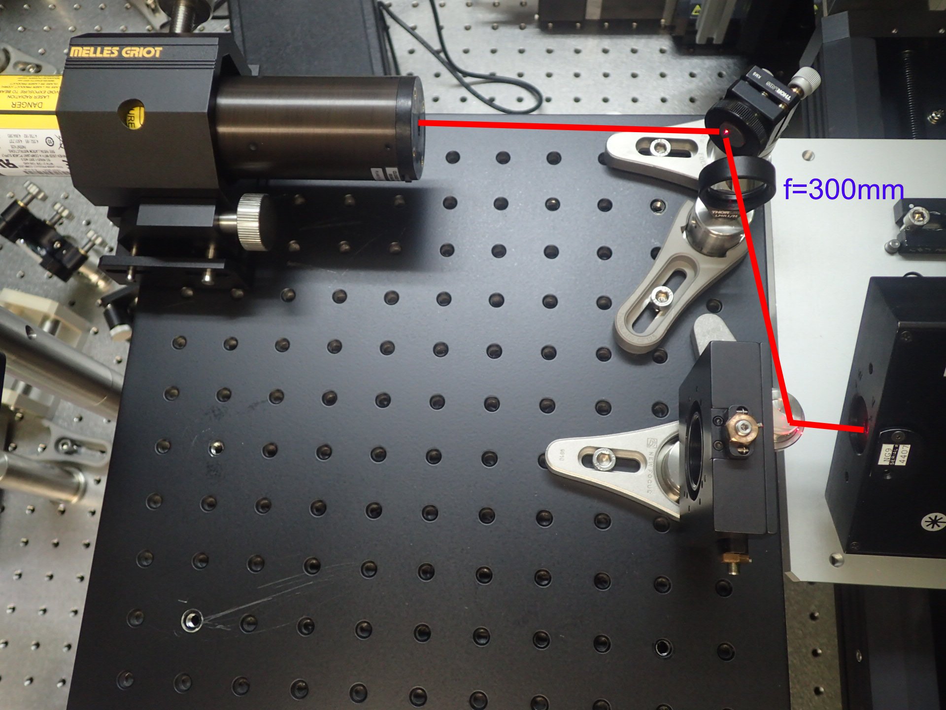
I calculated with Jammt the best position and focal length in order to have a probe waist of 180um at the cross point. So I replaced the lens with a f=300mm lens and measured again the profile. Then I plot the pump and probe profiles together. The waists positions are aligned well, within 1cm to the crosspoint. Next step is to align the imaging unit and maximize the absorption signal of a reference sample adjusting the pump position.
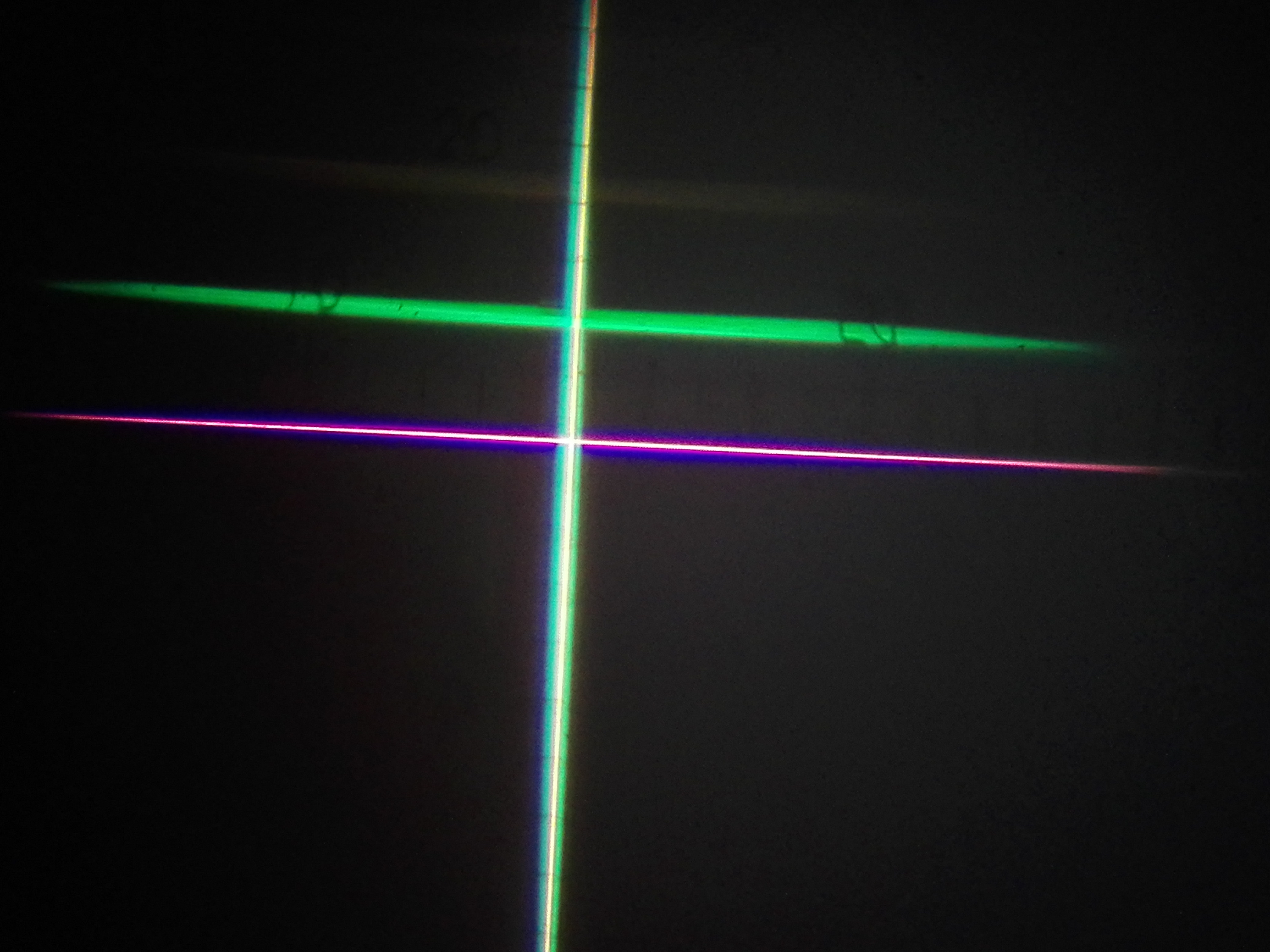
I used a 200um-diam pinhole to set the position of the crosspoint between the pump and the HeNe probe ().
First I checked the position of the pump waist, by looking for the position of the maximum transmitted power through the pinhole. I found 185mW/206mW at 11.9cm +/- 0.5cm (14cm from the board) which is consistent with the previous measurement with the beam profiler and fit.
Then, using a crosshair, with the help of Matteo, I aligned the HeNe laser to be at 0.1rad (5.7deg) with the pump beam and passing through the crosspoint at 14cm from the board.
I mounted the pinhole to the 2inches mount using the 1inch-to-2inch adaptor. I centered the pinhole at the crosspoint and checked the absolute position in microsteps (1mm = 8063steps):
@1-axis 2641973
@2-axis 279284
@3-axis 981325
Then I made a fine adjustment of the probe position to maximize the transmission through the pinhole.
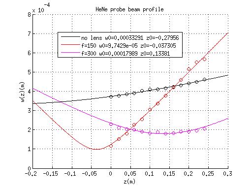
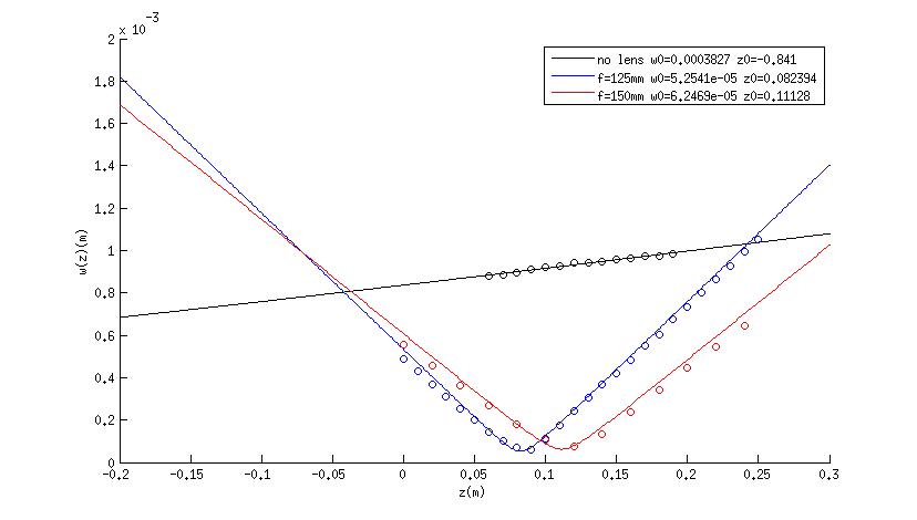
I measured the beam profile of the HeNe laser without focusing lenses and with a f=150mm lens. See plot. The waist of the probe should be at the cross point (14cm from the board). There are two ways to move the probe waist: or move the lens, or change the lens focal length.


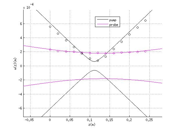
I calculated with Jammt the best position and focal length in order to have a probe waist of 180um at the cross point. So I replaced the lens with a f=300mm lens and measured again the profile. Then I plot the pump and probe profiles together. The waists positions are aligned well, within 1cm to the crosspoint. Next step is to align the imaging unit and maximize the absorption signal of a reference sample adjusting the pump position.
I had to adjust a bit the position of some parts of the translation stage, sothe new pin-hole position at the cross point is
@01-axis: 2646049 2646049
@02-axis: 279284 279284
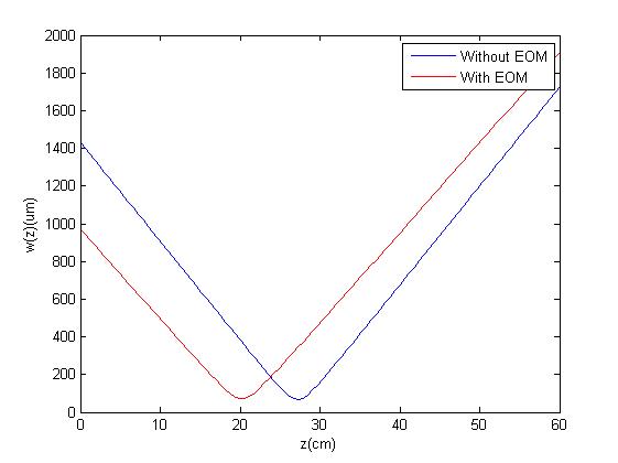
Then the beam size changed a lot at the PR window and also it seems diverge very quickly after the BS suspension. We checked the manual of the EOM, did not find anything about this situation. For better understanding what happened to the beam after the EOM, we removed the third lens, take a few measurement before the EOM and after the EOM. Then did the fitting to check what changes. The origin set as the line of hole near the second lens. From the figure it seems only the beam waist shift from 27.2 to 20.2, the beam waist size changed a bit, but we should consider that the space is limited, so we need to take several points of measurement which is quiet close to each other. Also the z value is measured with meters which is not very precise. It seems this problem can be solved only with moving the third lens.
I replaced the 125mm lens with a 150mm lens. So the waist moved as expected to 0.11m. See the plot
This video shows the movement of the green beam on the target at 290 m when the local control loops of the suspended injection mirrors (PR and BS) are closed. It seems to me that it is moving too much in the vertical direction.
In the attached pdf there are the spectra of the PR and BS mirrors.
When the loops are closed, there is still a narrow peak at about 7.5 Hz in the pitch of the PR, that is cleary visible also looking at the loop error signal in time domain. According to what observed here, I would say that it is due to the intermediate mass touching the magnet holder plate. In the past we observed that it happened often after moving a lot the yaw picomotor.
We should now try to understand to what extent the beam motion is affected by this and possibly solve the problem.
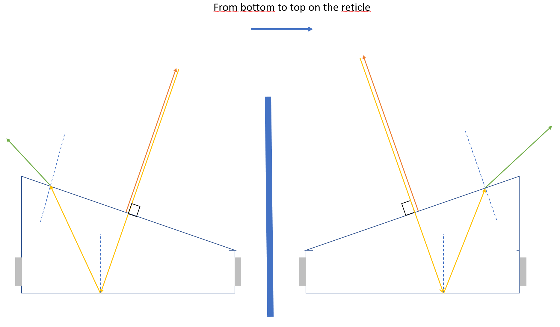
To understand which reflection was the one from the front surface, we looked at the reflections due to a roof light. When this light hitted only the front surface, its reflection was red. When it was hitting both surfaces, we could see two shifted reflections, one green and one red. So the red reflection corresponds to the front surface reflection.
The callibration of the autocollimator means that the incident beam and the front surface reflection are on the same direction. Then, depending on the wedge sign, the back surface reflection will either be seen on the top or on the bottom of the front surface reflection.
By looking at the autocollimator, we were able to tell that the wedge sign corresponds to the second configuration on the scheme. This means that the "#4" sign on the mirror corresponds to the lower part of the wedge.

In order to place the waist of the pump beam on the right position, I characterized the pump beam using the beam profiler and moving it with the translation stage.
Laser settings: I = 1A, P = 210mW , hwp_angle=0, not chopped.
I aligned the pump beam to be parallel to the z-axis translation stage within 0.2mm on the whole translation range 250mm (±0.8mrad).
The beam profiler position is set 0 at the position of the KAGRA-size sample first surface (see picture).
Without the focusing lens, the waist is 377um at -0.88m
Using the focusing lens f=125mm placed at -60mm, the waist becomes w0=53um at 0.081m
According to this calculation the deepest measurable point is 0.08*1.81=0.149m for sapphire (and less for silica). Since KAGRA-size thickness is 15cm, the cross point (which will be at the pump waist) cannot go beyond the second surface. There is not enough space to place the lens closer to the sample, therefore I need to change the focal lens.
Making a quick simulation with JamMt, a focal lens of 150mm will move the waist to 0.111m (w0=62.8um) without sample, With a 15cm-thick sapphire substrate the waist will move to 0.178m, and with a 15cm-thick silica substrate, the waist moves to 0.16m, which is enough to measure the entire thickness of the sample.
I replaced the 125mm lens with a 150mm lens. So the waist moved as expected to 0.11m. See the plot

This is the new telescope parameters:(origin still at the first line of hole out of the cavity)
L1 f1=200mm z1=8cm
L2 f2=200mm z2=56.5cm
L3 f3=175cm z3=99cm
With this new telescope we had a better beam at the window of PR chamber and also before the beam goes inside the arm, the previous one produced a beam a little bit longer in horizontal direction. So we decided to go on with this configuration.
Then today after we realign everything on the bench, took some measurement to check the difference between the theoretical value and practical one is inside the tolerance or not. All the points we measured are equal or smaller than the result of the calculation. We also added the two telescope mirror inside the chamber to check if the beam in the tube has the size we want or not. At the two inch mirror we had a beam radius about 1mm which is good, and the largest size inside the arm is about 1.3cm.
The other thing we did is we measured several points on the bench after the third lens. With these data, we calculated the beam waist and simulate the propagation of beam in 300mm, but without the two telescope mirror. From the picture we can see that the beam shape on the bench can not produce astigmatism at 300m.
Today we keep investigating on the beam astigmatism. As a first thing we realign all the optics on the bench and measured the beam in different position. There results will be posted in a dedicated entry by Yuefan which has also calculated the astigamism expected at 300 m on the basis of the measuremts done on the bench. (Very small).
Then we sent the beam in the pipe and open the first windows between the BS and NM2. The change in the shape when the windows is open is shown in this video.
After that we let the beam propagate for about 30 m in the corridor and move the small telescope mirror in order to have the beam as collimated as possible. We succeded in finding a position allowing to have a beam which remains pretty small (2-3 cm) up to the end of the tunnel.
After the small telescope tuning, the beam (both with closed and open window) looks different on the 290 target. Here there is another viedo who recorded the beam during the closure of the BS-NM2 windows. The beam with open widows looks still very astigmatic while with the close window is seems aftected by diffused light and very difficult to judge.
[I have the impression than after opening the windows for the first time it becames somehow dirtier and once we close it again, it affects the beam more than it was doing before.]
Some preliminary conclusions:
1) Tuning the 2" telescope mirror position have a great impact on the beam shape at 290 m.
2) The windows seem to have a great impact on the beam shape at 290 m.
3) The beam seems well collimated and not significantly astigmatic when it propagates in the corridor.
In order to speed up the remote control of picomotors that are largely used for the beam aligment, I wrote a custum vi which avoid to inserting each time command lines to select drivers, motors, velocity and steps (pic 1). The vi (picocontrol.vi) is in a dedicated labview project (C:Digital/picomotor_control.lvproj)
We remark that BS yaw picomotor still doesn't work.
The final configuration for the picomotors control is
CONTROLLER 133.40.121.13
A1
- PITCH BS
- YAW BS
- empty
A2
- PITCH INPUT
- YAW INPUT
- empty
A3
- PITCH 2" TELESCOPE
- YAW 2" TELESCOPE
- LENGTH 2" TELESCOPE
CONTROLLER 133.40.121.14
A1
- PITCH PR
- YAW PR
- PITCH SM1
A2
- PITCH SM2
- YAW SM2
- YAW SM1
CONTROLLER 133.40.121.15
A1
- PITCH END
- YAW END
- empty
Where 1, 2, 3 correspondes to motor 0, motor 1 and motor 2

In the past days we have been working in order to improve the green beam shape at the end of the arm.
1) We have realigned the optics on the bench many times in order to be well centered on the optics. After adding each optics we measured the beam and propagate it far (about 5-6 m) to check if we could notice any astigmatism.
2) We have tried to be as centered as possibile in the sferical mirror of the telescope and on the two gates between BS-NM2 and NM2-PIPE
3) We have change the telescope configuration for the grean beem in order to have longer focal length whit respect to the dimension of the beam on the lenses and avoid sferical aberations as much as possible.
In this condition we are able to have a beam which looks failry circular at the input of the pipe and also on the first target but which becomes very bad when observed on the 290 target. (The main effect is elongation in the orizontal direction). This video shows what we see on the far target while scanning the orizontal direction with the BS local controls. While moving from one side to the other, at first we can observe some scattered light, than we don't see anything for a while and finally we see the beam on the target. Continuing the scan, the beam disapears and after another moment of darkness we can see again the scatterd light. From this I would say that what we observe is the direct beam and not its reflection on the pipe wall.
In order to better understand the evolution of the propagating beam we have put two steering mirrors at the level of the input mirror in order to send the beam in the corridor. (As steering mirrors we used to 5" mirrors used as PR ans END dummy mirrors, which should be both former TAMA PR mirrors with long RoC )
The beam at 300 m is shown in picure. It is moving a lot because of the air but it doesn't look elongated in the orizontal direction. There are no evident reasons why the beams propagating in the corridor and in the vacuum look so different. Here some hypothesis:
1) The air is affecting the propagation, masking the astigmatism observed in vacuum.
2) The steering mirrors are not flat enough and they modifiy the beam masking the astigmatism.
3) The astigmatism is introduced by the window at the input of the pipe and becomes evident only after a long propagation (on the target at 10 m the beam stil looks good)
4) Effect due to possible multiple reflections from the target and the input window (it could be ruled out by looking at the beam reaching the end chamber)
We remark that the beam on the target observed by the camera looks better than in reality. The same is true for the pictures taken to the green beam where small deviation from the circular shape are difficult to be apprieciated.
