NAOJ GW Elog Logbook 3.2

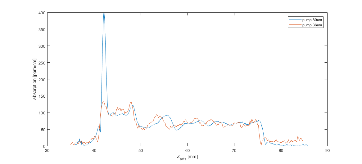
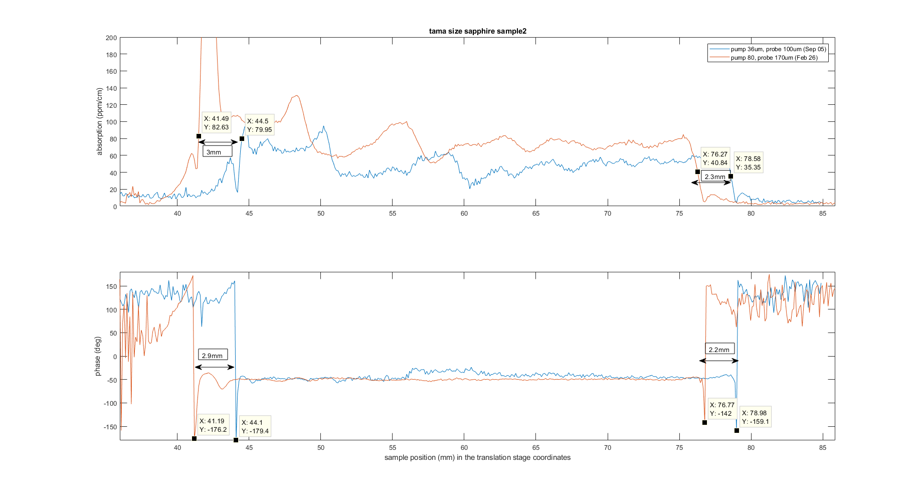
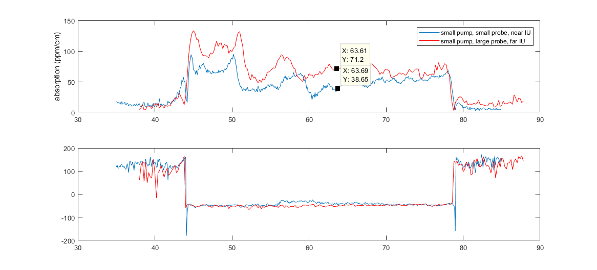
The scans in the comparison reported in elog entry 973 were shifted to make the comparison more clear, but if we plot the original data together (see first plot), we see that the crossing point has shifted after we changed the probe size and pump size.
The shift is between 2.3mm and 3mm, therefore to compare a measurement with the map taken at 50mm (reported in elog entry 678 ) I took a map at 53mm and another one at 52.5mm.
I calculate the ratio between the large beams maps and the small beams maps. See last plot
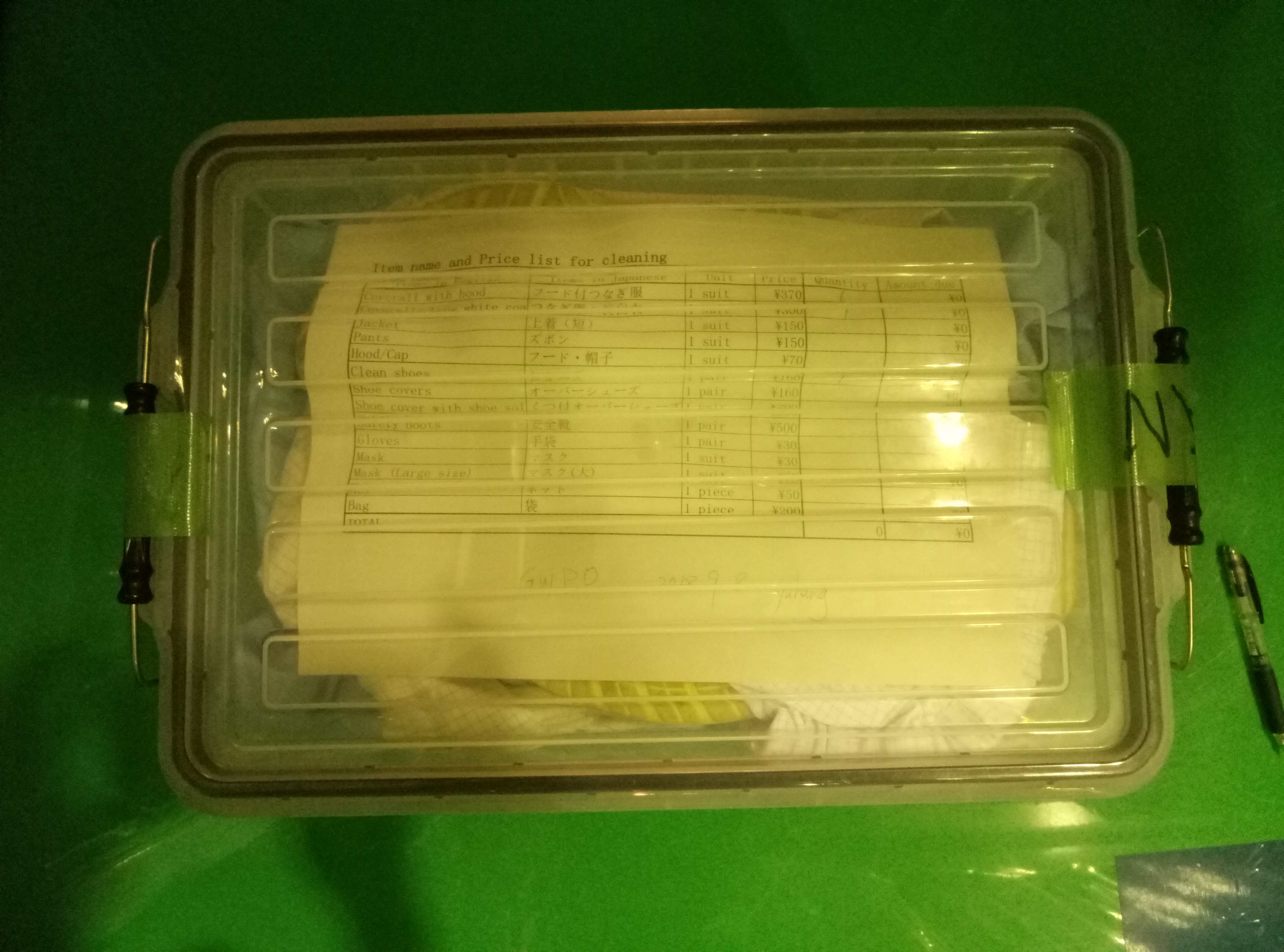
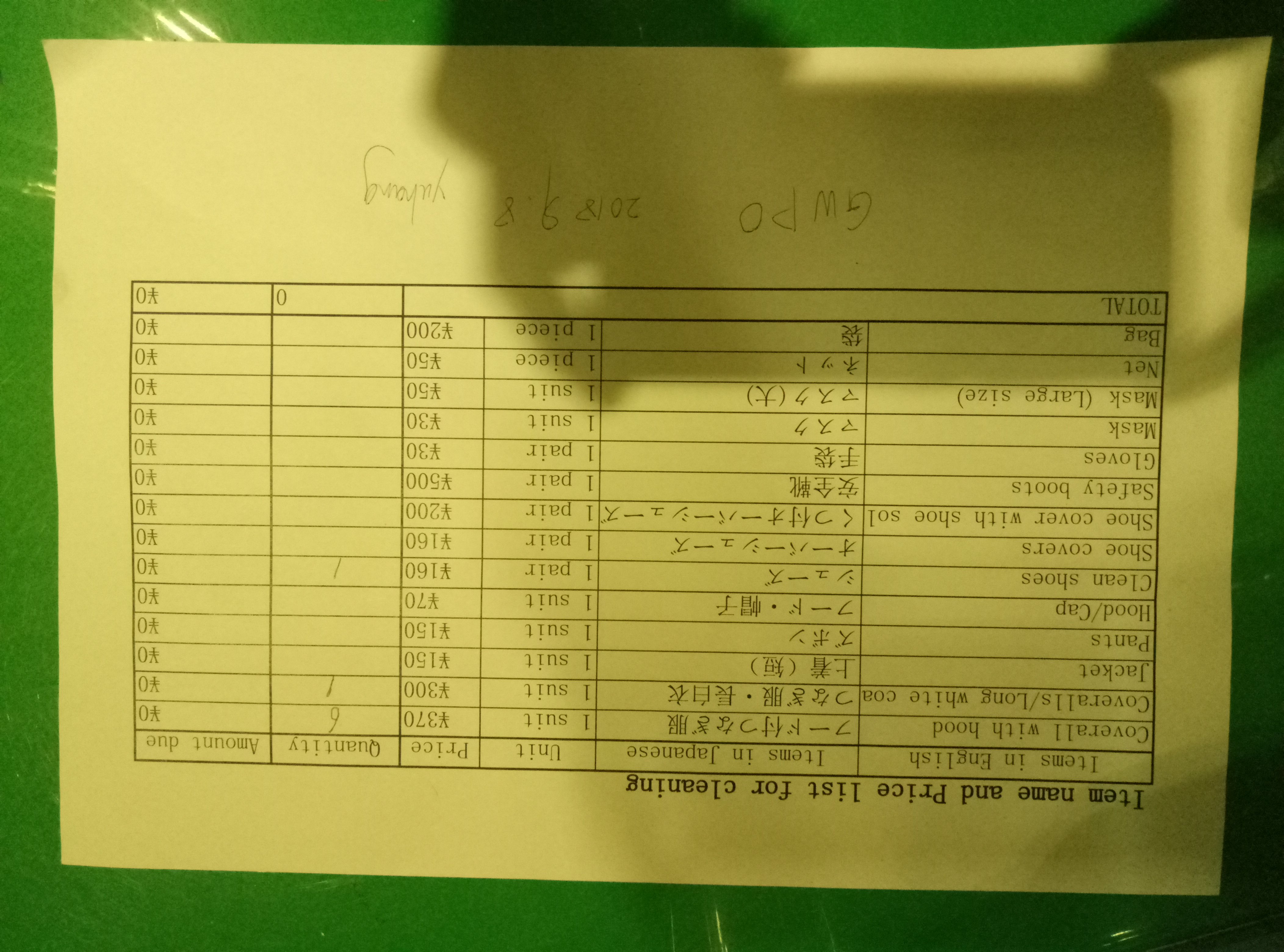
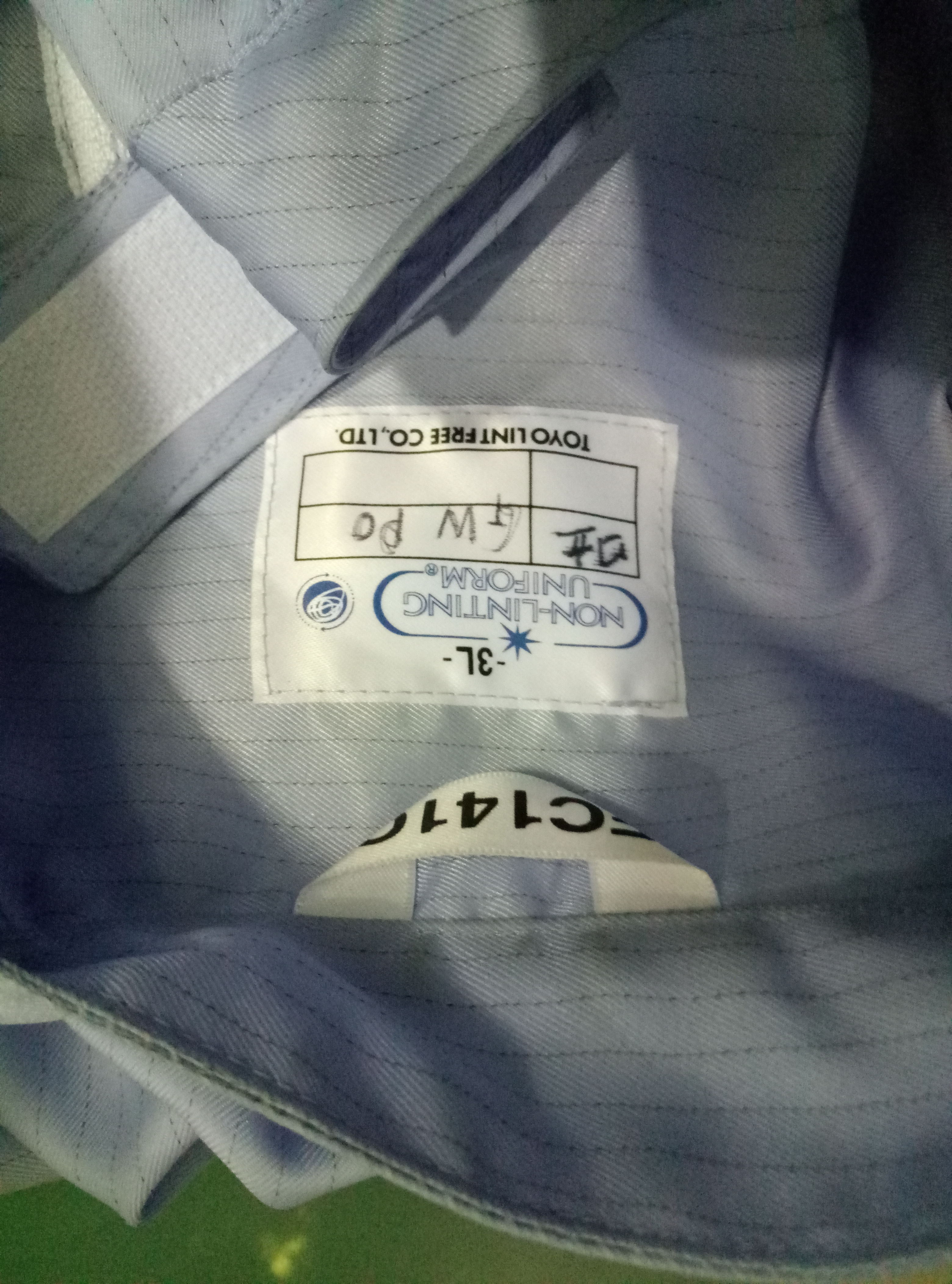
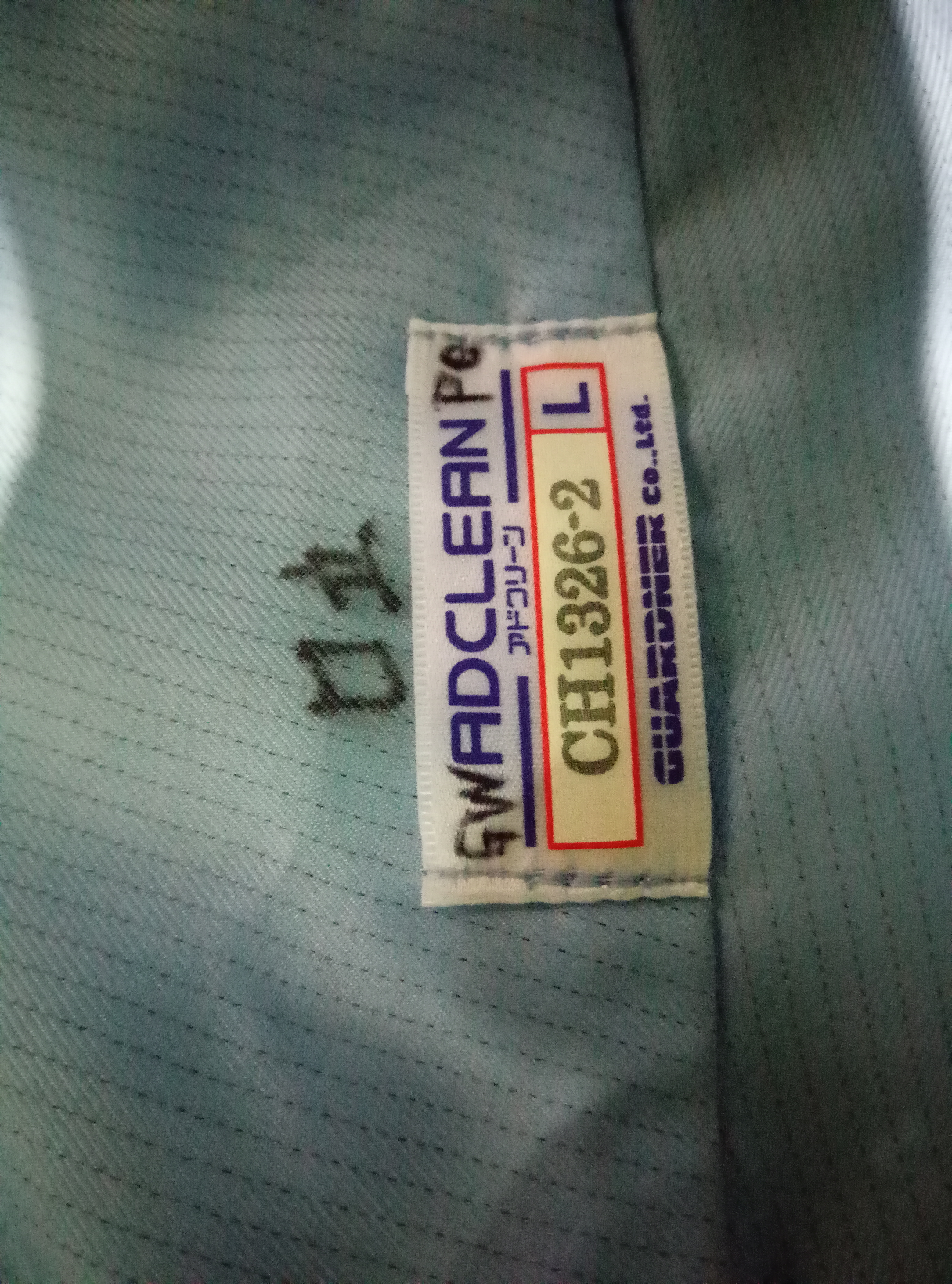
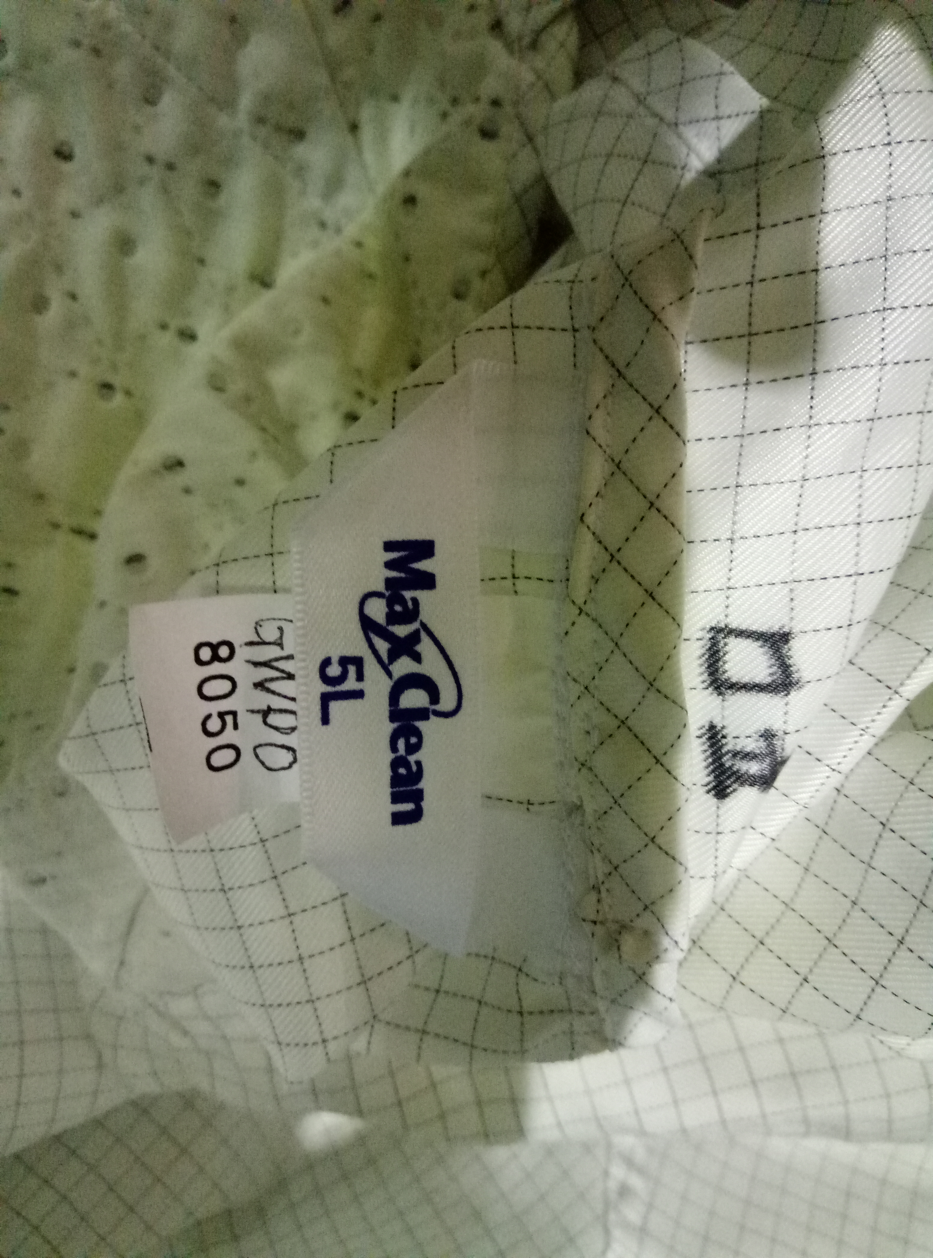
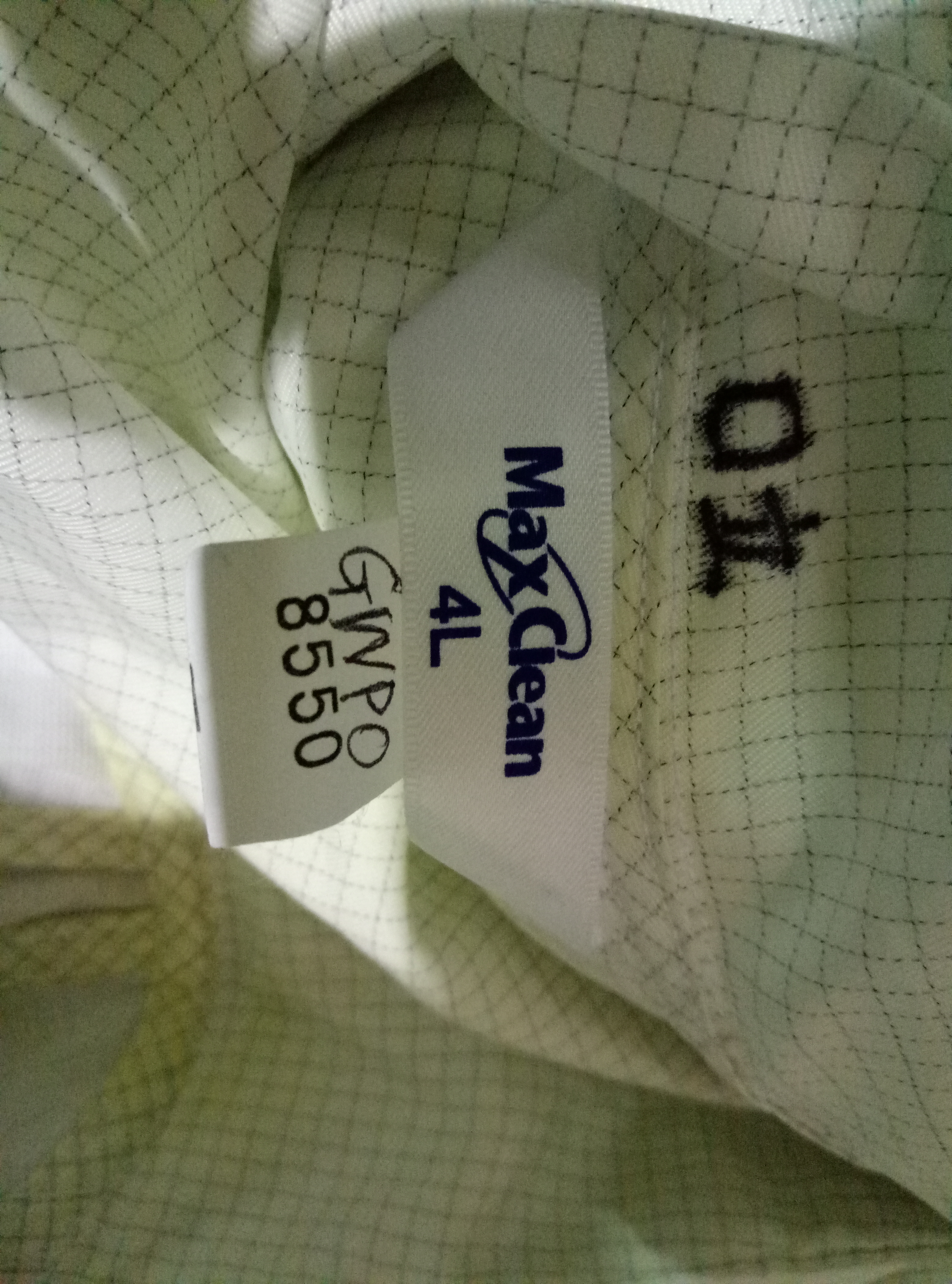
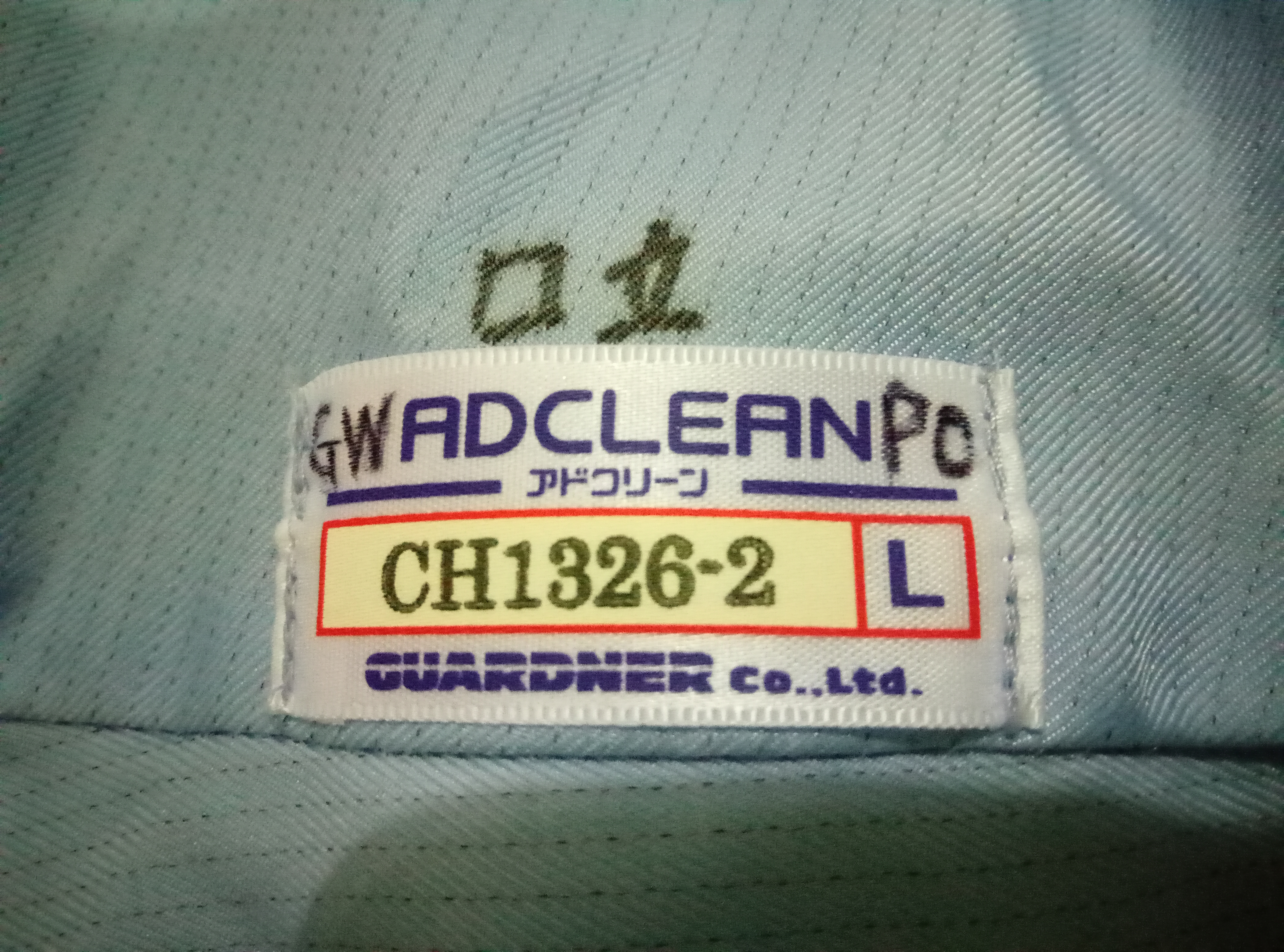
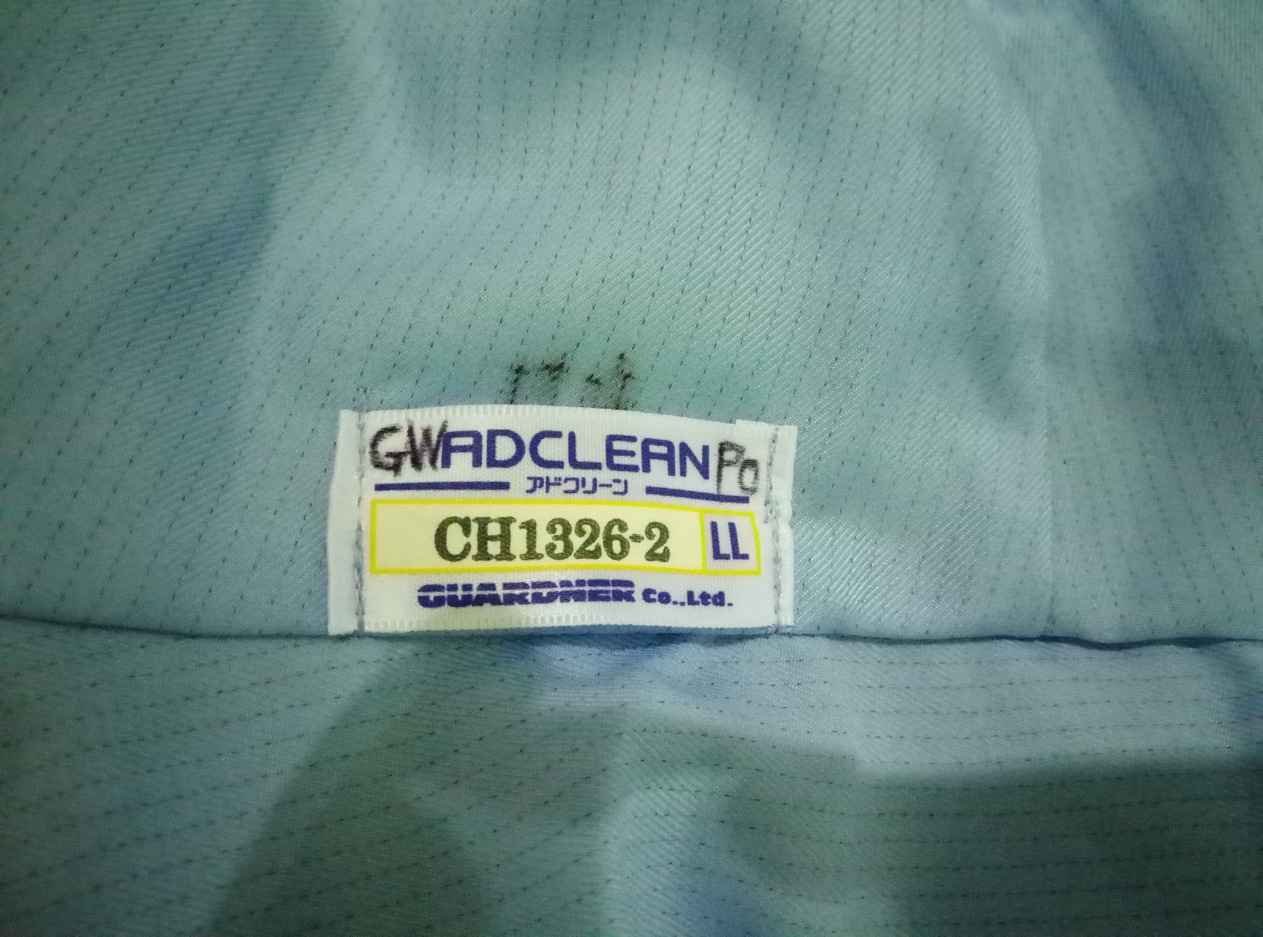
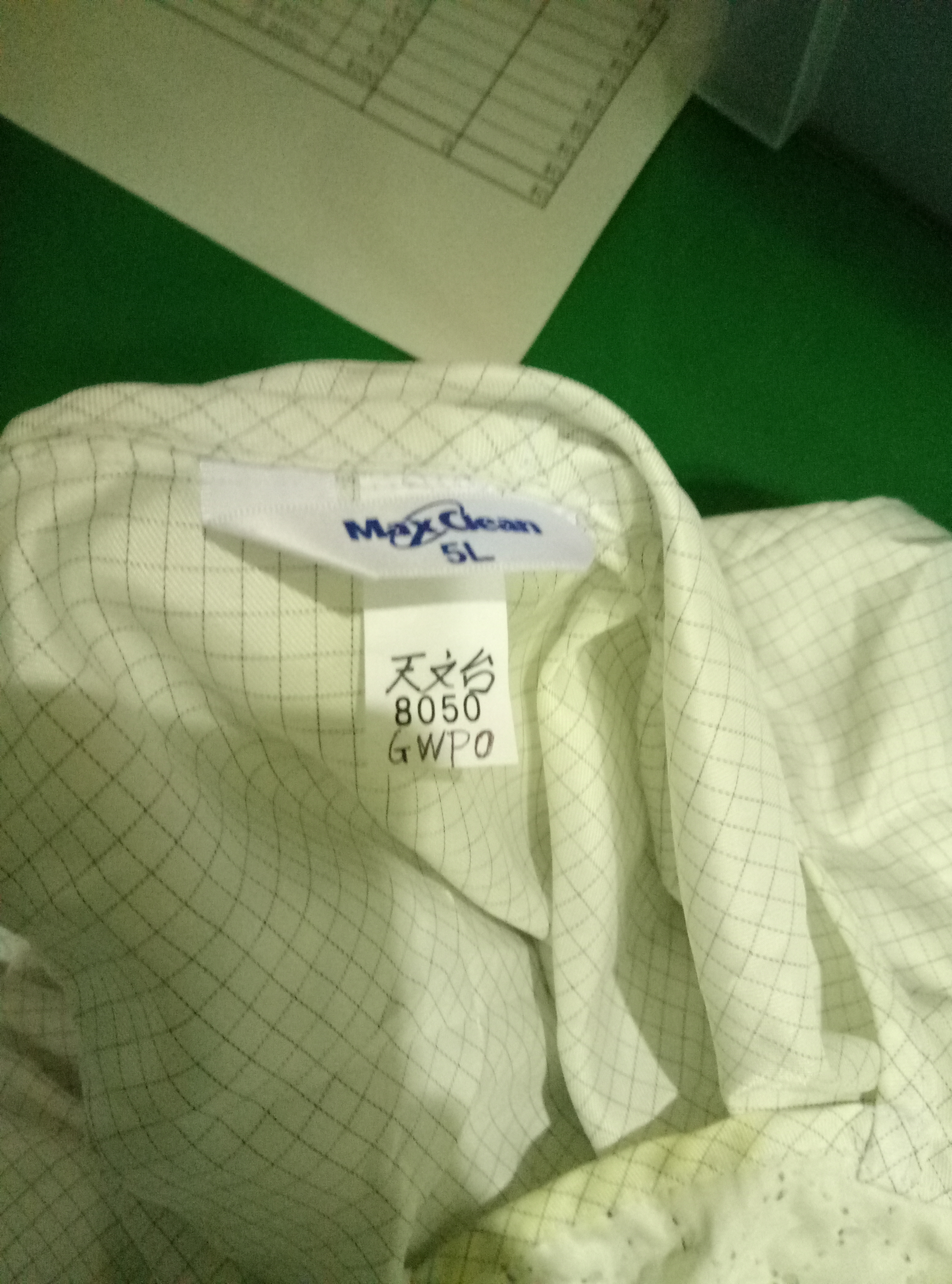
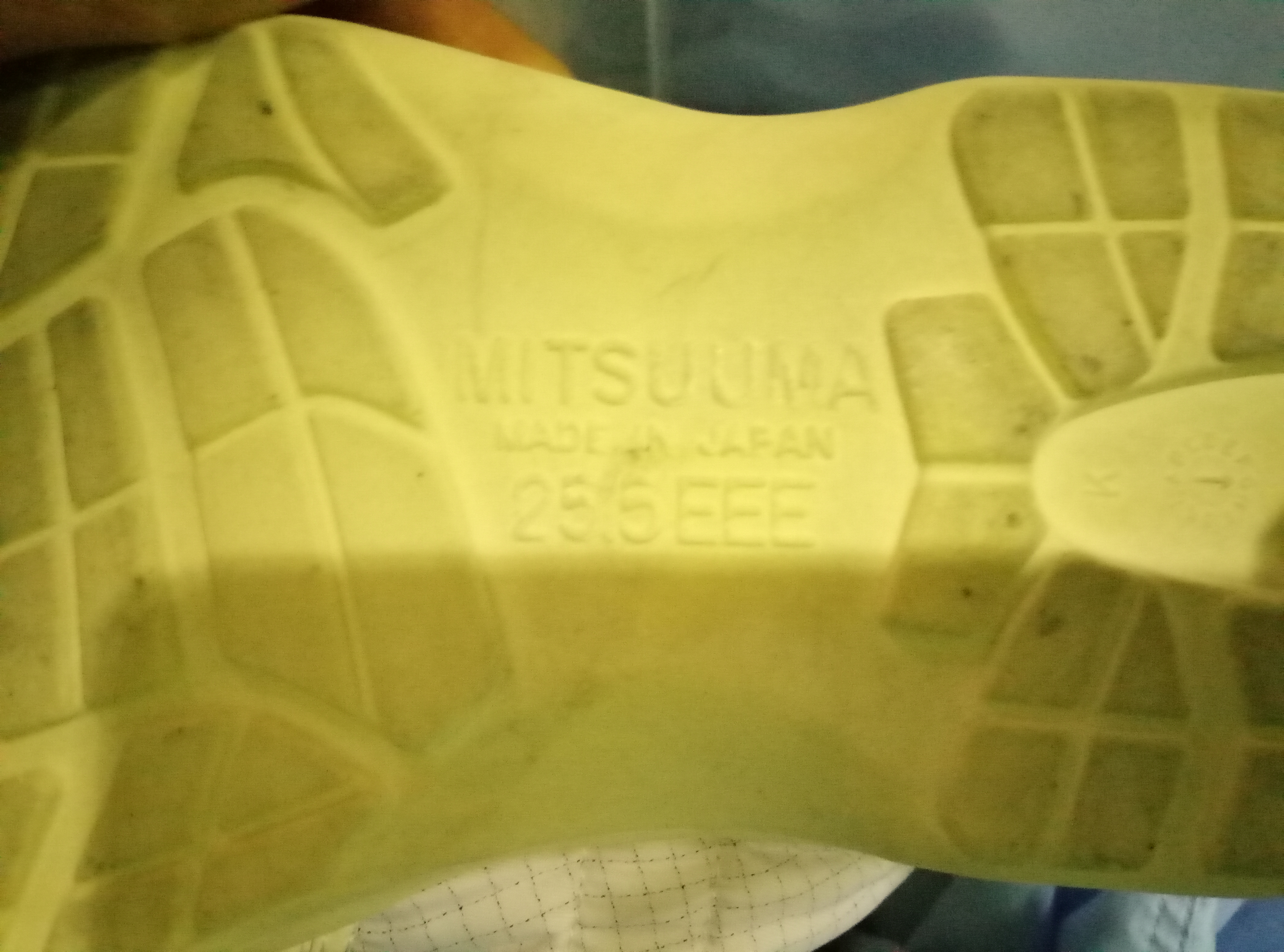
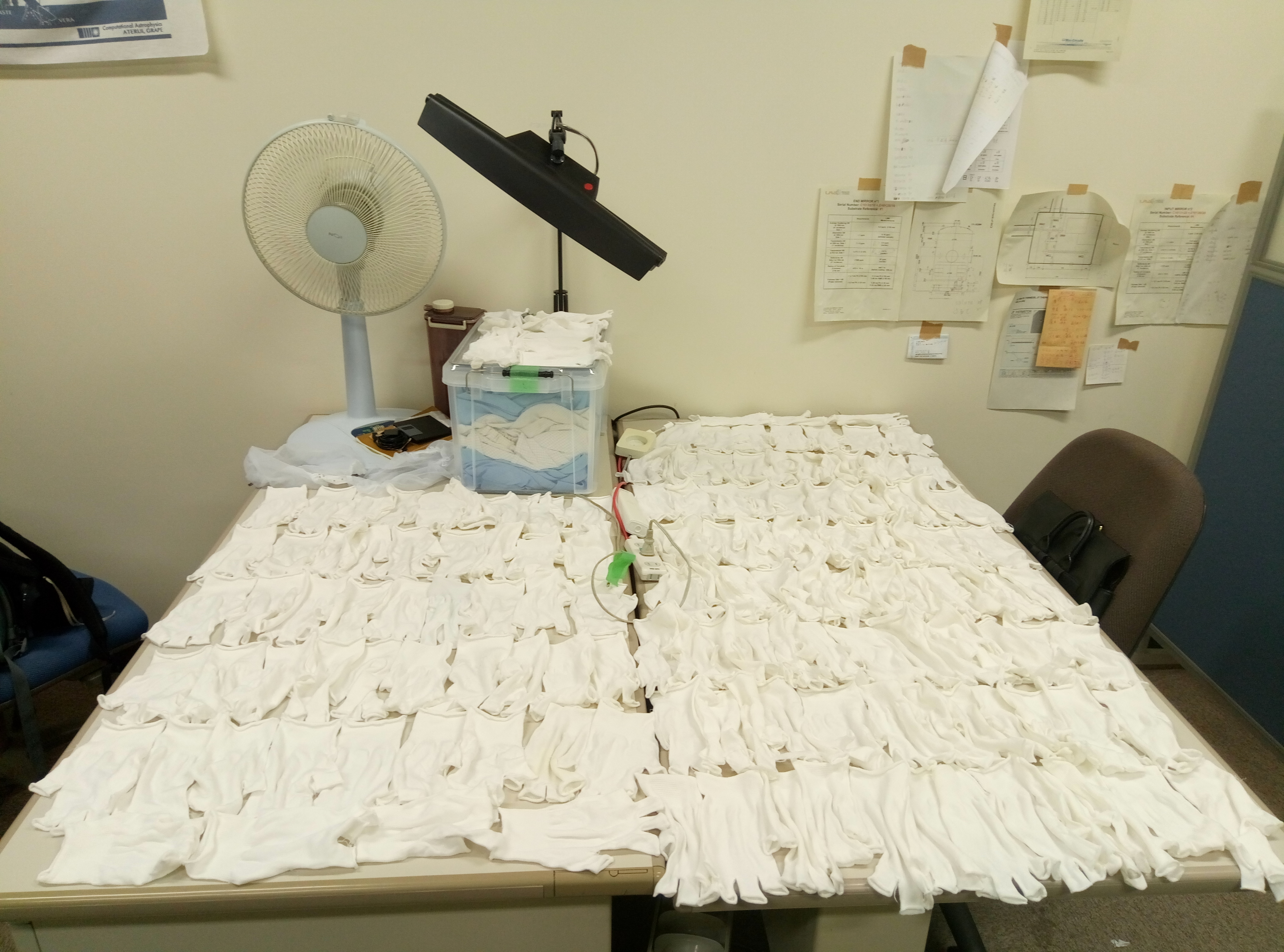
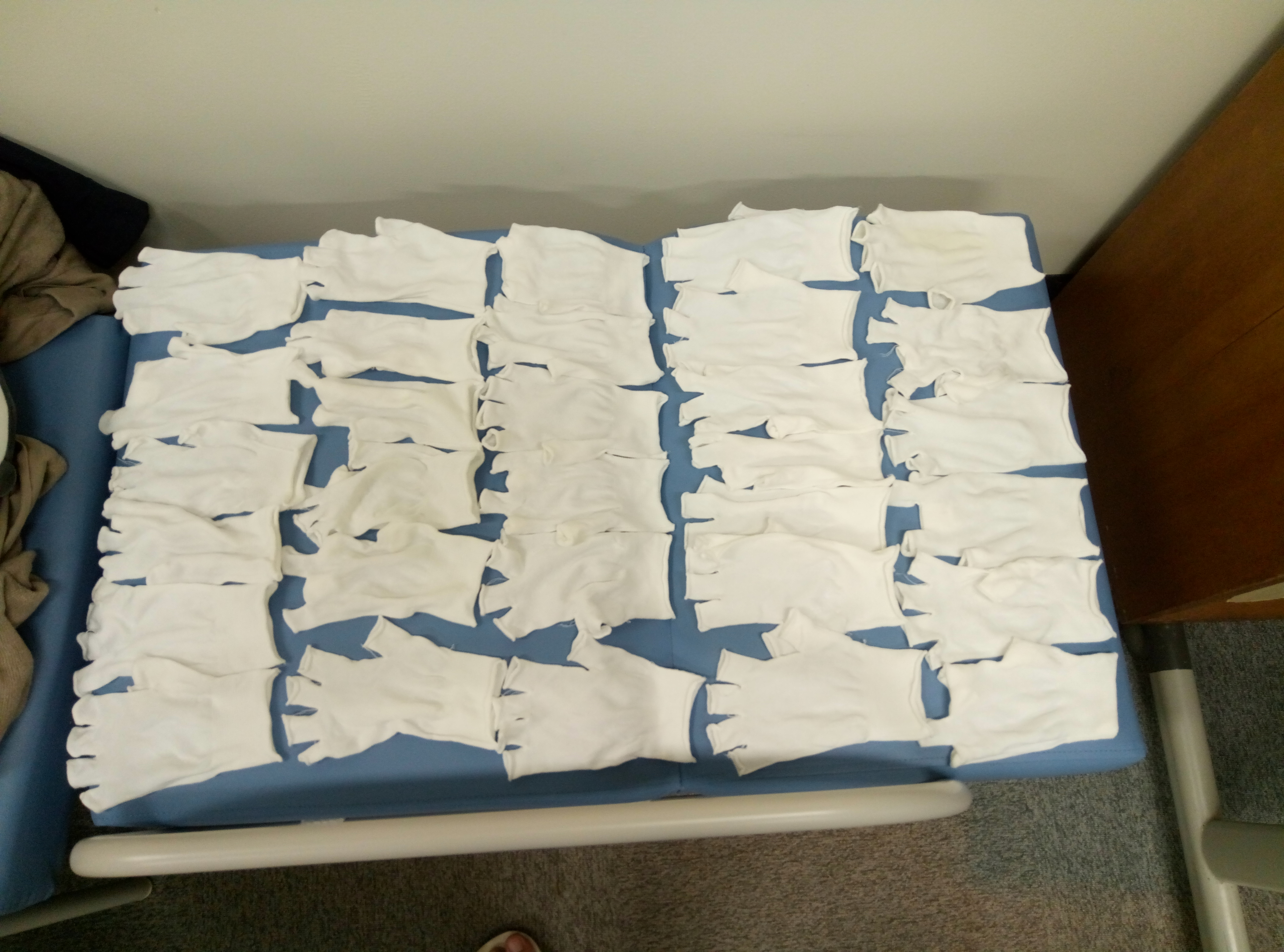
Today I count the clean suit and put them in the box. I wrote 'gwpo' on each suit's lable. I also used the NAOJ washing machine to wash all the gloves we collected. It is quite a lot, I dry them in my office.
| size of suit | L(2),2L(1),3L(1),4L(1),5L(2) |
| quantity of suit | 7 |
| size of shoes | 25.5EEE |
| quantity of shoe | 1 |
Today cube BS arrived, I put it in a desirable position. I found some points to say
Good:
1. It is easy to align cc beam and make it resonate in OPO and produce green.
Bad:
2. After p-pol, I can see very very small peak(around several mV)(sorry I didn't take picture) on the oscilloscope. This may mean we will have problem for locking OPO? Probably this is because of the low power of p-pol.
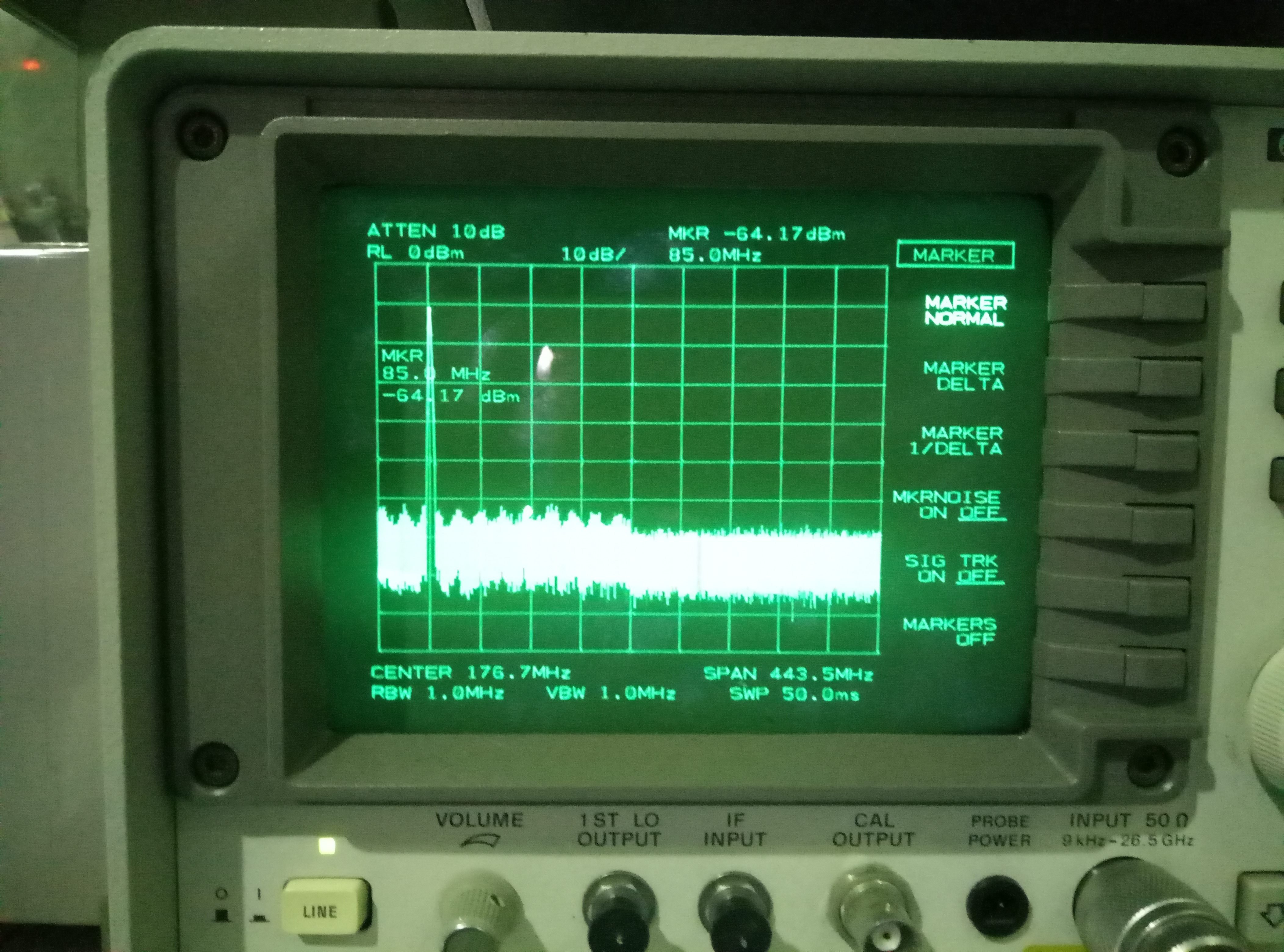
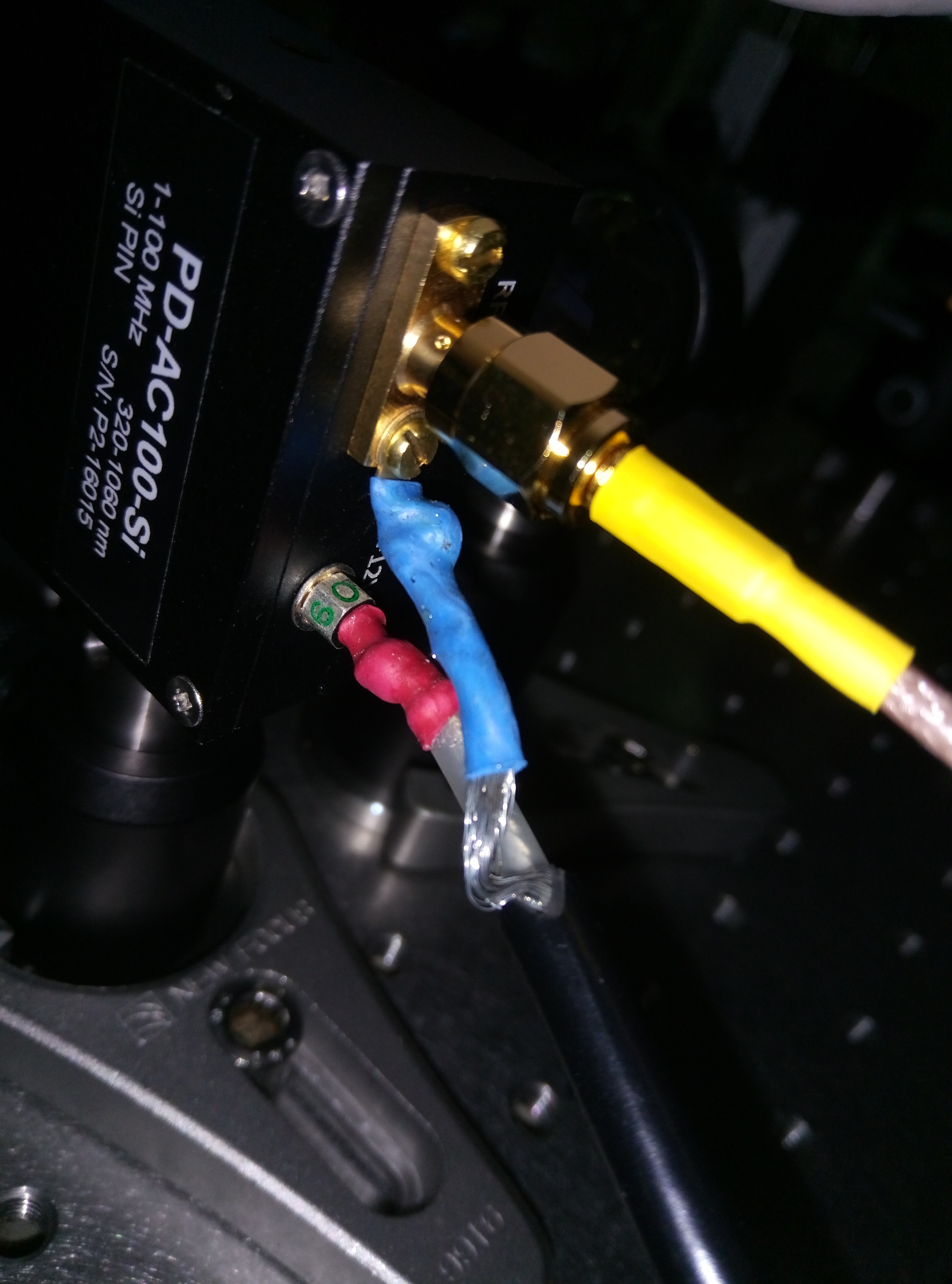
3. The p-pol reflection from OPO goes to the Qubig PD I soildered. However, I cannot find that PD is sensing light. The signal of PD is attached as Fig.1. It seems there is a floor from 0Hz to around 100MHz. I checked light is going into PD properly. I checked even when there is no light going into PD, there is that signal. I also check the soilder I did(in attached figure 2), it looks really the same with another Qubig soilder.
Not good not bad:
4. I found the beam is not going through the hole centrally. This may come from the crystal is not well centered. I also check the SHG's incident beam is not going through SHG's hole centrally. So maybe this is fine.
The frequency shift between cc and p-pol is used for the coherent control in the future. At the same time, we need to control this frequency at a certain point with a proper value. This is pretty similar with the double control of infrared and green resonanting inside the filter cavity. In FC case, we use AOM. Here we use PLL to control this fixed frequency shift.
Today I set up the PLL and it works well.(see attached picture) Note here the singal is 1/10 of the signal. However, since we use PBS while we are aligning OPO, we need to take it out to make p-pol and cc both go to OPO. The reason is we will use cube BS in the future. We use cube PBS to simulate the optical path change by the substrate. Taking out cube PBS change the phase of beam quite a lot. It makes beam not resonate inside OPO. So I stopped today's experiment. We will wait the arriving of cube BS.
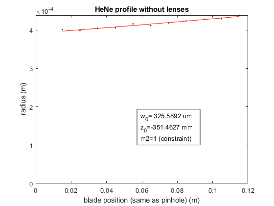
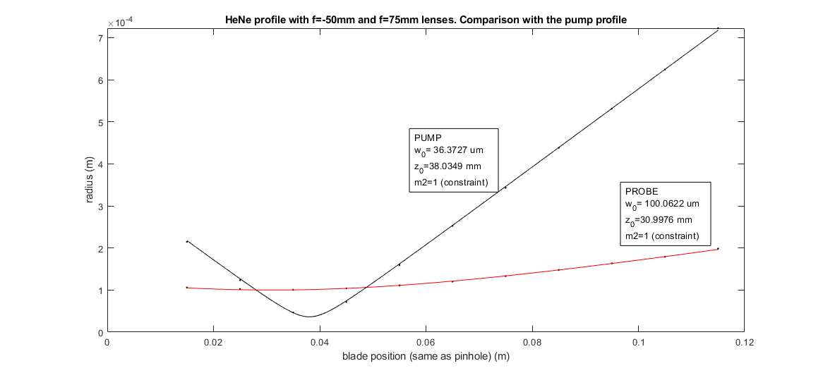
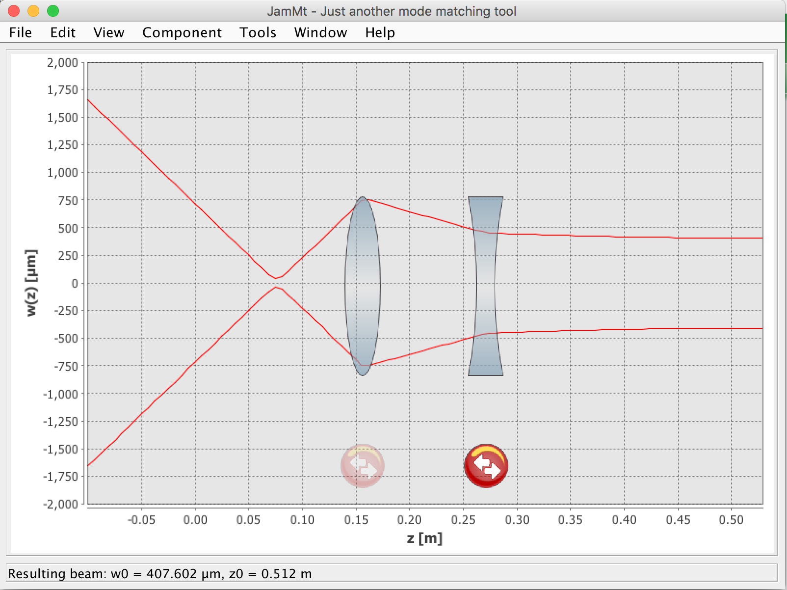
In order to reduce the size of the HeNe probe I used Jammt to design the optical path.
First I measured the profile without lenses. First plot. The axis is in the translation stage reference. The waist of the HeNe is right at the output of the laser tube.
After some attempts, designs on Jammt and profile measurements, I found a good set of lenses to have the waist about 3 times larger than the pump.
The lenses are a f = -50mm lens and a f = 75mm lens at about 47mm from each other. The second plot shows the final probe profile. The probe size is now 2.8 times larger than the pump.
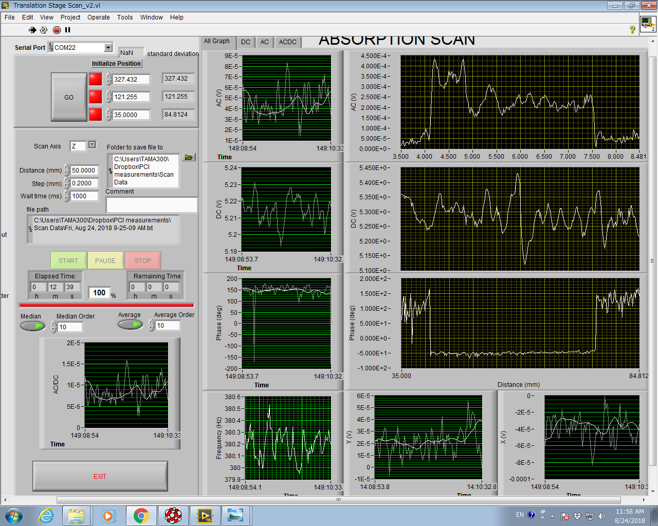
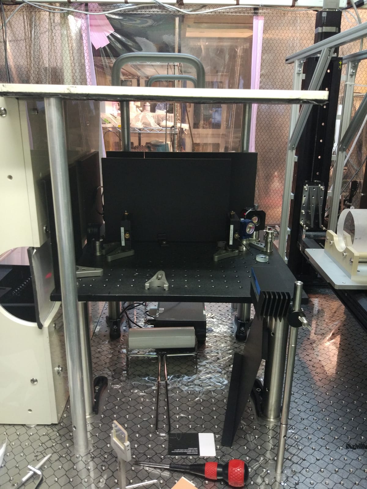
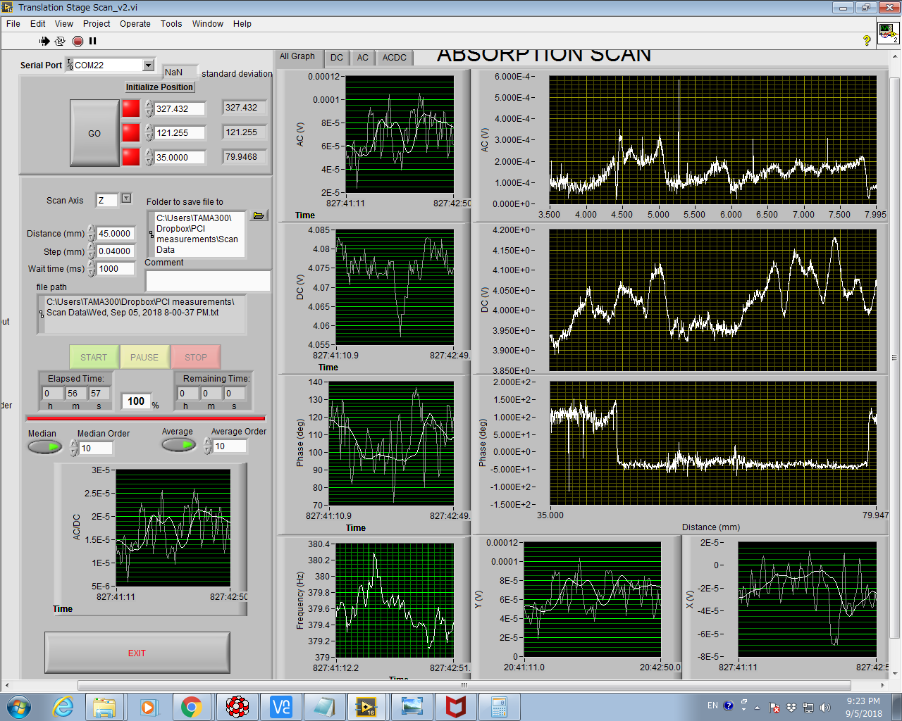
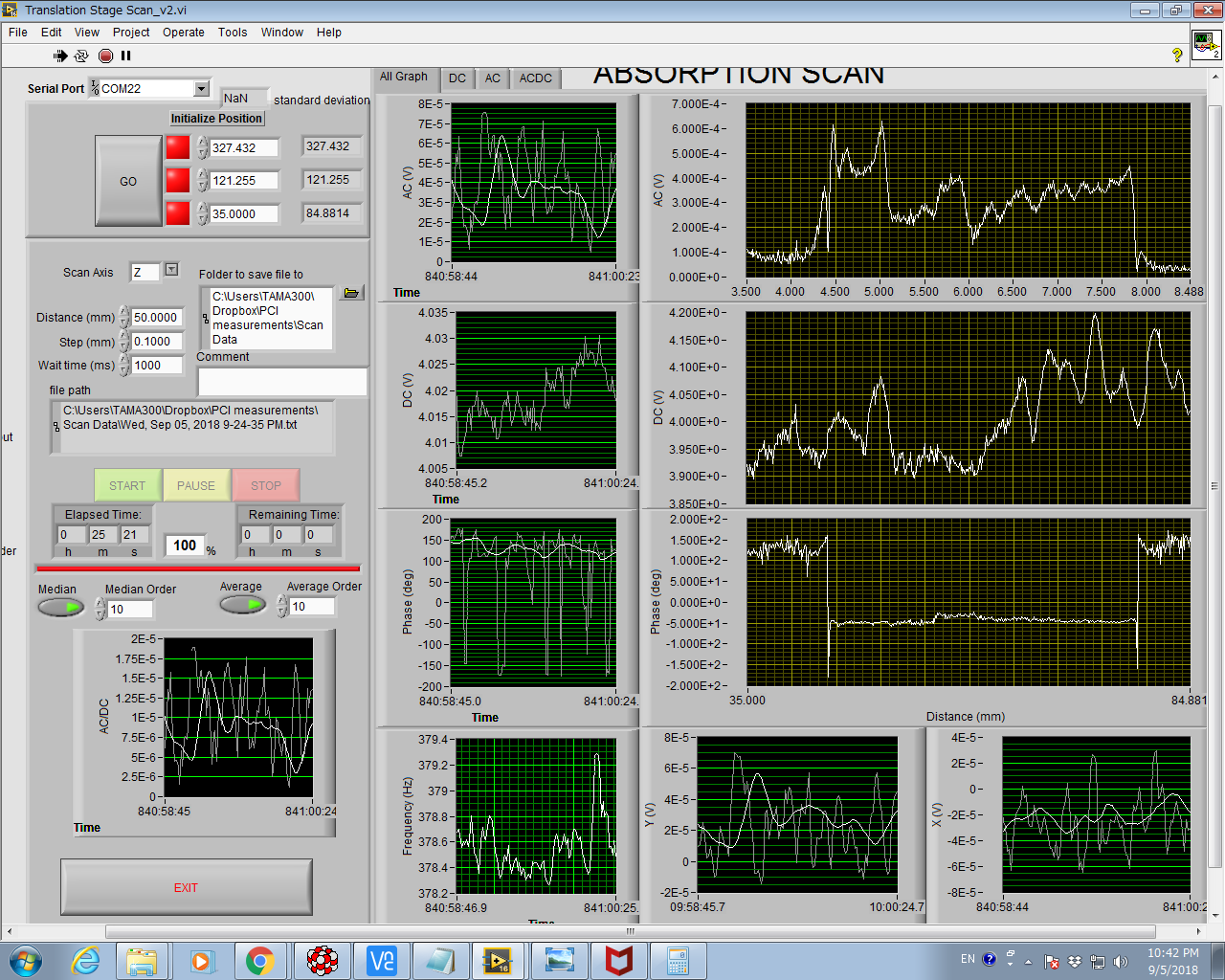
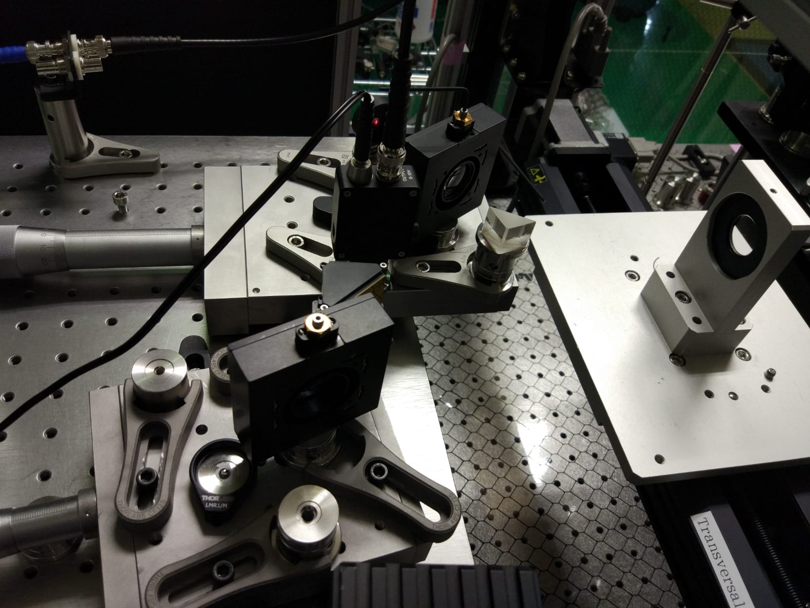
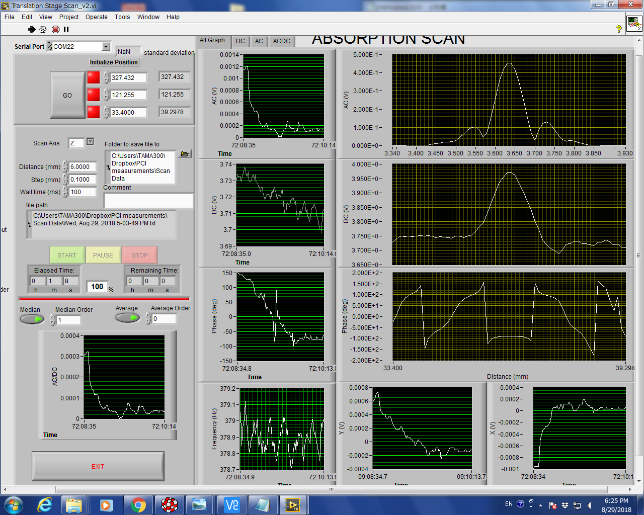
I aligned the pump and the imaging unit to maximize the signal on the surface reference sample (usual procedure). Then I scanned the bulk calibration sample.
When moving the Imaging Unit with the micometric screw to finely maximize the AC signal, I noticed that there was not a clear maximum in the range. So I unclamped and moved the whole IU much closer to the sample. At about the same position as it was in the very original setup. Now all the conditions are the same as the original setup, or at least as the specs say.
Now I'm wondering if/why it is not possible to have the same size of the image on the detector when we move the telescope further. This is to be cleared.
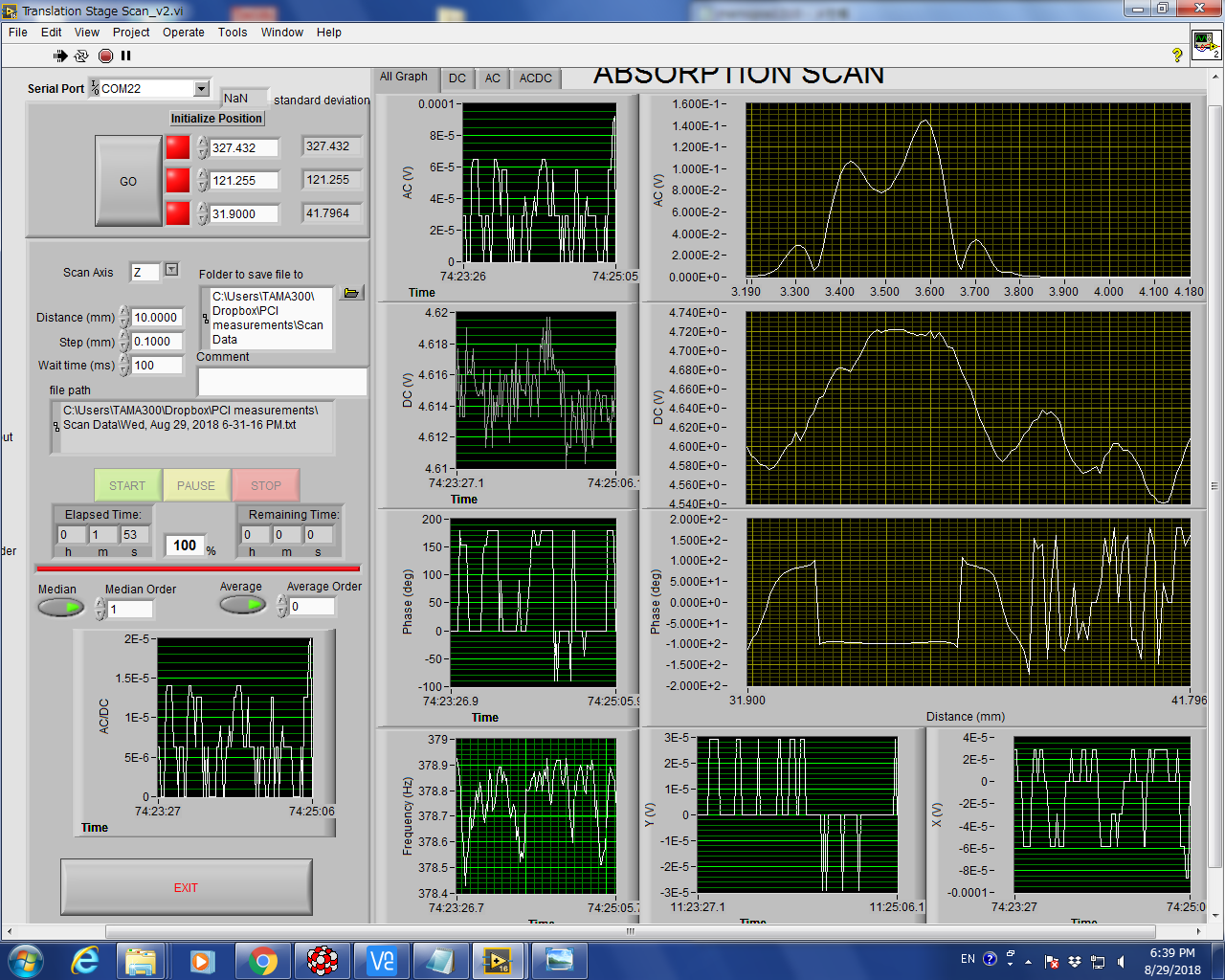
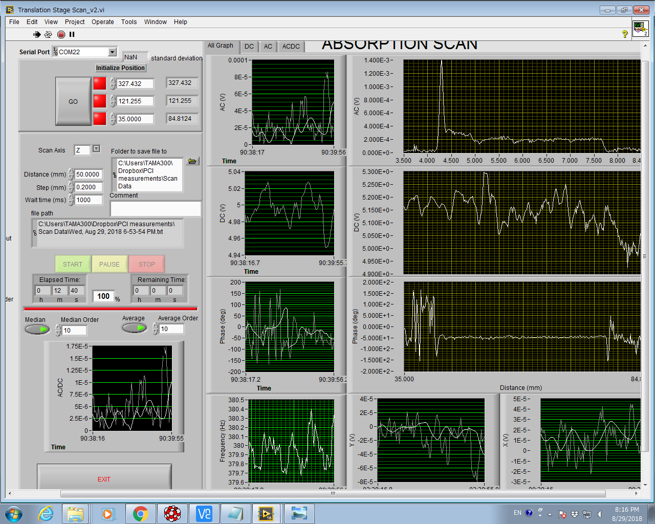
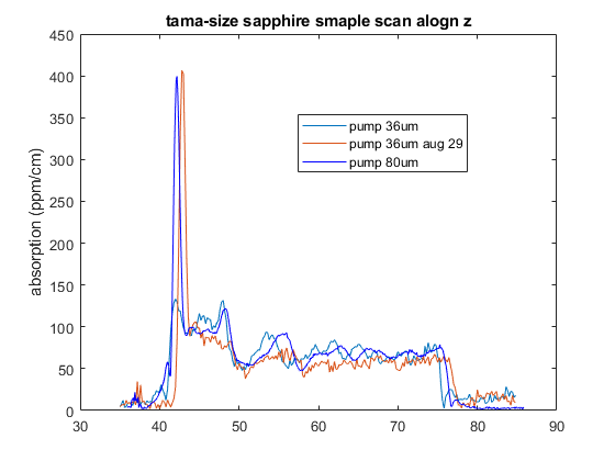
Then I measured the tama-size sapphire sample again. First with 5W of pump power and then with 10W (max). Noise from chopper (constant phase) is again a bit high, but let's consider this later.
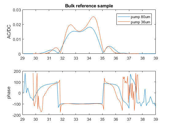
In the last plot I compare the last sapphire measurement with the one of last week, when the probe was larger. Remider: reducing the pump size without reducing the probe size didn't change the signal.
Now the absorption value is smaller. It's not straightforward to tell a precise ratio, but let's say it is between 1 and 2. It is certainly not a factor of 3, as we would be very happy to have.
I have the feeling that the calibration factor between materials (3.34 according to STPS between sapphire and Schott glass) depends on all the parameters I changed.
What I really don't understand is how the imaging affects the calibration. I thought that the image size depends on the focal lengths of the telescope lenses only, not on the distance of the telescope, but maybe I'm wrong.
The question is: let's call d1 the distance from the sample to the first lens of the telescope and d2 the distance between the two lenses. Is there a d2 for each d1 so that the image on the PD is exactly the same (in sharpness and size)?
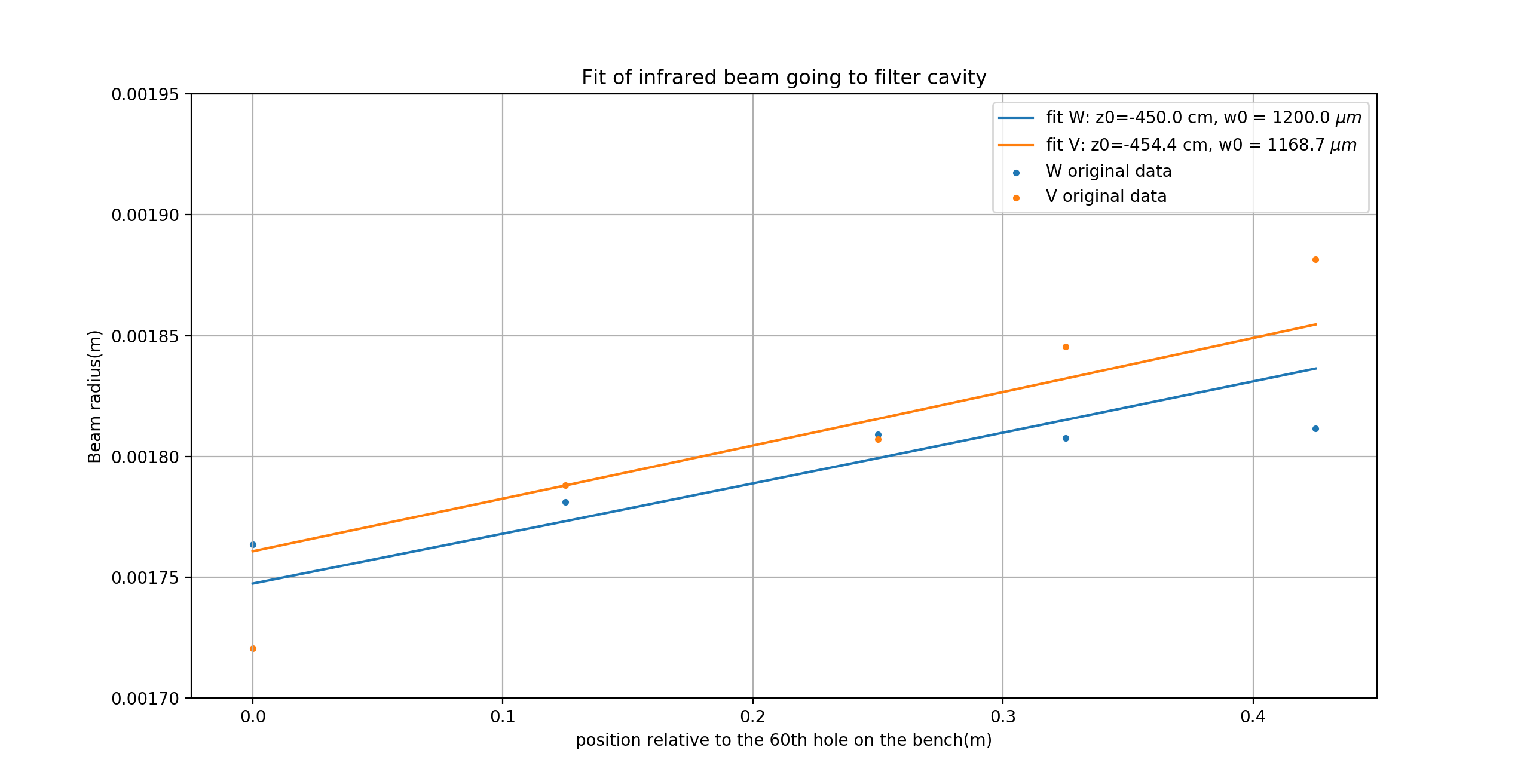
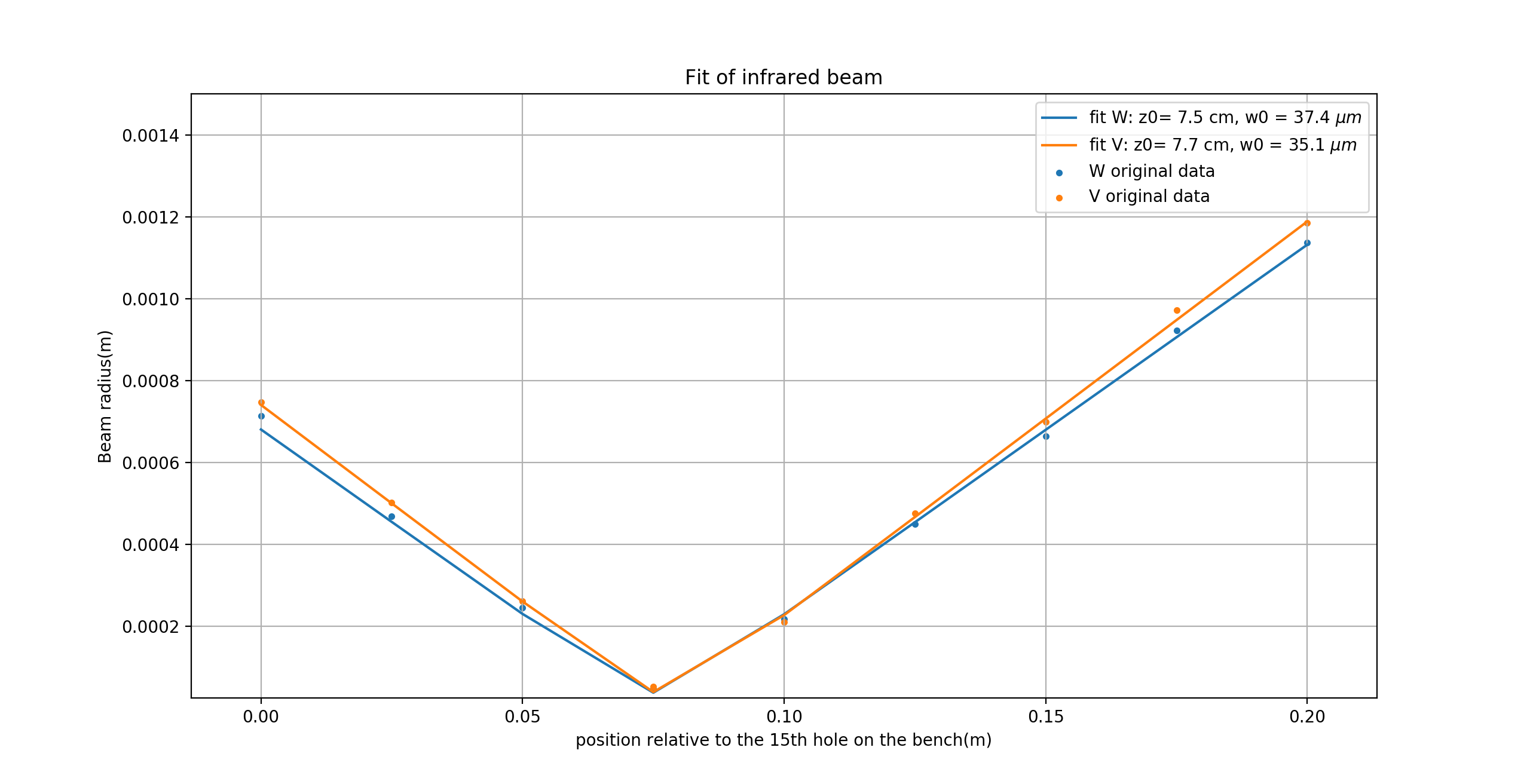
Yesterday I did beam characterization of infrared beam along west and south edge of bench. The first attached figure is along the south edge, which is also the beam directly goes to PR chamber. Actually we did a similar characterization before, see elog634. This time the result is similar with before.
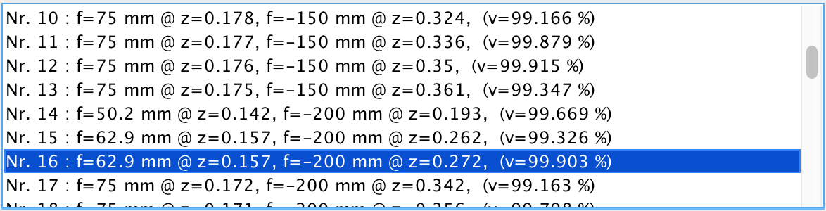
The second attached figure is along the west edge, which is after the first lens on the rail. We will put a combination of lenses to make the beam meet the requirement of IR mode cleaner. According to the measurement result, we have the initial beam information. We also know the target beam information, which comes from calculation of IR MC configuration. Then I use these information did the simulation in JamMt by using mode matching assistant. I choose one I prefer showing as attached figure 3 and 4. I checked they are seating at place between lens and first steering mirror. This means it should be a reasonable solution. Also this solution doesn't use small focal length lens.
The detailed calculation is also attached in PDF file.

Today after I installed the first lens, I check the beam parameter. It is quite far from the simulation. Then I found the reason maybe I didn't use a correct distance before. (Also here I found 200mm lens disappears)
Then I measured the beam again and used the lens we have to design the telescope. However I cannot get any result.
So I decide to remove the first along the west edge. Then I peformed the measurement. Before do that I aligned the beams to make them flat and go through the center of the lens and mirror as well as possible. Then I measured the beam agian. The result is w0 = 850um, z0 = 3.05m(relative to the 0th hole of west edge of the bench).
Then I use the result and mode matching tool in Jammt(by using the lens we have, I just update the lens situation today). The target beam parameter is calculated last time. It is w0 = 390um, z0 = 0.8875(relative to the 0th hole of the west edge of the bench).
The simulation result is f = 250mm @ z = 0.484m, f = 75mm @ z = 0.795m. I also check this result with the optical layout we have. It doesn't overlap with the mirror we have in the optical layout.
Yesterday, I got more information from Matteo. The reflectivity of crystal should be 99.975%. And for in-coupling mirror, it is 92%. By using formula, T=T1*T2/(1-r1*r2)^2, the updated transmission should be 1.192% without considering losses. Now what we found, transmission of 0.25%, seems resonable.
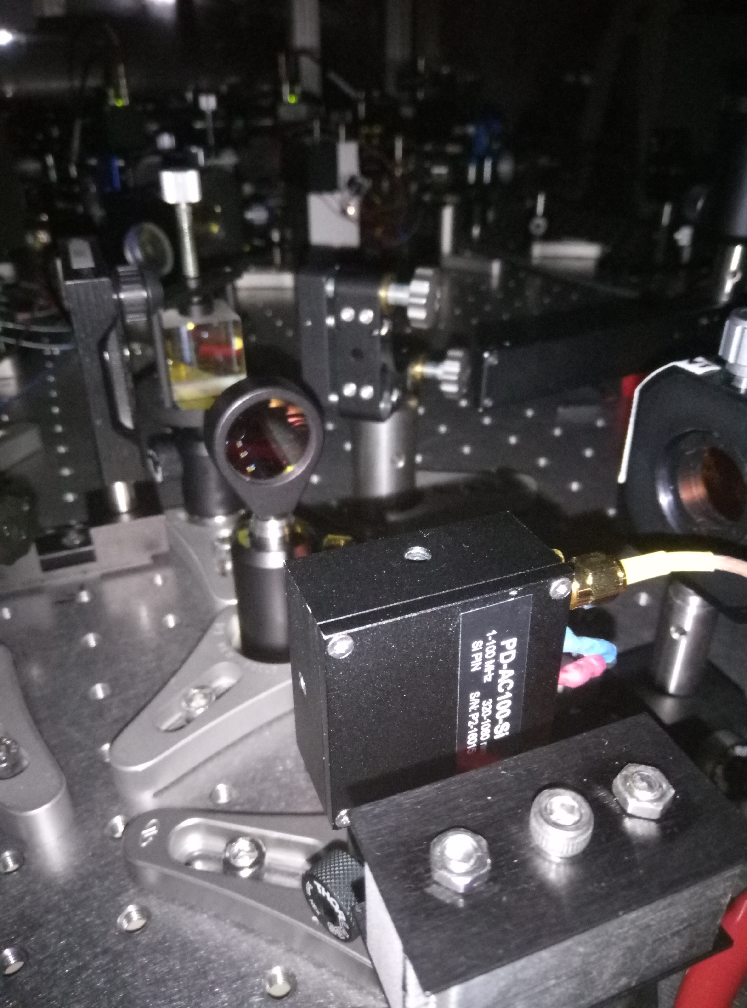
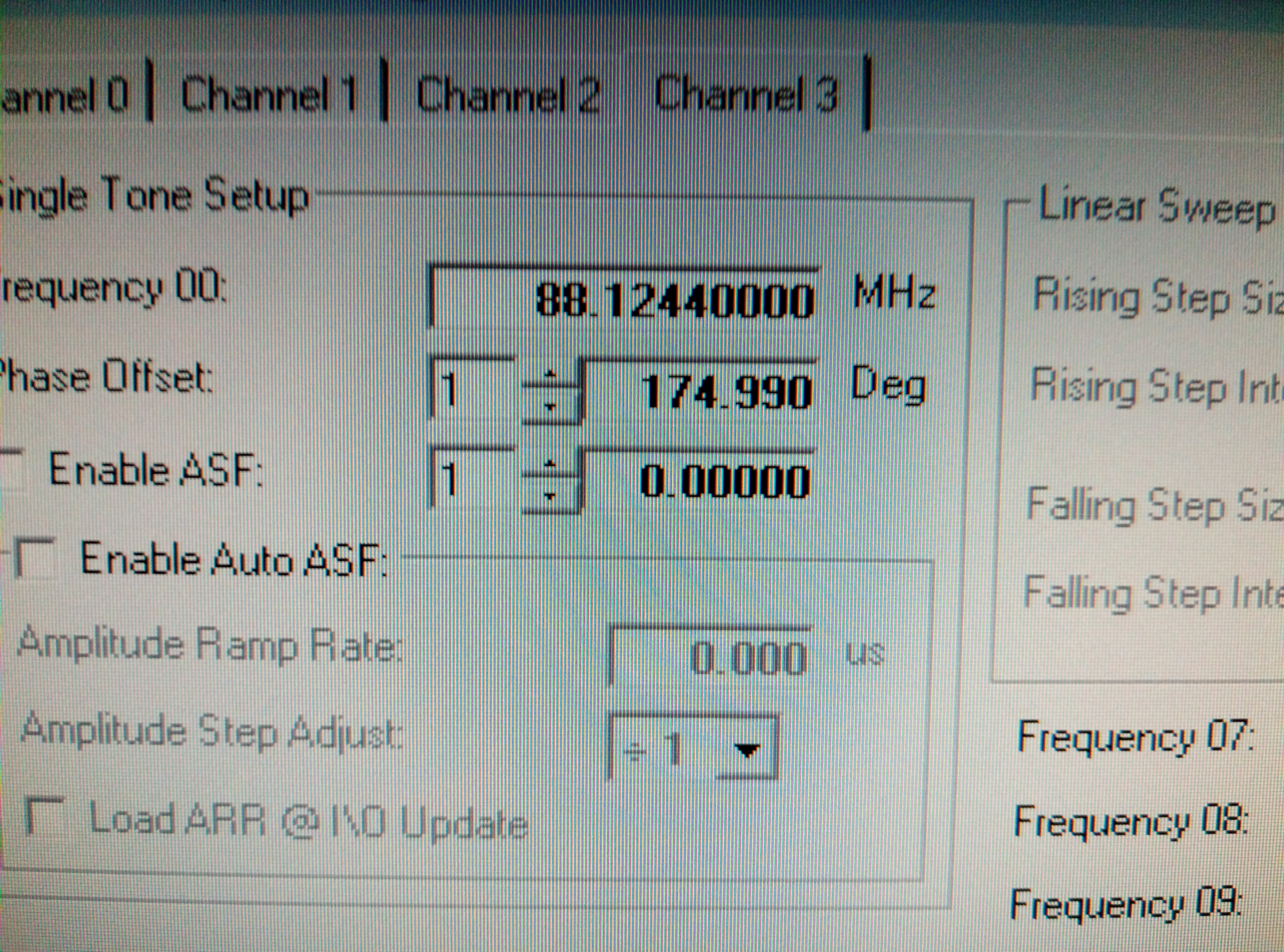
Today I also soildered the Qubig photodiode.(see attached picture 1) According to the specfication, the resonant frequency of EOM is 88.1244MHz. I set up corresponding frequency in the DDS board.(see attached picture 2) Then I did the test of Qubig PD. However I didn't put the PD in the final position. The reason is we don't have the cube BS. If I use plate BS, I will shift beam a little bit and may destory the alignment of OPO. Now Matteo is trying to order it. Hope it will arrive soon.
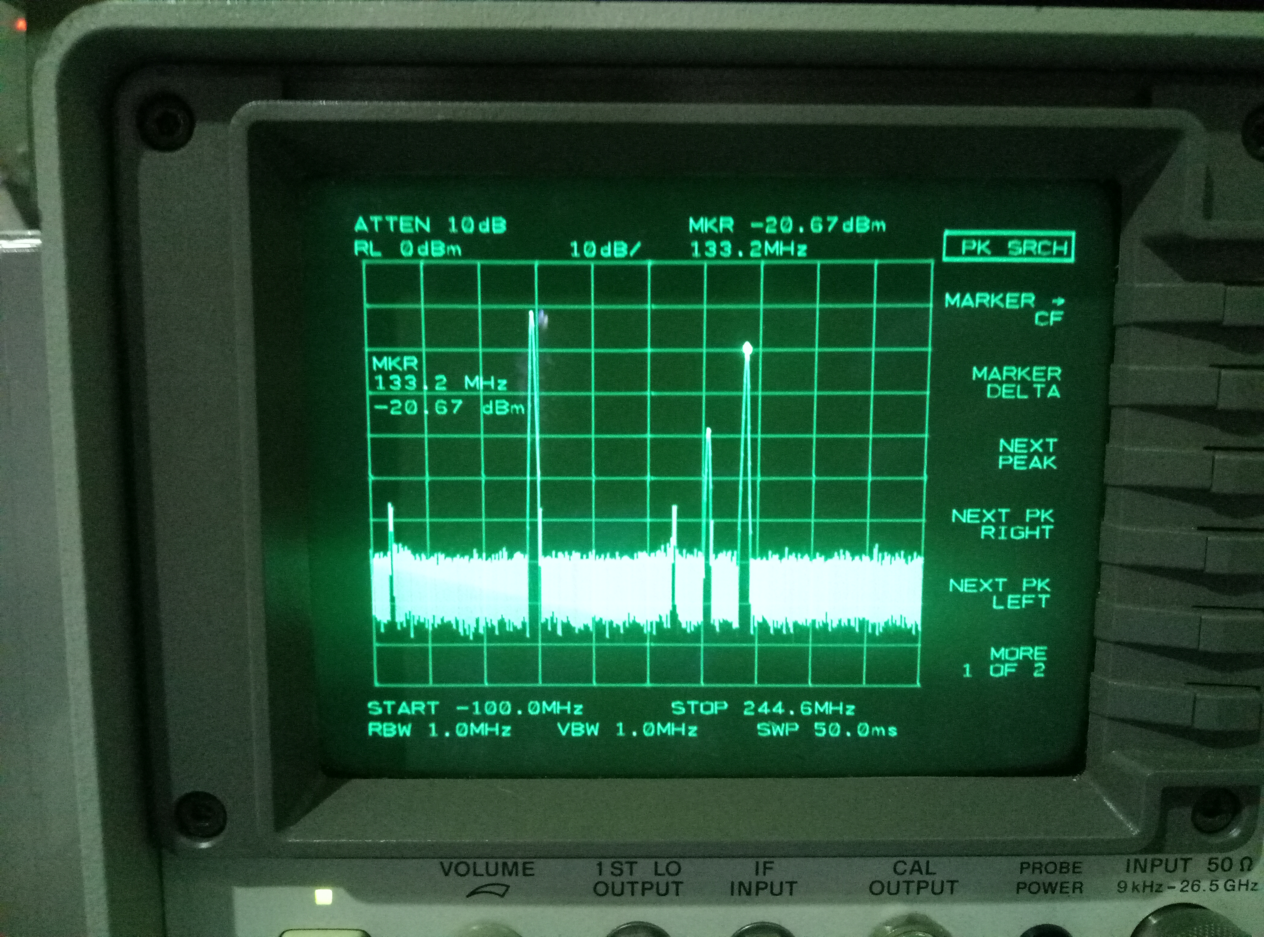
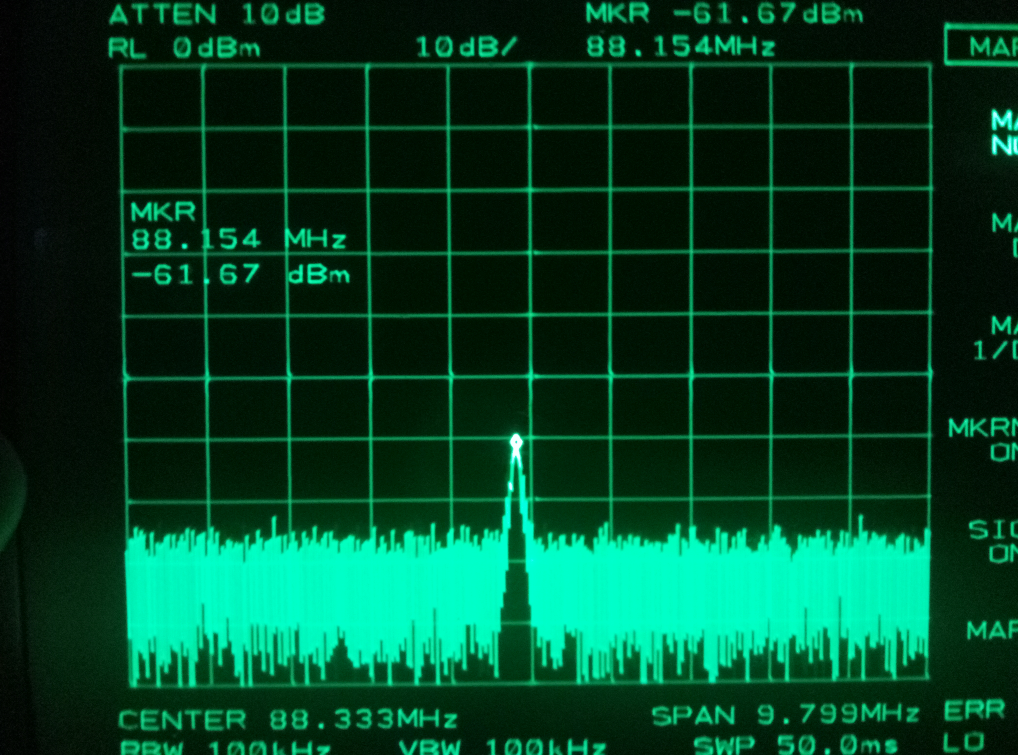
So I put it at the reflection of PBS, since we have some residual s pol(around 140uW which is luckly a good value for PD) in the p pol beam. I measure this modulation in this perspect. As expected, the level should be low. But we can use this small effect to test EOM and PD. And I found both of them are working well. (see attached picture 3)
COMMENT: I talked with Matteo, he pointed out what I saw should be the comunication between two channels. I checked today that that peak should be the communication. We will do the test after cube BS arrive.
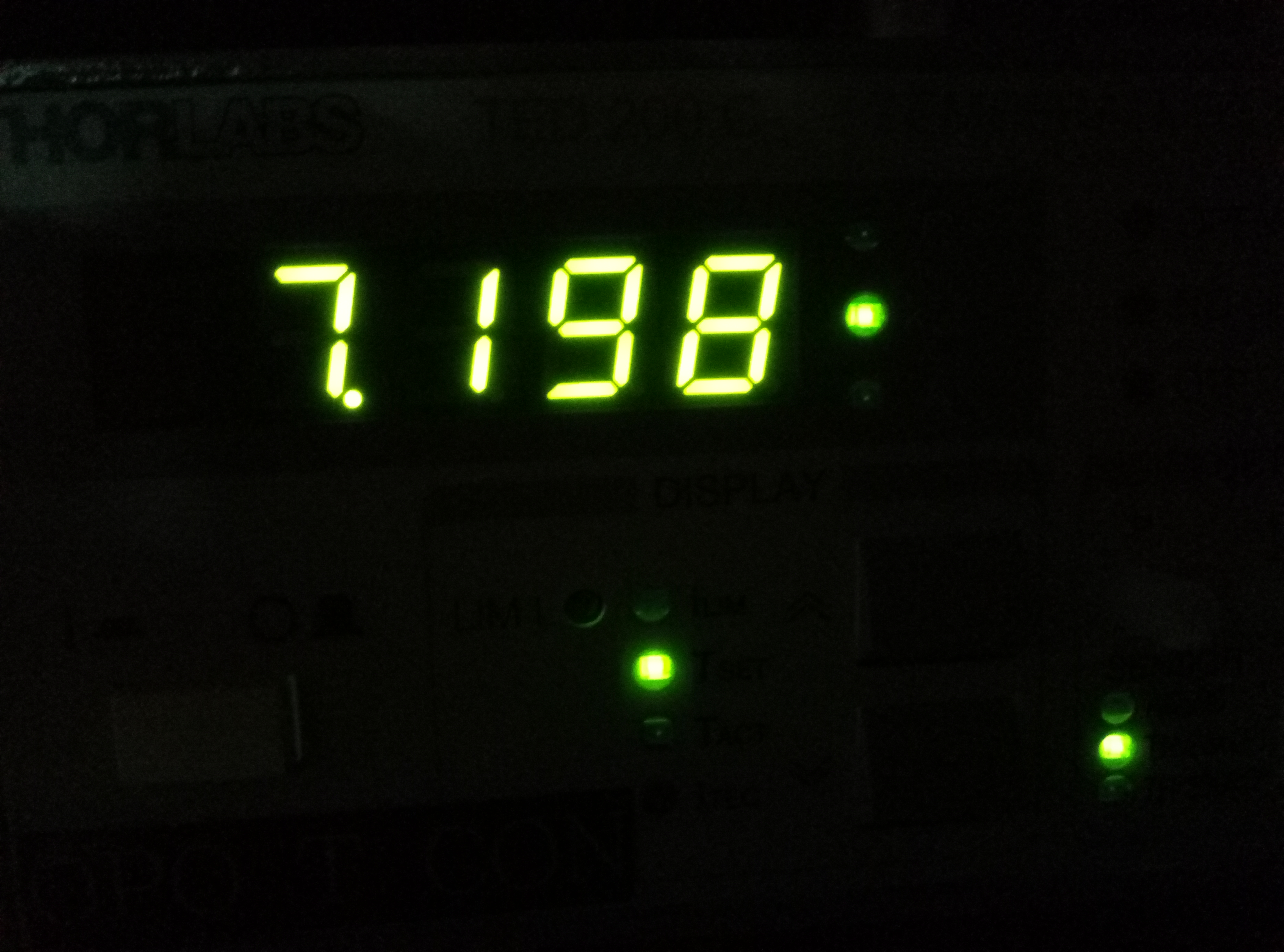
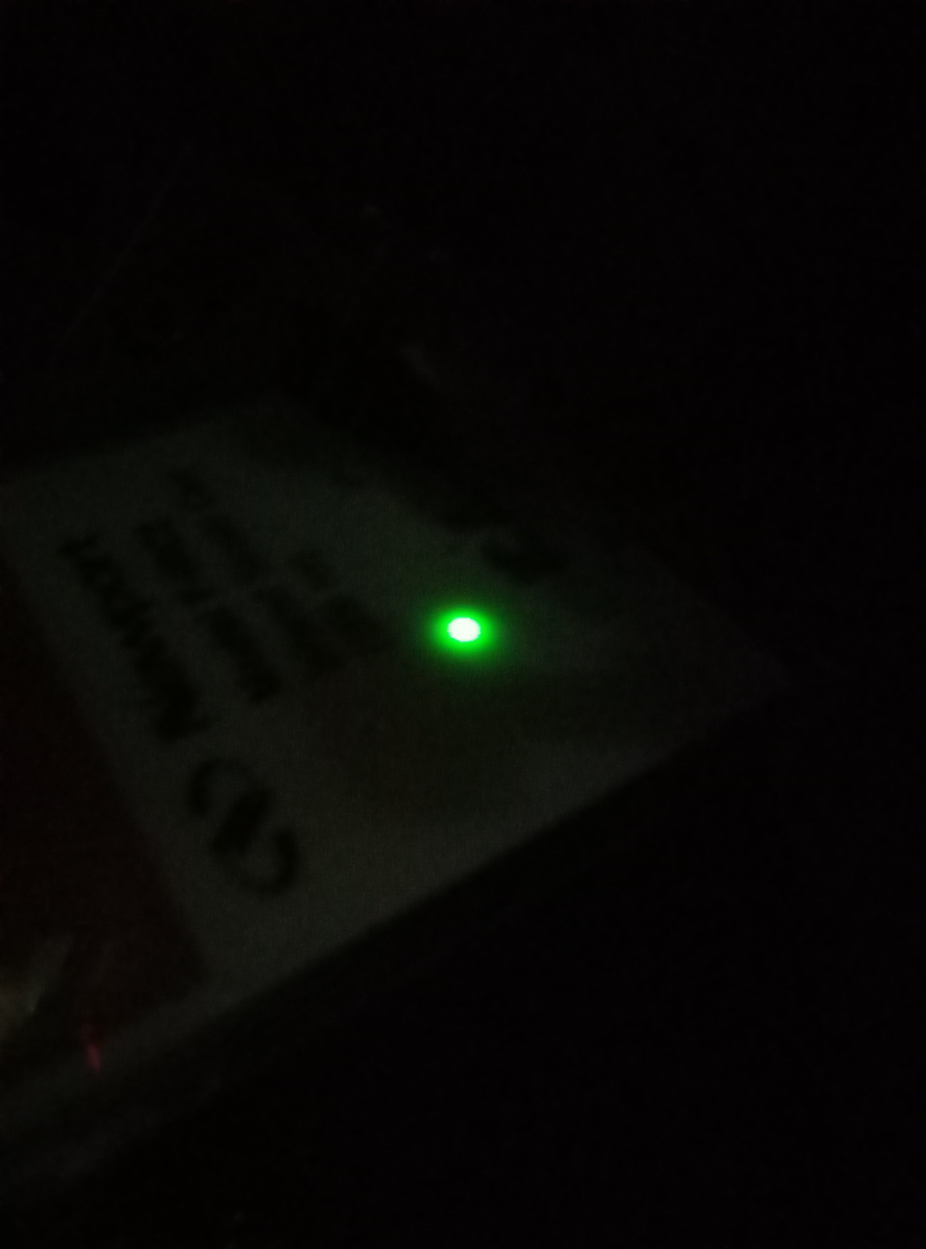
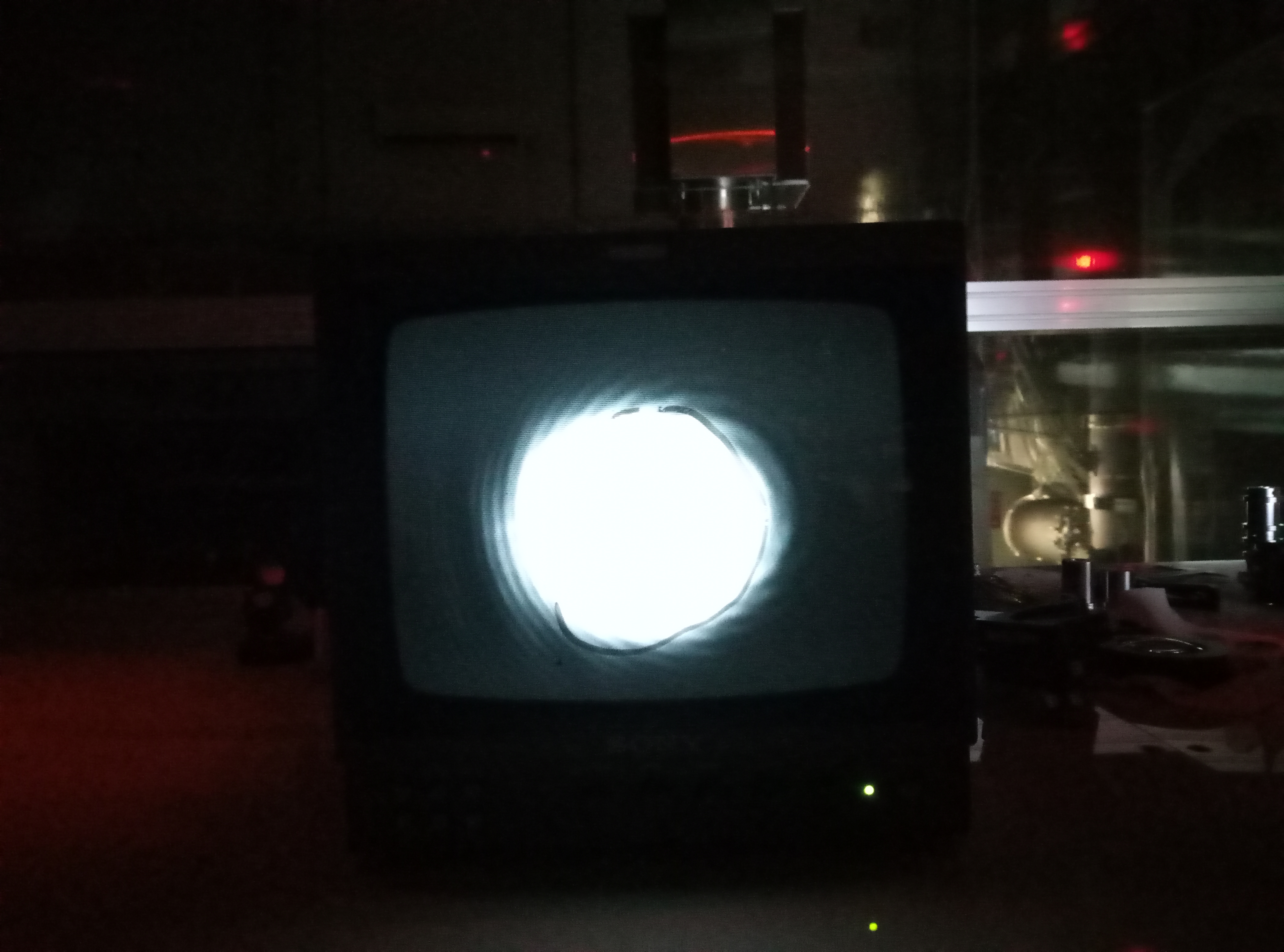
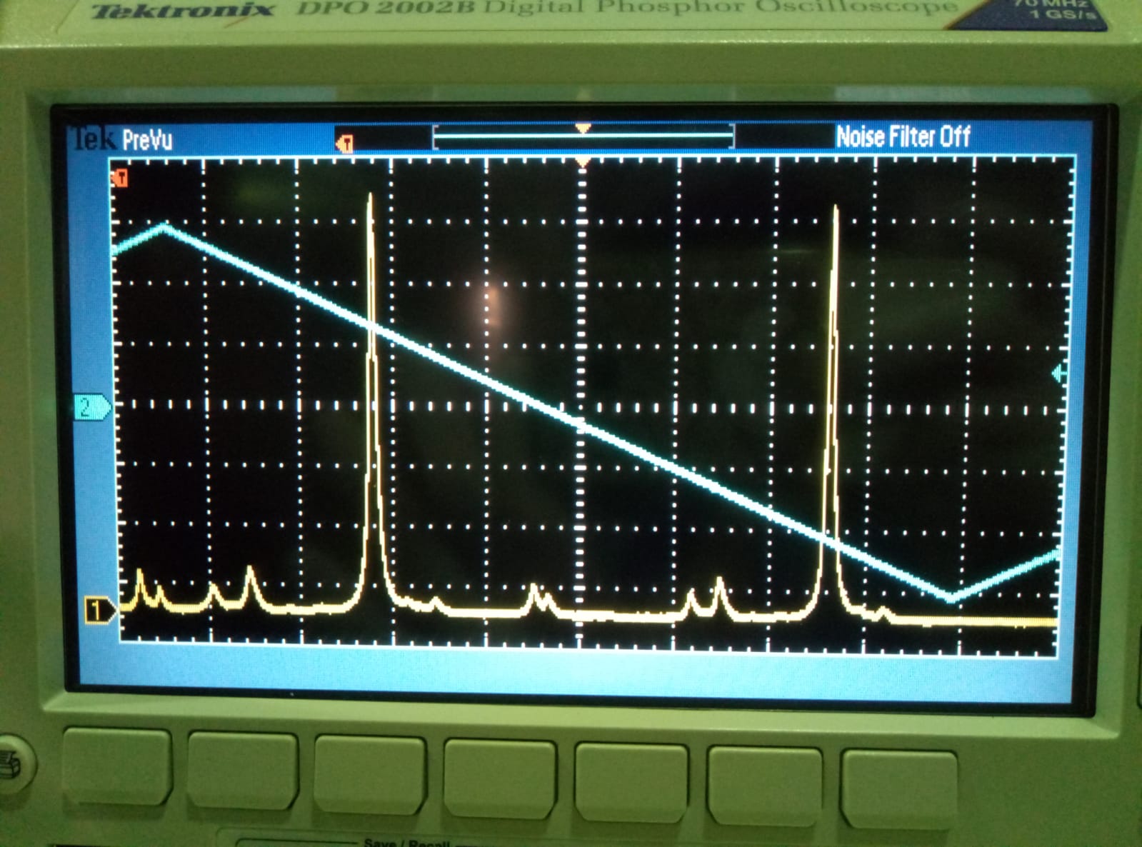
Last entry about OPO alignment is done with the transmission of OPO seperated by normal 50:50 BS. Today I replaced it with a BSY11(dichroic mirror reflects infrared). The first time we align OPO with a temperature of 6.740kOm, but now I found I cannot find green with this tempereture. So I did a scan of temperature, I found green transmission in another temperature. The temperature now is 7.198kOm. (See attached picture 1)This is a roughly fine value, we will find the best value after the lock of OPO. See attached picture 2 of the green I found. And picture 3 of it on the screen. I check the value of infrared transmission again today, which is around 0.4mW. It is similar with last week's condition.
Participants: Yuhang, Eleonora
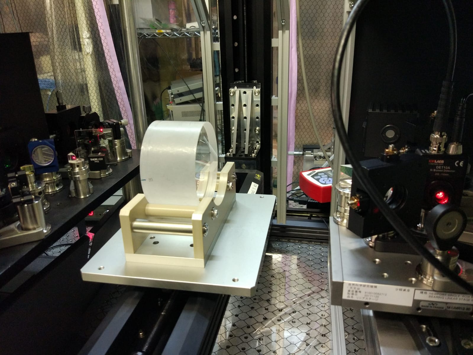
After achieving the OPO internal alignement (entry #963) we removed the set up we used for this activity (periscope etc..) and we placed the OPO in the final configuration on the bench. (See optical scheme on the wiki updated by Yuhang )
The first rough aligment was done with low power p-pole beam, placing the OPO in order to have its reflection superposed to the incoming beam and then using the last two steering mirrors for the fine alignment.
At the begining we had some trouble with the piezo: since we were only able to get some slowly drifting mode of the camera in trasmission, we suspected that the piezo was not working.
First we check the piezo driver (which was fine), then we check the small box containing electrical connection between BNC from piezo driver and the piezo wires. As soon as we opened the box the piezo start working again. We observed that it was very sensitive to touch. To be checked further.
In the end we could achieve a good aligment, using CC beam (s-pol). See Pic.1. Anyway the trasmission seems much lower than what we expect.
We had only 0.5 mW trasmitted power over 218 mW of the input beam. That is less than 0.25%.
Assuming R1 = 92% and R2 = 99.75%, we should find T = T1*T2 / (1-r1*r2)^2 = 10%
Are the values of R1 and R2 correct? Is the computation of T correct?
This measurement has been done with no temperature control, anyway once we set it on the maximum of the TEM00, transmission seems to be resonably stable to perform the measurement.
Yesterday, I got more information from Matteo. The reflectivity of crystal should be 99.975%. And for in-coupling mirror, it is 92%. By using formula, T=T1*T2/(1-r1*r2)^2, the updated transmission should be 1.192% without considering losses. Now what we found, transmission of 0.25%, seems resonable.
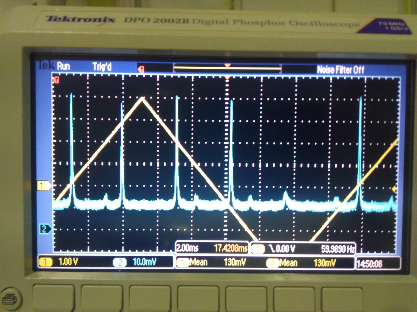
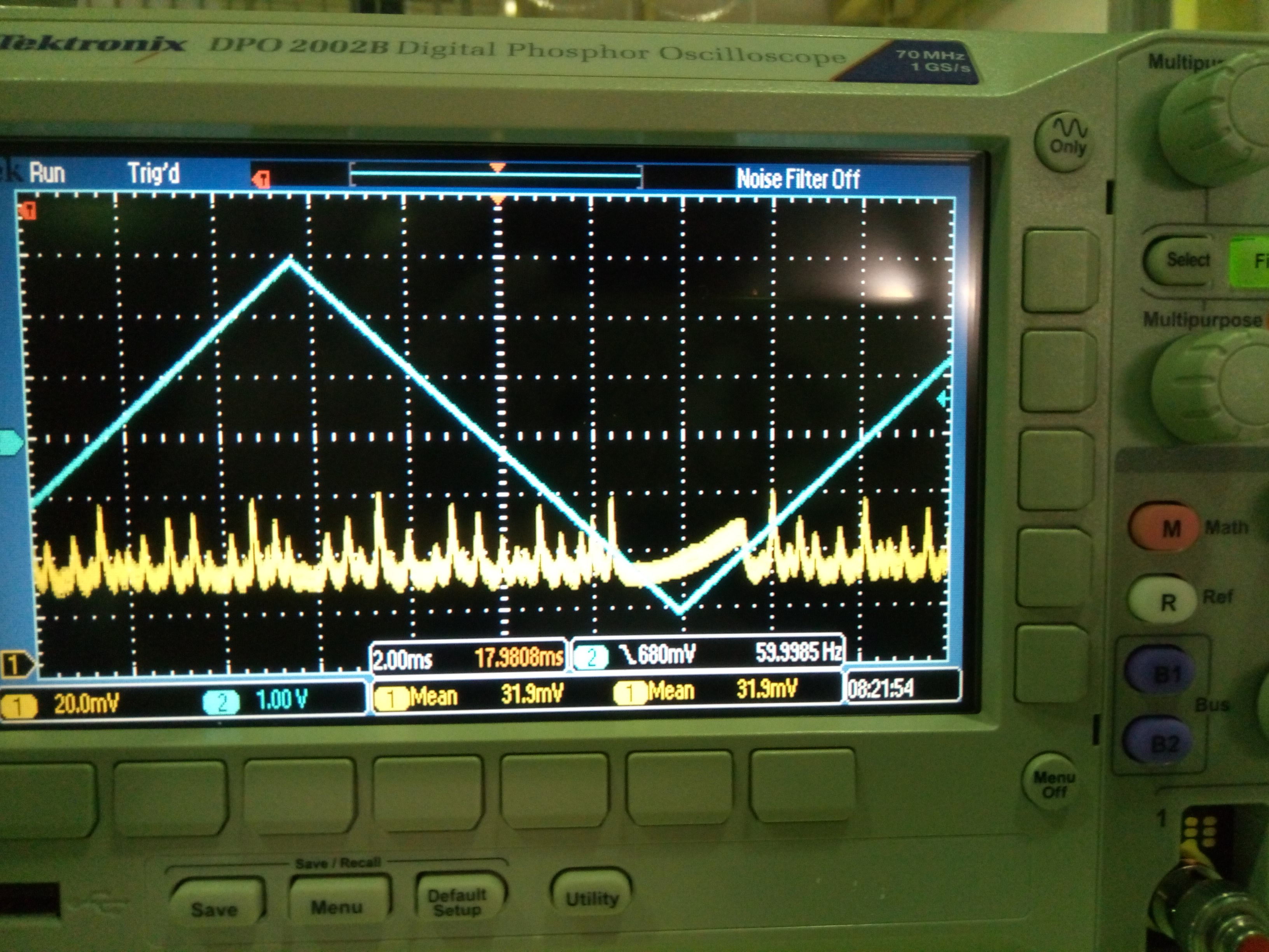
After align OPO with CC beam, I did the alignment with p-pol beam in this morning. As soon as I launch p-pol beam into OPO, I got the attached figure 1.
We know the p-pol power we sent to OPO is only 5.9mW. The OPO choose s-pol to resonant inside the crystal, so we cannot have green if use this p-pol. But I can see signal for infrared on the photodiode. I use this photodiode signal to align the p-pol beam. The steering mirrors I used are the two steering mirrors we put before combinging p-pol and cc. The alignemt result is attached with scan frequency of 60Hz and amplitude of 3Vpp, the signal is shown on the oscilloscope.
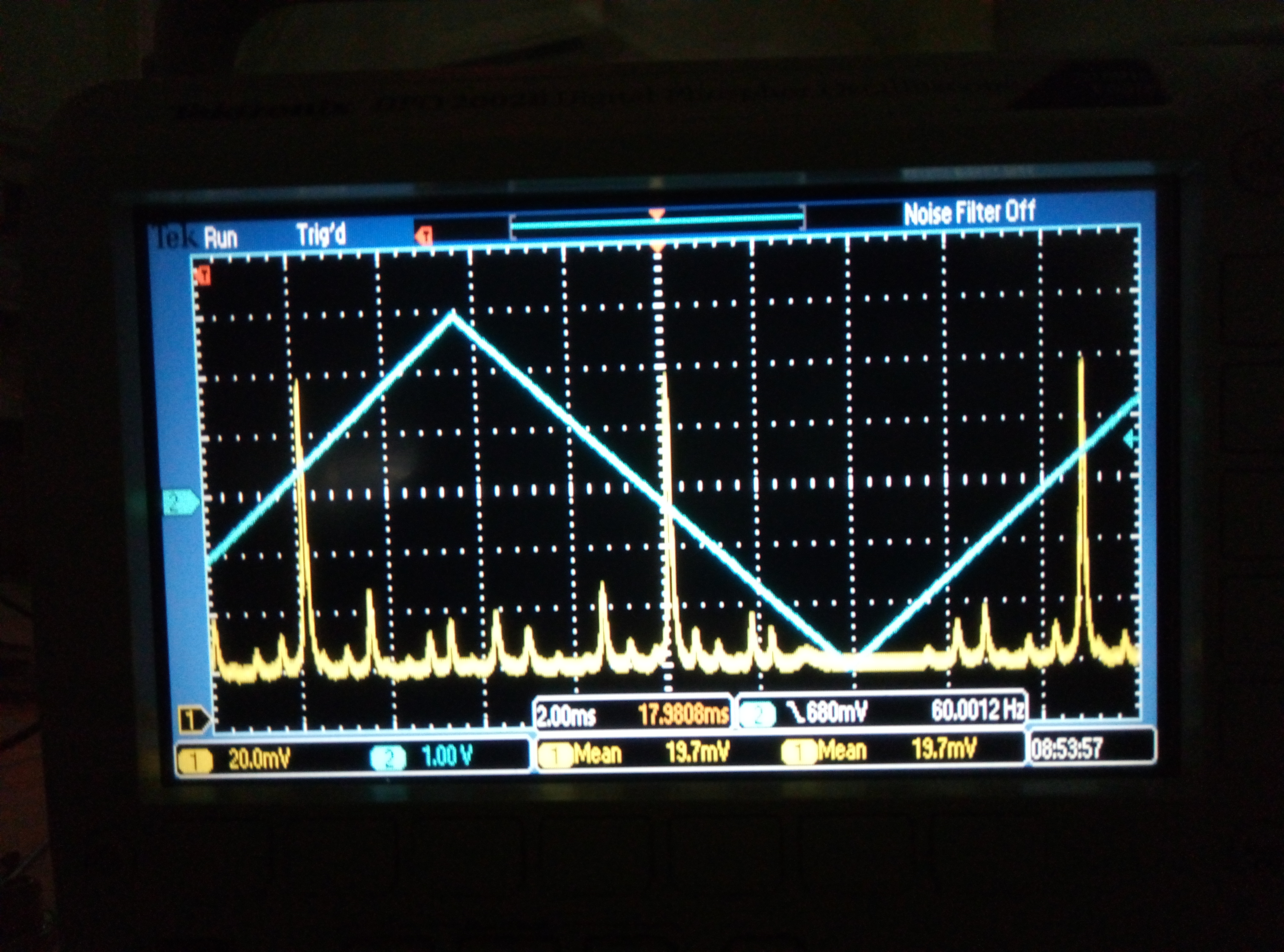
After align them, I measured the power I got for transmission, which is 2.5uW. This is very small so I can use camera directly to see it. I put the camera just in front of photodiode. While scanning the PZT with frequency of 50mHz and 3Vpp ramp signal, I can see the modes I have now. Most of them are pitch higher order modes.
This is the best I can do by moving that two steering mirrors. I still don't know why I cannot improve it anymore.
Participants: Matteo, Yuhang, Eleonora
After aligning the crystal along the beam axis, as reported in entry #959, we put the incoupling mirror and align the whole cavity. The aligment has been optimized by maximazing the TEM00 mode from AUX1(Choerent control laser), while the cavity was scanned driving the piezo of the incoupling mirror. The final result is quite good as it can be seen from Fig 1. At the beginning we observed that two different TEM00 mode were resoanting in the same FSR. We found that this was caused by a laser mode hop and was solved by slighly changing the laser temperature.
We also set the crystal temperature control in order to produce green light. The best value was found to be about 6.740 kOhm, but a further optimization will be done once the cavity is locked. The green light produced was transmitted by the dichroic after the cavity and observed with a camera.
We set the PID gains of the temperature controller to the same values of those used for SHG and the control seems to work fine.
Since my result is different from Marc's result, I did calculation again. I found a mistake in my calculation of ABCD matrixs.
From the calculation point of view, Marc's result is correct.
I will check in actual case to see if the calculation aggres with calculation or not. As I have already mentioned in the meeting, we can see the reflected beam is shaking while the filter cavity is locking. So if they don't agree with the actual case, I think the discrepancy comes from the beam shaking.
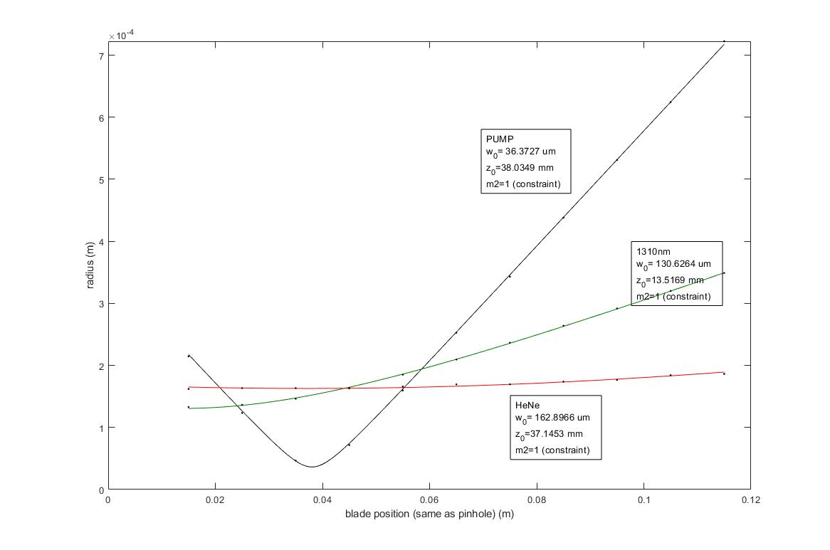
I measured the profile of the three beams. See the attached plot.
In order to match the waists with the crossing point, I have to move the focusing lens of the 1310nm probe forward by about 25mm, but there is no space.
To make space I'm thinking about adding a 90:10 BS (I have a spare) and change the optical path as shown in the draft design attached.
Yesterday 27 Aug we made another try to move end mirror picomotors. We easily recovered the condition when the beam passing through the hole of the second target was reflected by the end mirror on the back of the target, but displaced few cm in yaw from the center. Unfortunately the yaw picomotor is still stuck and we could not recover the alignement. We are probabably left with no other option that opening the chamber.
Participants: Yuhang, Eleonora, Matteo
The transmission found before seems to come from a beam passing through a gap beside the crystal (it was too bright and the reflection was very small and with a strange shape)
Therefore we have restarted the alignment from the beginning. We moved the the 9071 newport Four-Axis Tilt Aligner under the OPO following the usual procedure:
1. Make the reflection superpose the incoming beam
2. Look for a good transmission, always taking care to keep the reflection superposed to the incoming beam.
After may tries we could find a resonably good shaped transmitted beam with a power of 0.047mW. The input power was 210mW. This means the reflectivity is 99.977%, which is in agreement with what we expect.
We put a dichroic mirror after the OPO. The reflection is focused on a photodiode while the trasmission is sent to a camera. Before installing the OPO we have marked the position of the transmitted beam on the screen in order to use it as a reference for the alignment.
Unfortunaltely the tramission after the dichroic mirror is too low and we cannot see any light on the camera, therefore we were not able to use the reference we took for the transmitted beam.
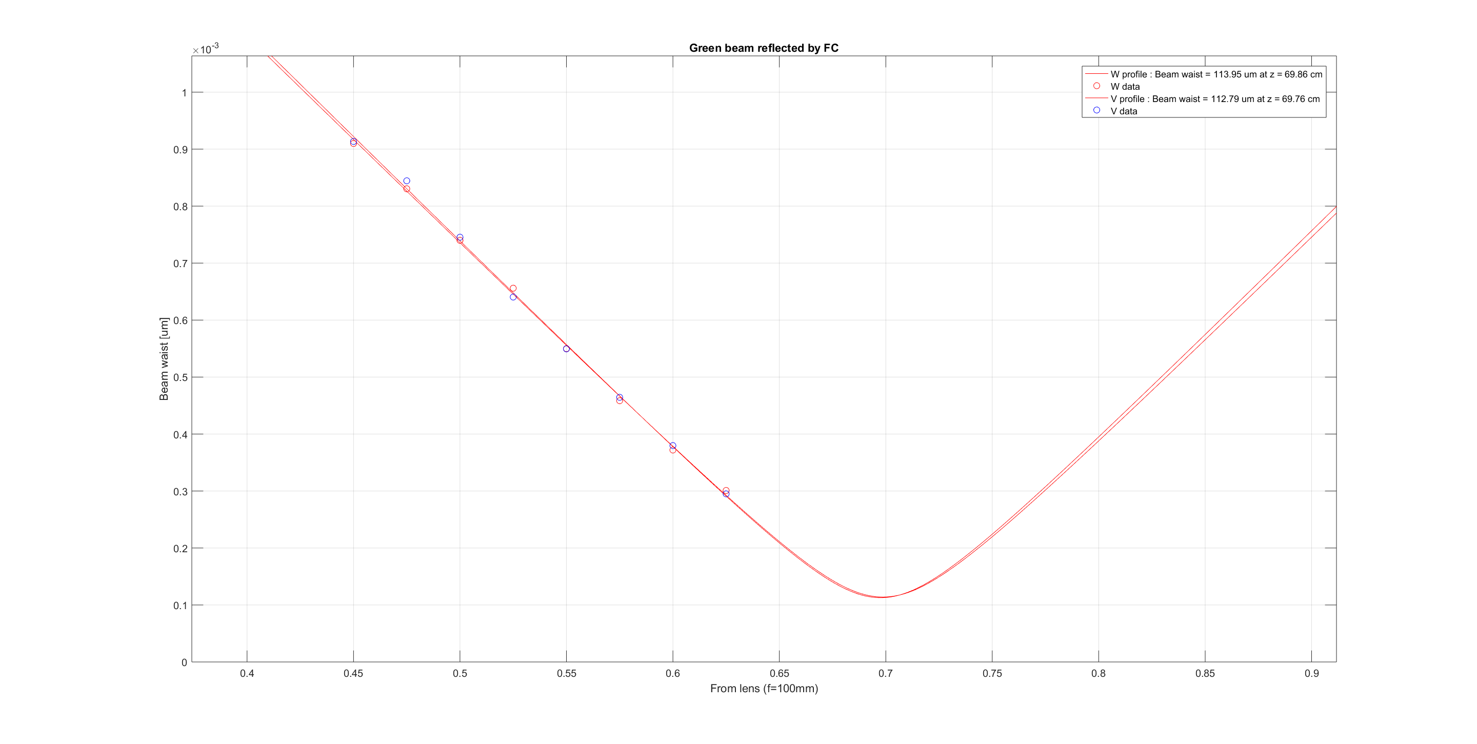
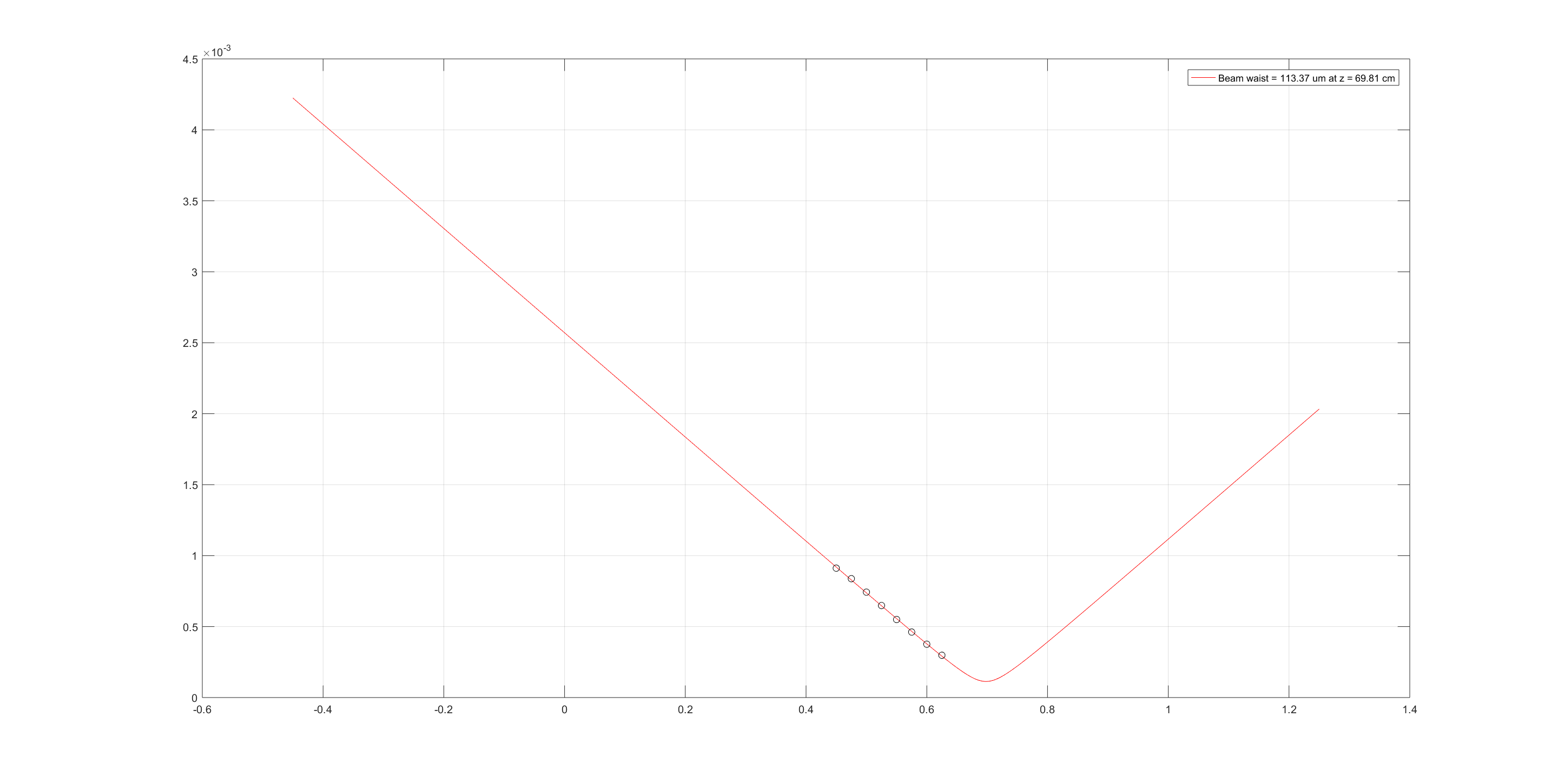
There were few mistakes made on this entry corrected in this one.
Attached to this entry is the proper fit of beam after the lens (previously a wrong wavelength was used for the plot).
The mean profile was used (w0 = 113.37 um 0.6981 m after the f = 100mm lens used for the characterization [lens is 40 cm after the Faraday Isolator])
The beam parameter is the following : w0 = 18.921 um @ 0.1168 m before the lens ie roughly 0.28320m after the faraday isolator.
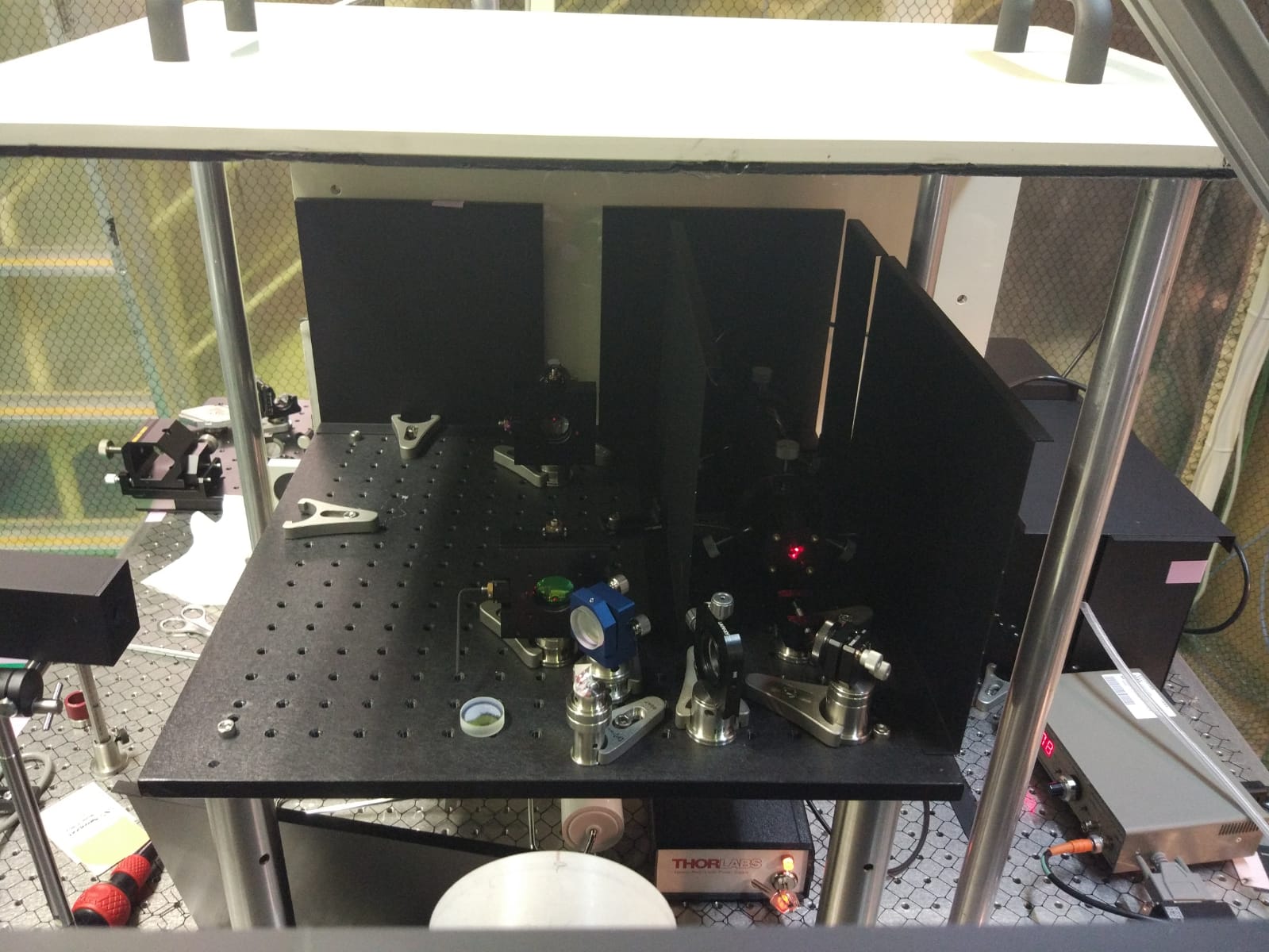
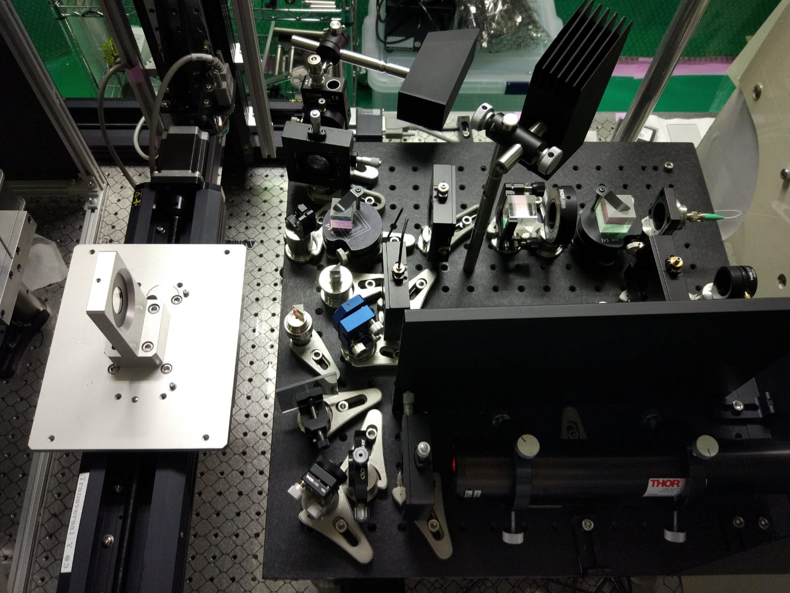
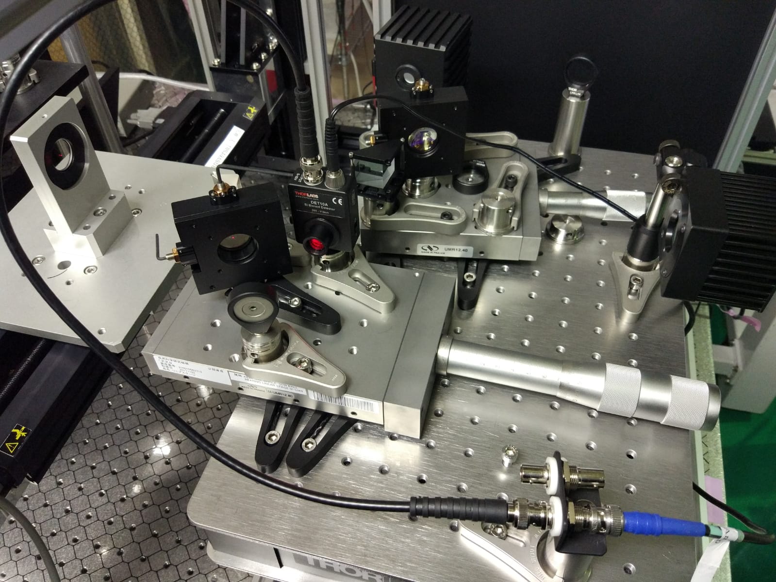
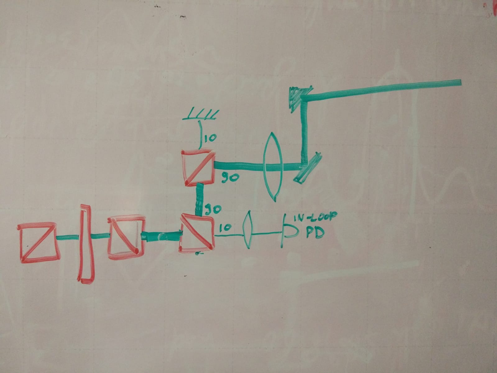
I assembled the components for the optical path of the 1310nm probe:
- Fiber collimator. Output mostly p-polarized.
- Polarizing PBS. Transmission: ~90mW, Reflection ~6mW. The reflection goes to a beam dump.
- Half-Wave Plate
- Polarizing PBS rotated so that the reflection goes upward (to a high power beam dump) and the transmission is s-polarized
- Focusing lens f=300mm
- non-polarizing BS 90(R):10(T).
- Transmitted beam (10%):
- Gold coated mirror
- Converging lens f=50mm
- PD DET10N mounted on a XY lens mount
- Reflected beam (90%)
- Gold coated prism mirror.
- To the crossing point...
Then I aligned the beam to impinge at 0.135rad on the sample at the crossing point. The pump is at 2deg (0.035rad) to avoid the etalon effect on the thin samples, this makes the angle between the 1310nm probe and the pump 0.1rad.
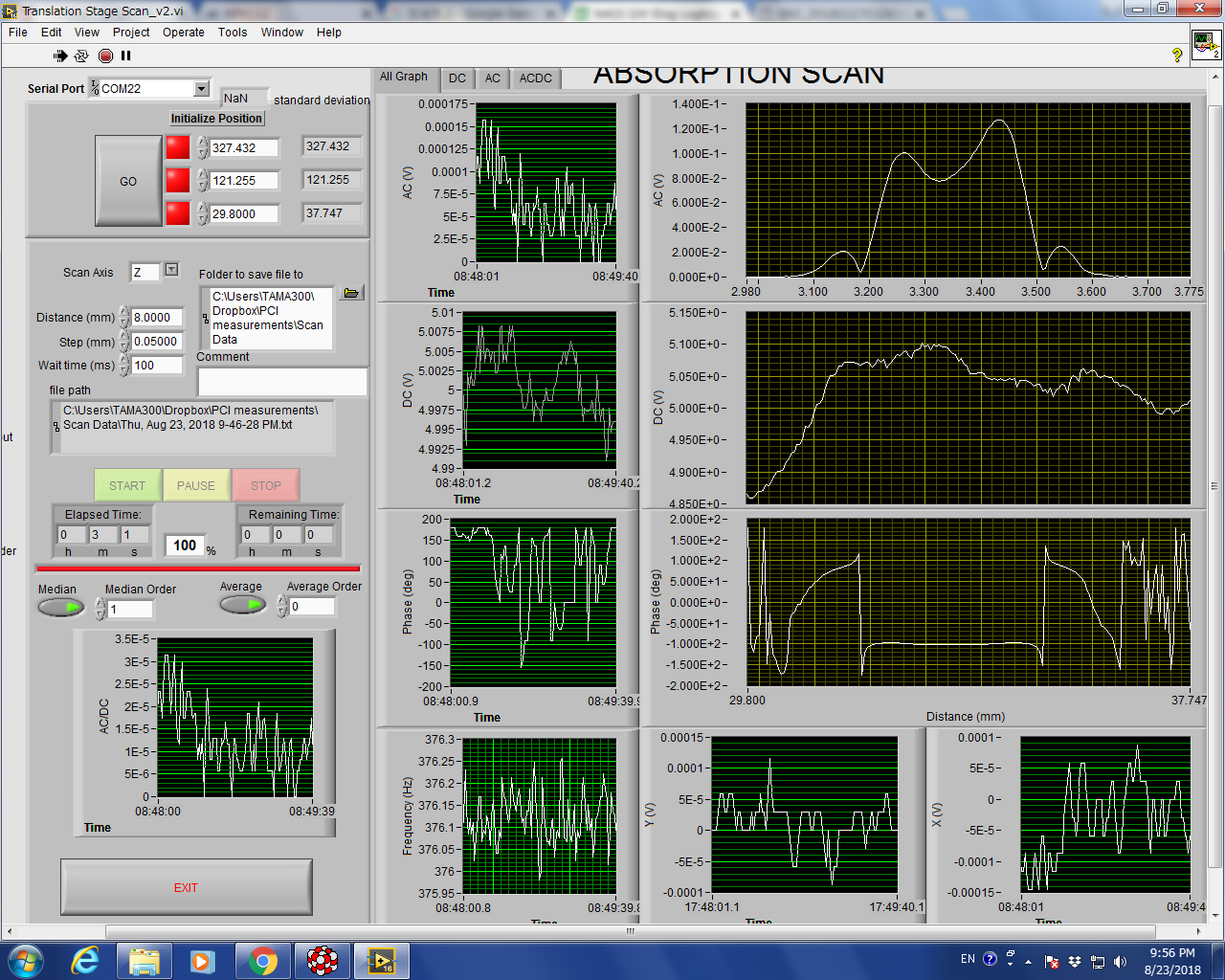
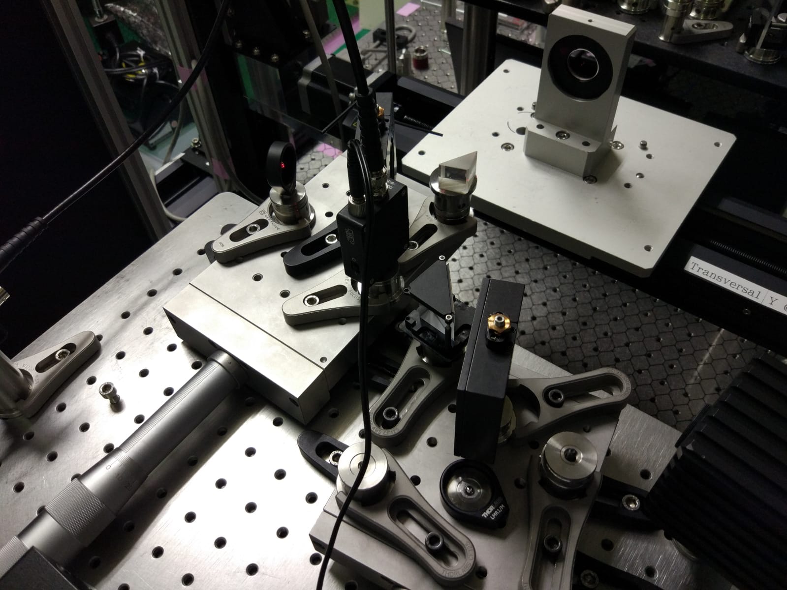
- Aligned the imaging unit. Using a blade at about 1cm from the crossing point. I moved the lens on the imaging unit until I saw a sharp image of the blade at the detector position.
- Using the surface reference sample I aligned the pump with the probe to maximize the signal. Then I maximized the signal finely adjusting the position of the whole imaging unit.
- I noticed that there was some noise (around 300uV in the AC signal) with a constant phase. It came from the chopper vibration. So I put some sound absorbing panels and the noise reduced to about 50uV.
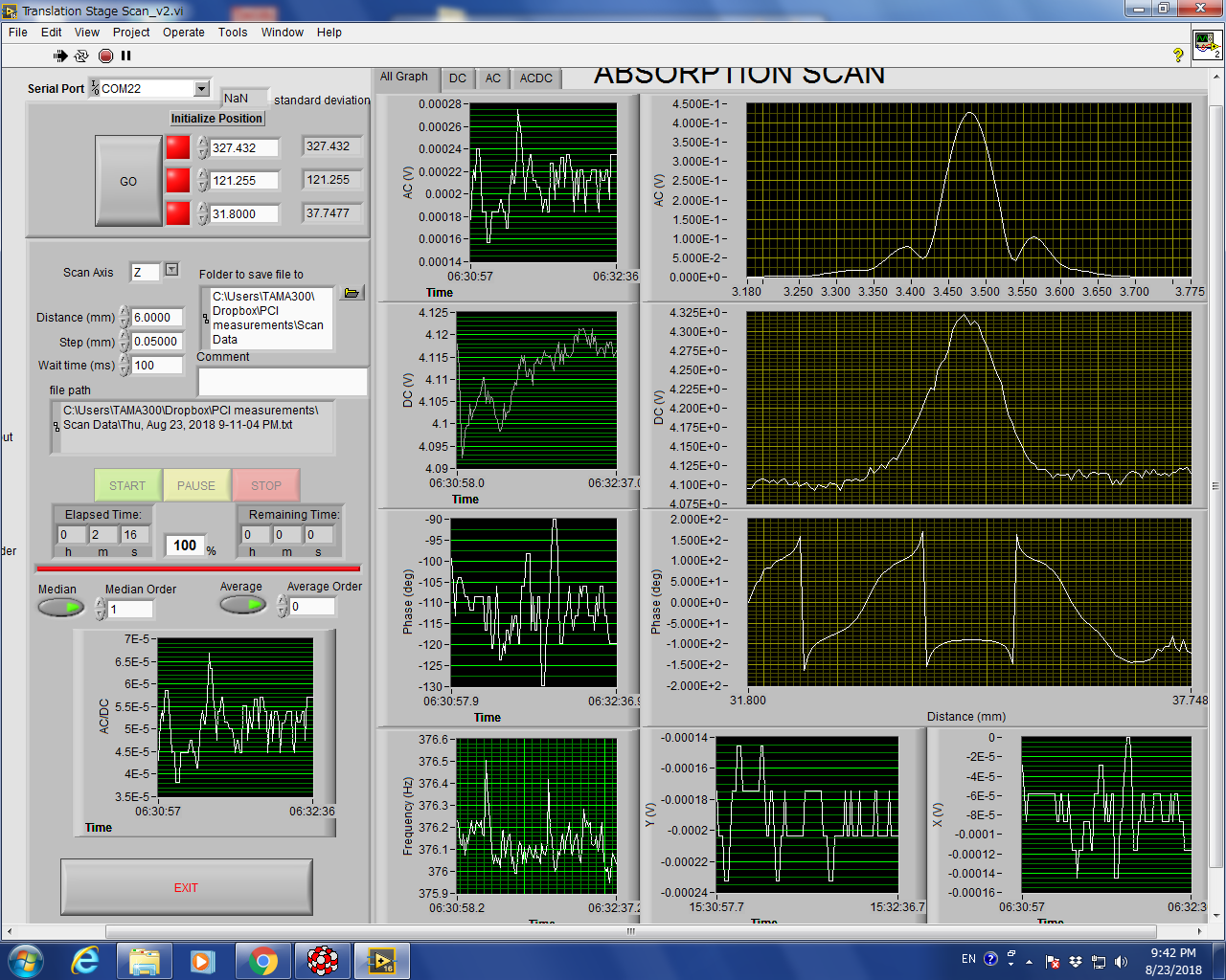
- I made a scan of the bulk reference sample with a pump power of 32mW
- I made a scan of the tama-size sapphire and I got the same absorption as before changing the pump size.
- Compared the scans of the bulk reference sample with small pump and large pump. They give the same value (unexpected) but they have a different shape. To be understood.