Matteo and Yuhang
As reported in elog2289 and elog2302, the demodulated signal from mixer ZX05-1L-S+ has strange behaviors, such as not exactly sinusoidal or strange data distribution. We realized these issues but we didn't know what is the reason.
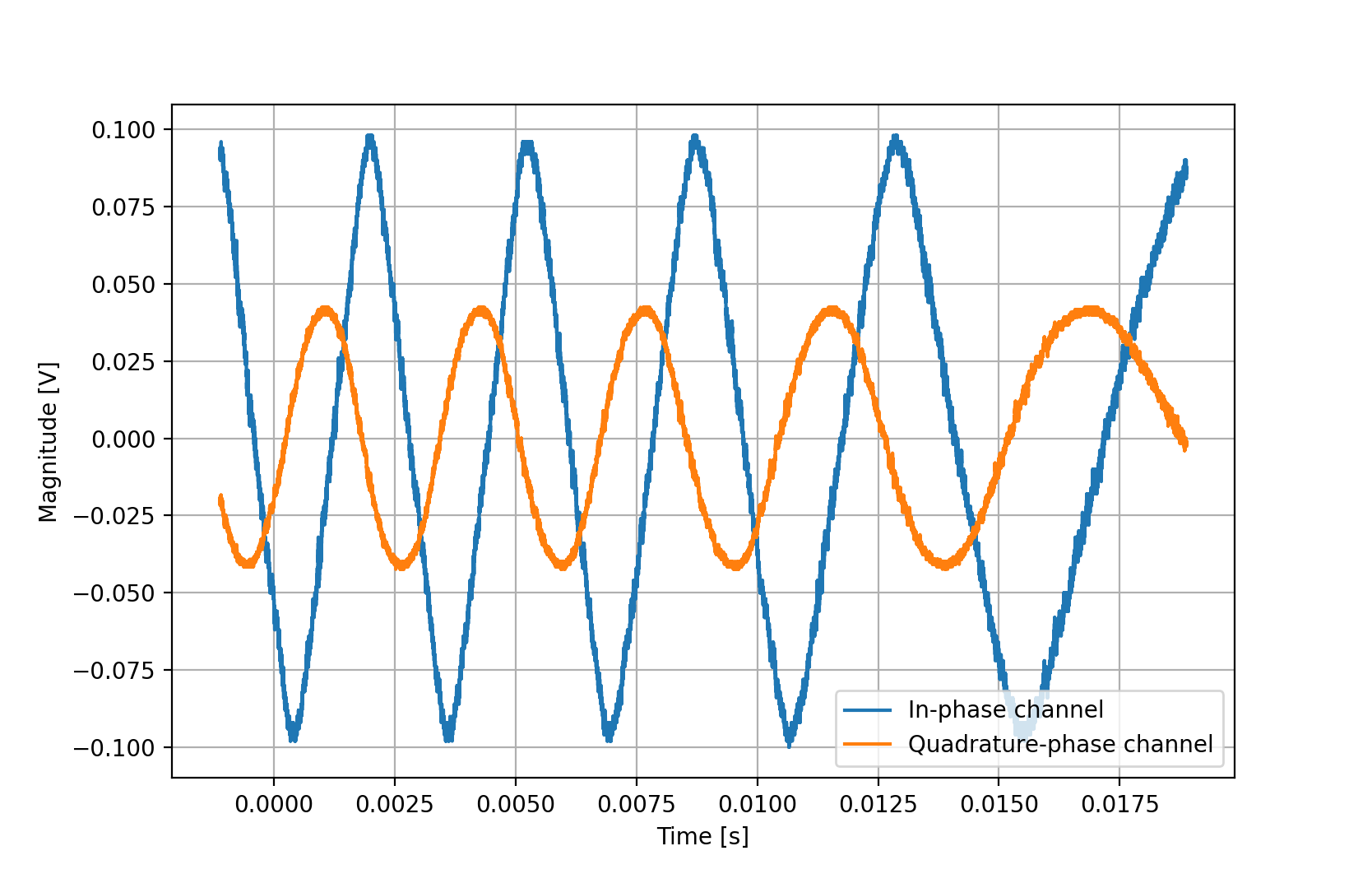
On 2020/22/07, we checked two quadrature-phase signals of CCFC error signal while CC1 phase is scanned more than 2pi. While checking, we found these two quadrature-phase signals were not the same. Attached figure 1 shows these two signals.From this figure, the quadrature-phase signal is quite similar with sinusoidal shape while the in-phase one is quite linear between each maximum and minimum. After observing this difference, we start to investigate what is the difference between these two channels.
Comparison of these two channels:
1. The RF signals come from the same PD, the LOs come from the same channel of DDS3
2. LO signal is splitted by ZMSCQ-2-90, RF signal is splitted by ZFDC-10-1-S+
3. They use the same mixer ZX05-1L-S+ and the same low pass filter SLP-1.9+
The splitting of LO makes one LO ~11dB smaller than the other one (The splitting of LO should give identical output. However, there is difference due to frequency issue.). The splitting of RF makes one RF ~10dB smaller than the other one. (RF signal is about -3dBm before splitting)
In the end, we found the problem comes from LO. We were using ~-6dBm LO, which is smaller than the datasheet requirement. However, in practice, this mixer needs even smaller LO (-12dBm LO is used now).