NAOJ GW Elog Logbook 3.2

It has been a long time that we found CCFC error signal measurement doesn't match well with calculation. Recently, we found that this might be due to an offset, as reported in elog2286.
The CCFC error signal is equation 14/15 in Aritomi paper, which can be written as proportational to sin(a_p-a_m+a0_m-2d_p). Please check details from arxiv:2004.01400.
Here a_p and a_m are the upper and lower sidebands phase change caused by the filter cavity. When the filter cavity has detuning much larger than linewidth (70Hz), a_p-a_m will be close to zero. a0_m is the lower sideband phase change caused by the filter cavity when carrier detuning is optimal. When we change the demodulation phase of CCFC, we add another term phi_d to the sine function.
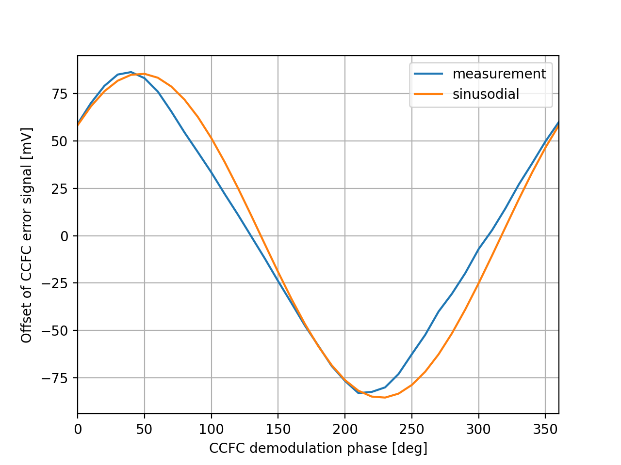
Therefore, in the case that FC is locked and detuned to 1kHz (CC1 locked), the CCFC error signal will be sin(a0_m+phi_d). Since a0_m is a fixed number, we expect to measure a shifted sine wave when scanning phi_d (from 0 to 2pi). For each phi_d, we expect an 'offset' from zero. We got a 'shifted' sine wave from the experiment. The result of this measurement is in the first attached figure. There is also a sinusoidal plotted in this figure. We could see that the measurement matches with sinusoidal. The difference still needs to be investigated (one further check could be a measurement of error bar for each point, the other could be to plot a histogram of measured data)
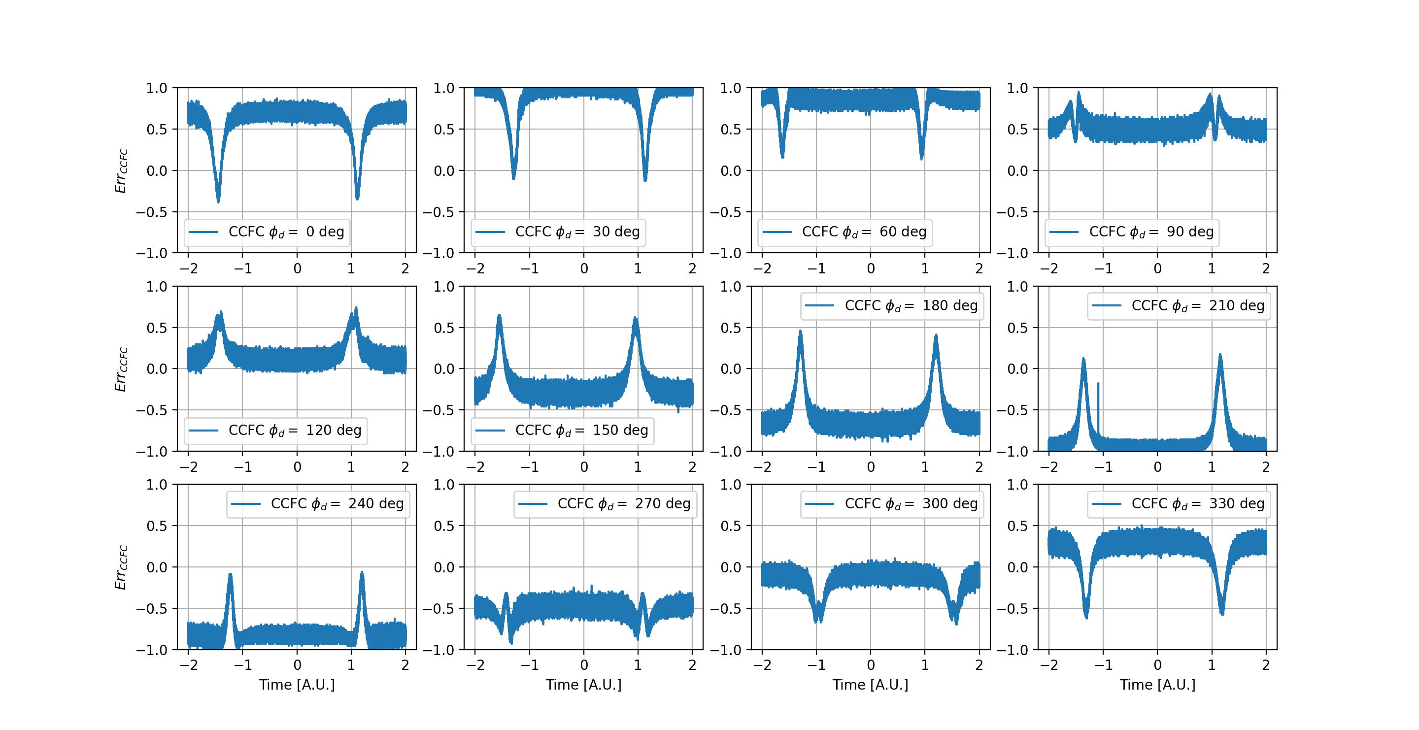
To double-check this expected offset, we performed the filter cavity scan around resonance (CC1 locked, FC locked while AOM scanned). The CCFC error signal for different phi_d is in the attached figure2. If we subtract the measured offset from figure2, we got figure 3. Not surprisingly, all offsets of CCFC error signals were removed. Thus we know this offset agrees with the calculation.
Then the question comes: why we saw a different CCFC error signal in an experiment different from a calculation that is not caused by an offset problem?
If we compare figure 2 with the calculation, we could see that every time the CCSBs cross resonance of the filter cavity, the appeared peak seems to be not deep enough. So we guess the problem is related to how the filter cavity changes the CCSBs phase when they cross resonance.
This not ideal CCSBs phase change could be caused by mode mismatch/misalignment or PLL setting. More investigation is required.
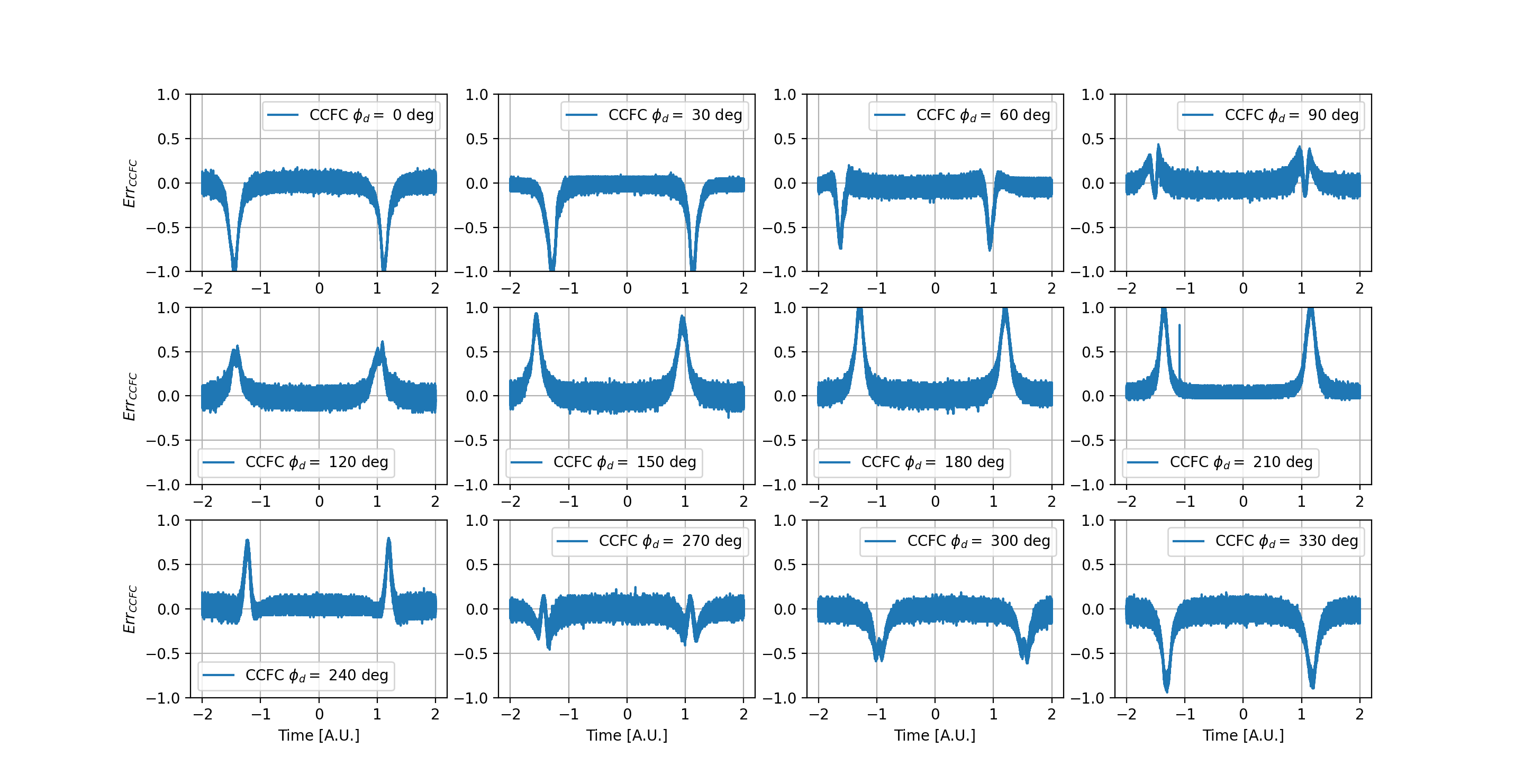
By looking at the normalized offset-removed plots, it seems for different demodulation phase, they have the 'same' peak but just somtimes folded.
If we compare it with calculation, it seems the measured peak is a factor of 2 smaller than calculation.
I checked that for optimal detuning (70Hz), the expected in-phase demodulation CCFC error signal should have normalized offset 0.91.
In this measurement, we got the in-phase demodulation CCFC error signal normalized offset to be about 0.69. I checked that for this normalized offset, the detuning set by PLL will be 43deg.
The calculation is in the attached figure.
By the way, optimal detuning should be 54 Hz. I attached CCFC error signal with optimal detuning. Normalized offset for I phase is 0.81 in the plot.
CCFC error signal with 25 Hz detuning is very similar to the measurement.