[Aritomi, Yuhang, Eleonora]
First we amplified CCFC RF signal by 33.6dB with RF amplifier port which was used for AOM before. We put a DC block (BLK-89-S+) before the RF amplification. The result is as follows.
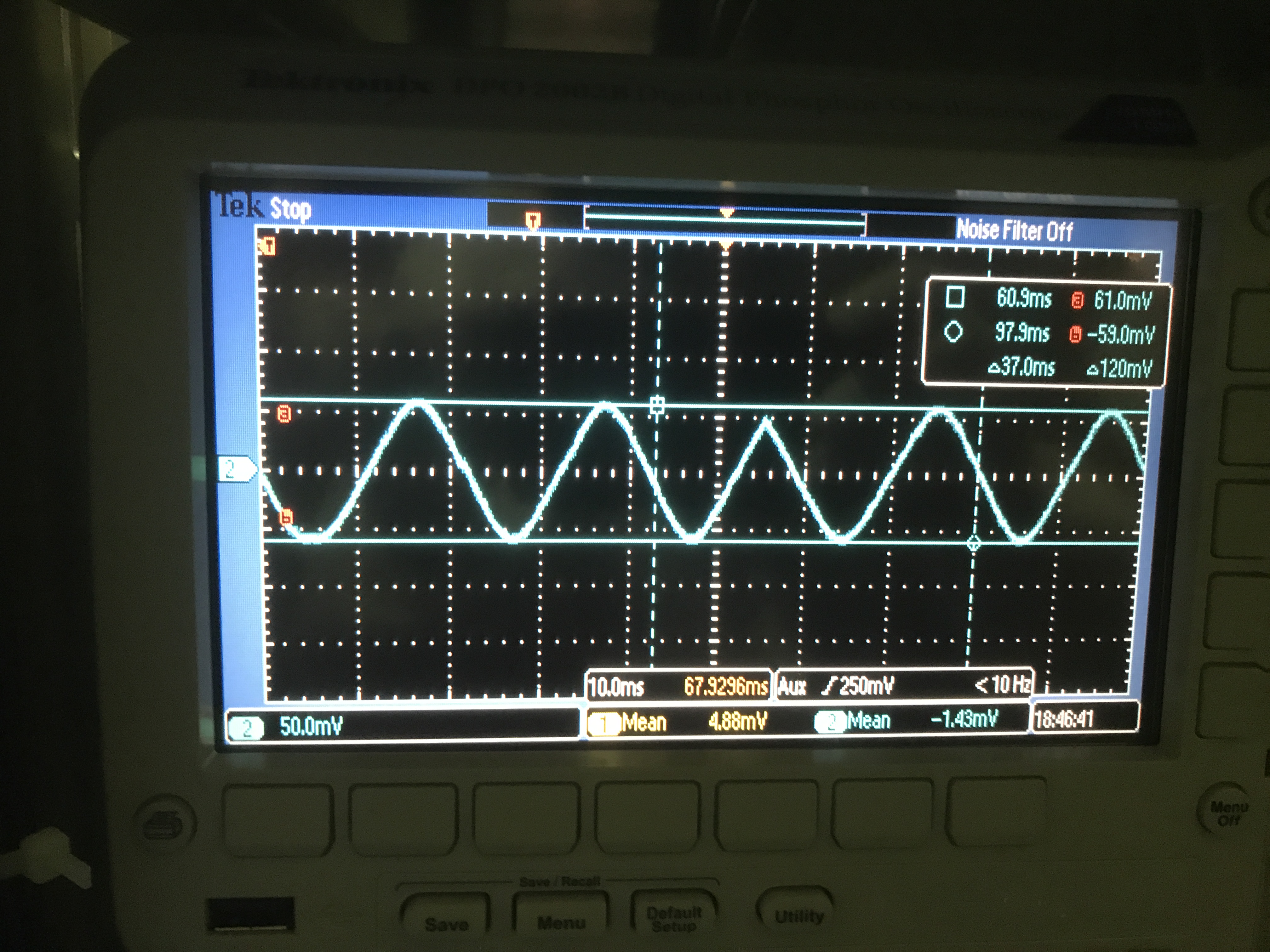
We demodulated it with a new mixer and measured CCFC signal when CC1 is scanned and CCSB are off resonance. The signal is 120 mVpp and no offset (Pic. 1).
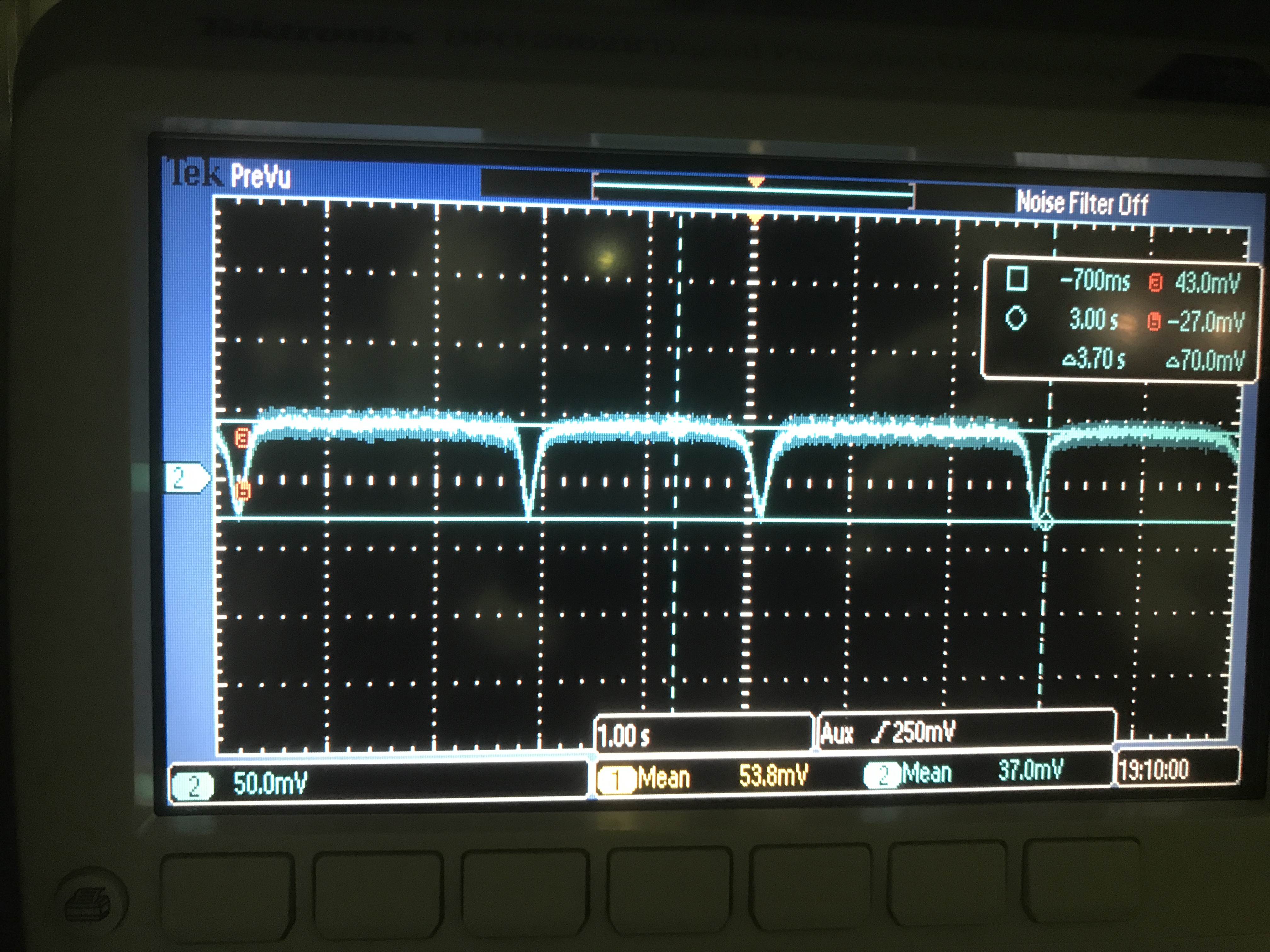
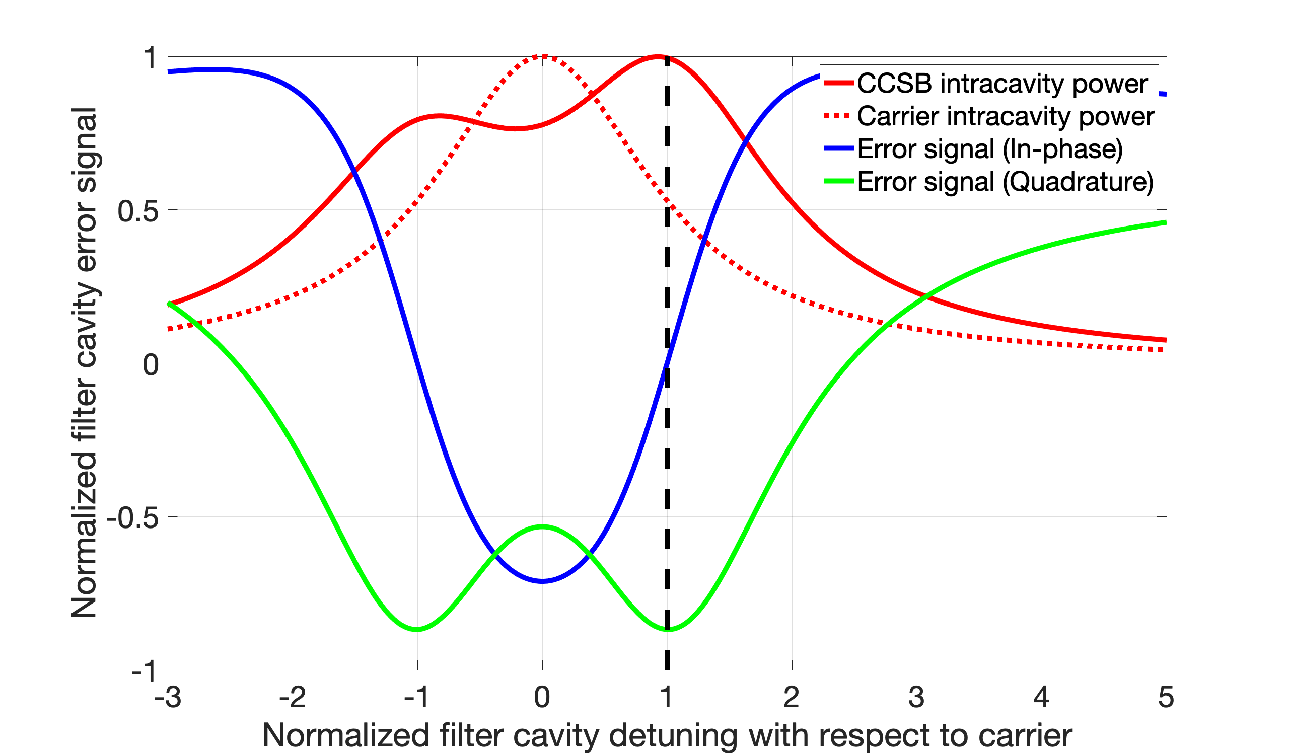
Then we locked CC1 (CC1 gain: 0.5 for 56 mW green) and changed PLL setting as before. Carrier and CC AOM frequency are as follows. Frequency difference between carrier and CC is 60Hz which is good. We scanned AOM around CC resonance. The CCFC error signal seems I phase (Pic. 2). Theoretical CCFC error signal with 56mW of green is Pic. 3.
We tried to change the CCFC demodulation phase by changing 14MHz DDS phase, but CCFC error signal didn't change. Since changing 14MHz DDS phase changes both CC1 LO and CCFC LO, this may cancel out the phase change.
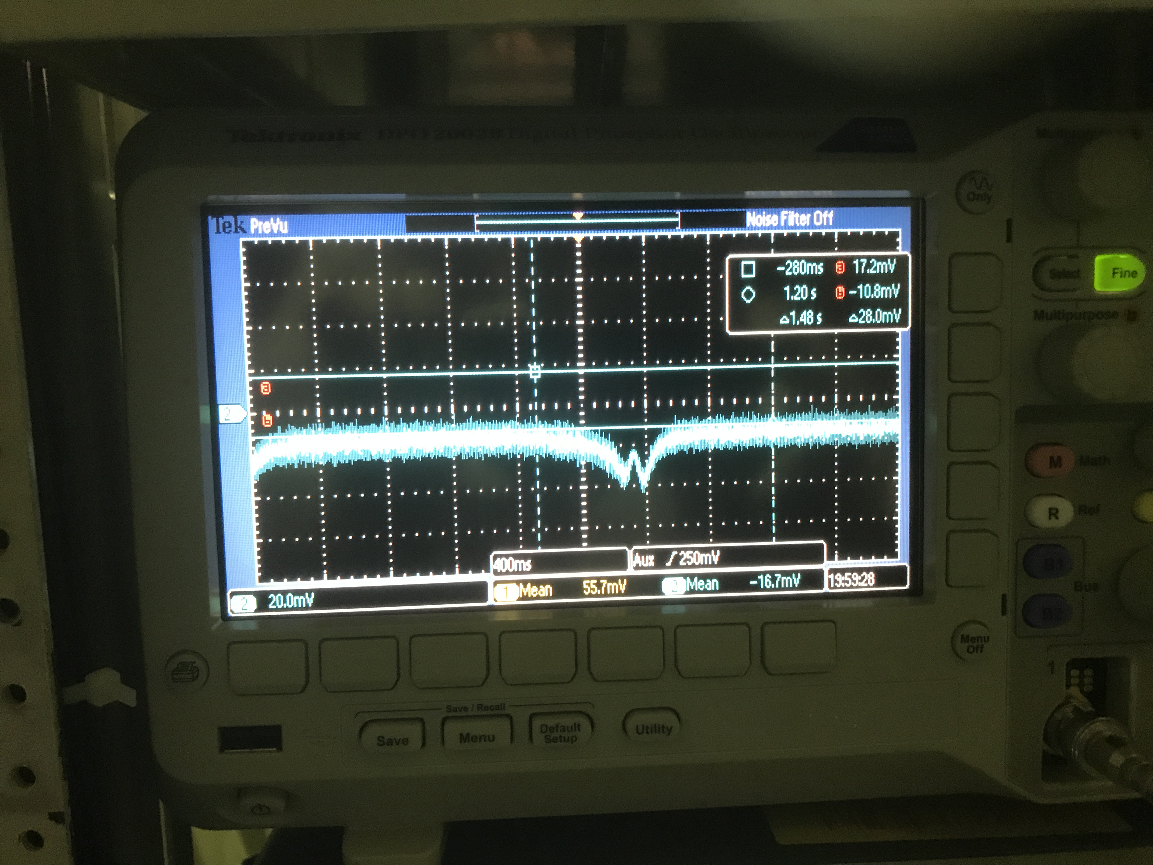
So we tried to change the CCFC LO demodulation phase only by adding a 2.5 m cable to CCFC LO. Then CCFC error signal became Q phase (Pic. 4) although it is not crossing 0. Theoretically 90deg phase delay of 14MHz signal should be 3.5 m (lambda/4 = c/sqrt(2.3)/14MHz/4) where 2.3 is the relative permittivity of polyethylene. There is a bit difference between theory and experiment. We need a phase shifter for fine tuning of CCFC demodulation phase.
Anyway it seems we can use this error signal to lock FC.