NAOJ GW Elog Logbook 3.2

[Aritomi, Yuhang, Eleonora]
To make one of CCSB on resonance inside filter cavity, we set CC PLL frequency 6.997043MHz following previous measurement. We also changed 14MHz and 21MHz accordingly in DDS board.
Binary number is as follows.
| Frequency (MHz) | Binary number |
| 6.99704303 | 11 10010101 00011101 11001110 |
| 13.99408607 | 111 00101010 00111011 10011100 |
| 20.99112910 | 1010 10111111 01011001 01101010 |
Then we split CC1 LO (14MHz) into 50:50 with Z99SC-62-S+ to use it for demodulation of CCFC, but CC1 was unstable due to low SNR. Therefore we amplified CC1 LO by 33dB and attenuated by 20dB before splitting. Since output of DDS board is -6.5dBm, CC1 and CCFC LO is -6.5+33-20-3 = 3.5dBm. Then CC1 locked stably.
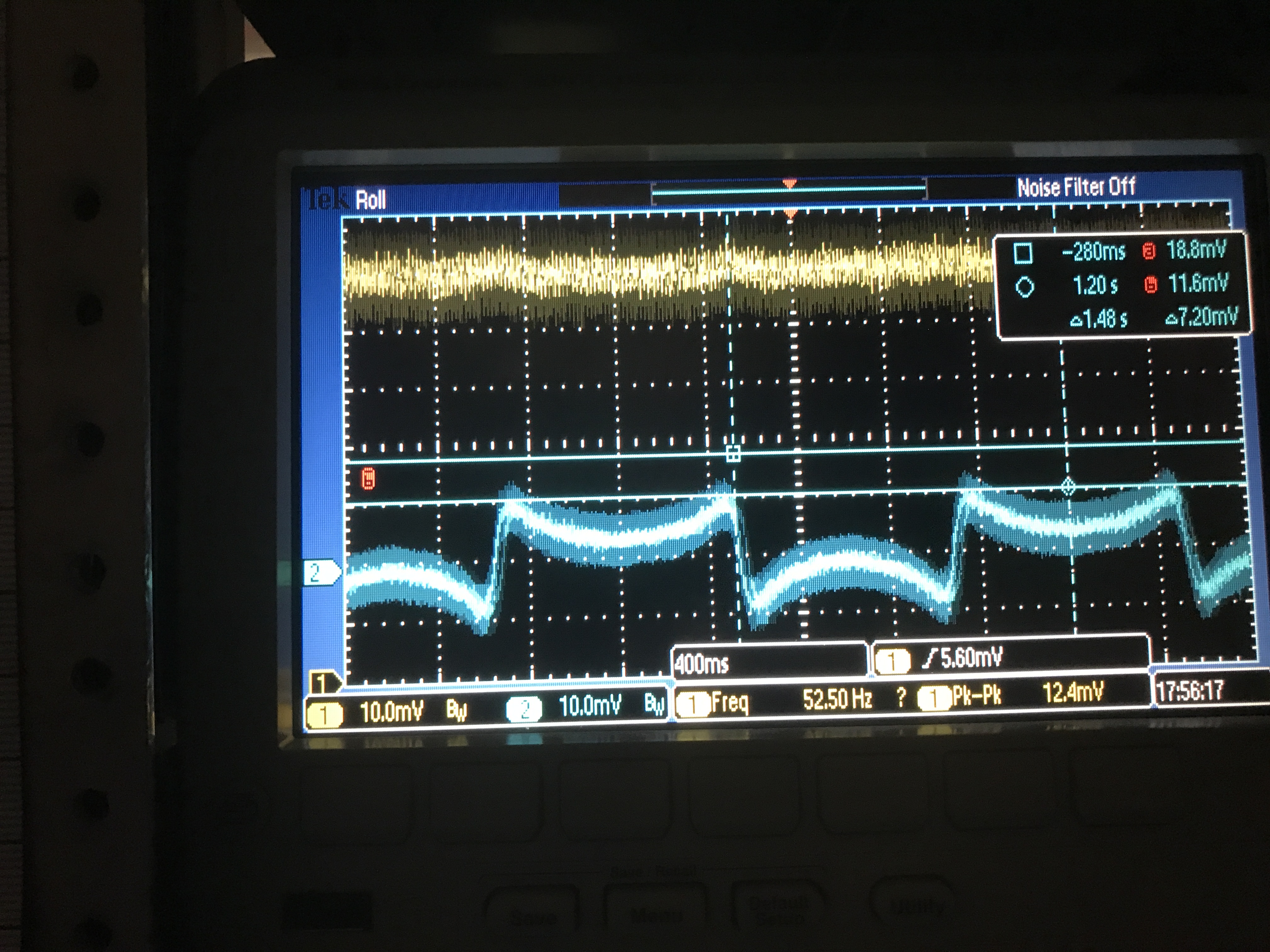
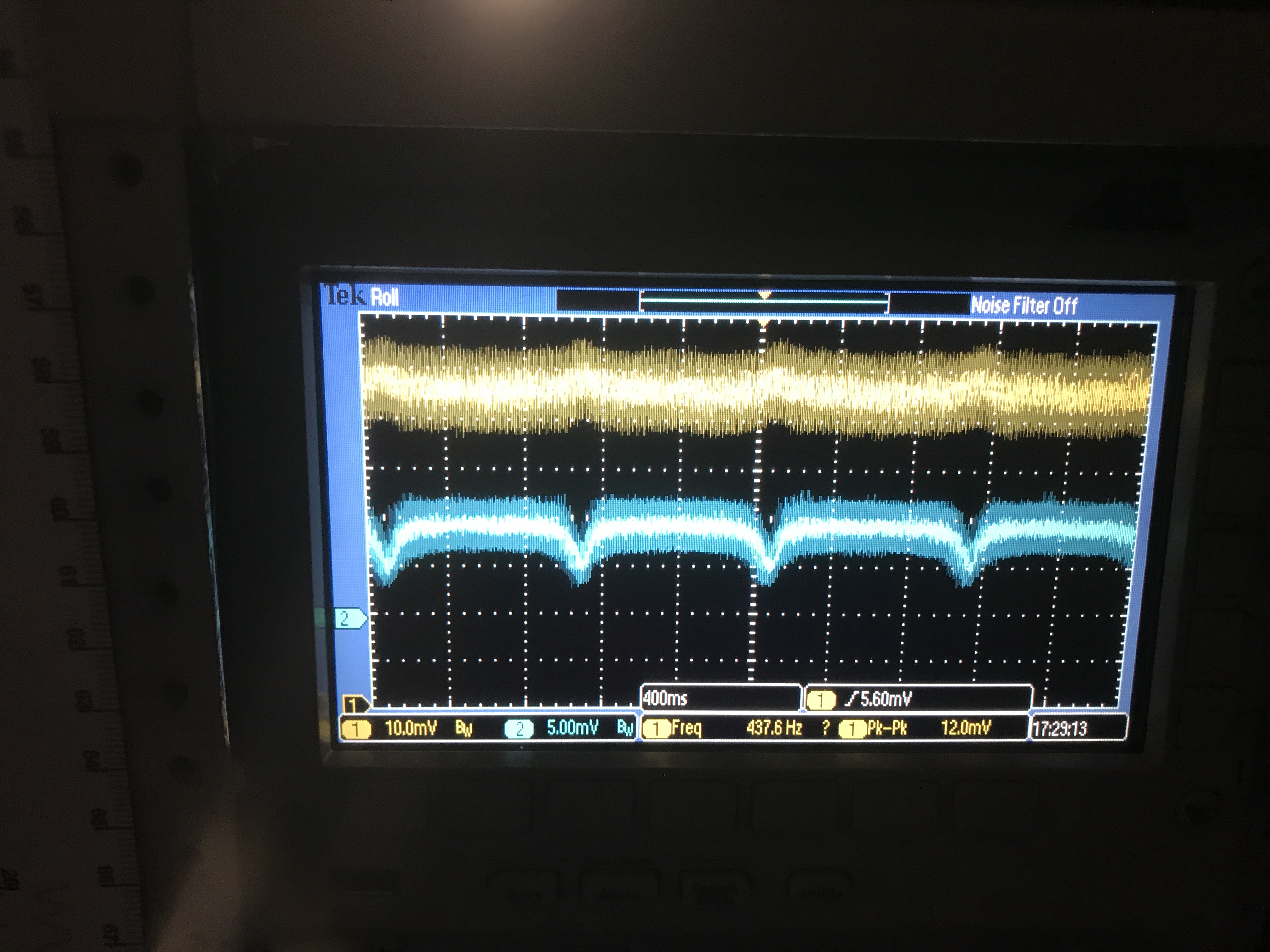
We set CC PLL 7MHz as usual and scanned AOM around one of CC resonance while other CC sideband was off resonance. CCFC error signal was shown in Pic. 1 (Channel 1: IR transmission, Channel 2: CCFC error signal). It seems like usual PDH signal. Then we set CC PLL 6.99704303MHz and found CC resonance at 109.03598MHz while carrier is 109.03584MHz which means carrier is detuned by 109.03598-109.03584 = 140Hz. CCFC error signal was shown in Pic. 2. The error signal was just a dip and didn't change by demodulation phase.