NAOJ GW Elog Logbook 3.2
Displaying report 1-1 of 1.
YuhangZhao - 22:47, Thursday 21 December 2017 (617)
abnormal behavior of local control, beam position, determination of PDH phase
This week we installed steps for our optical bench, then we did some arrangement around the bench. It includes the rearrangement of equipments and cables.
We know for PDH control, the local oscillator phase and signal phase must match. But the cable length can affect this phase. So after changing cables, we need to set the phase of signal generator again.
Firstly, we need to close the loop for local control to make the light beam interferes well inside the cavity. However, I found the local control goes oscillation even with the previous value. The previous value means the value we used for locking yesterday. I should mention this abnormal case happened the day before yesterday.
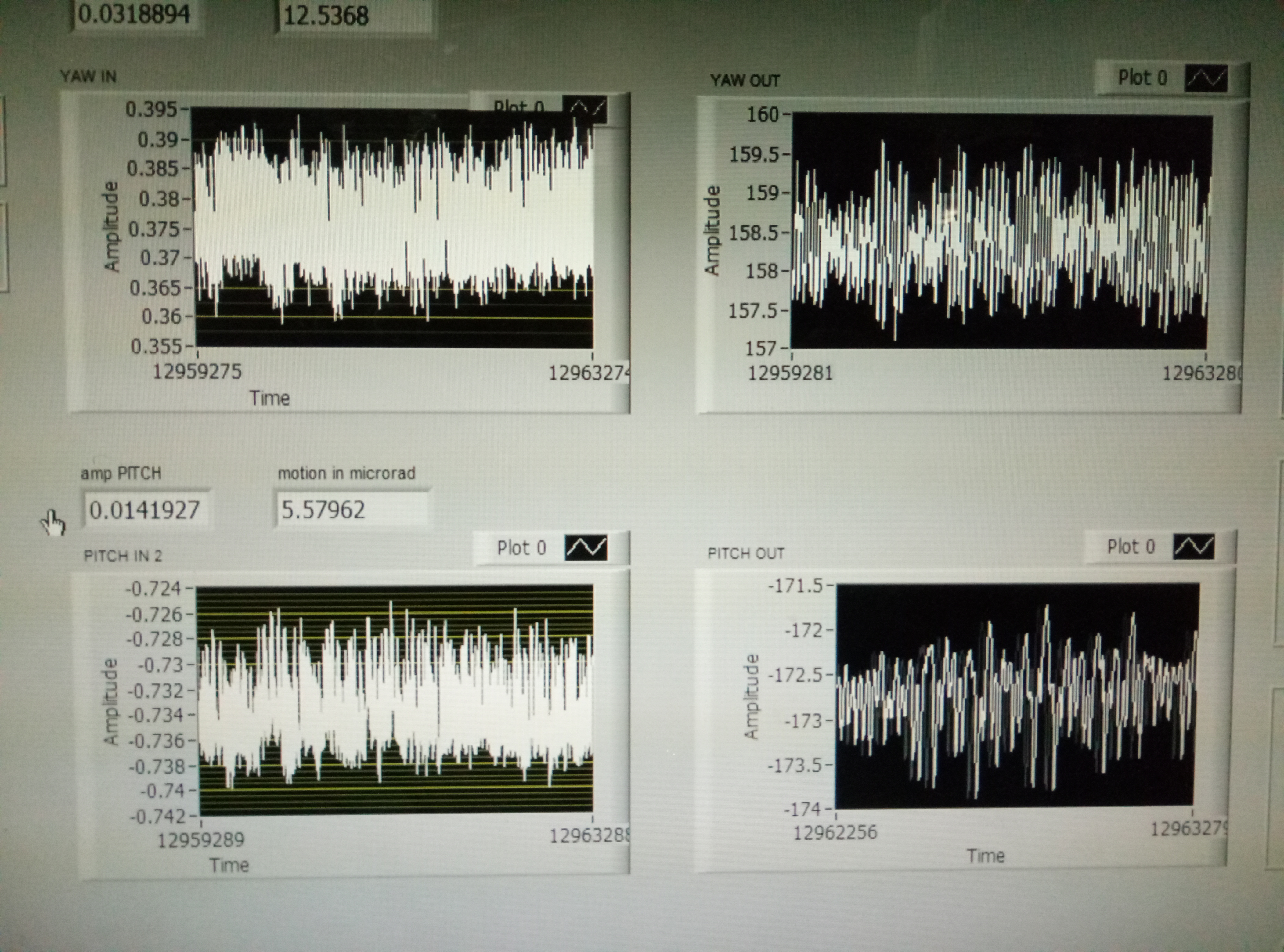
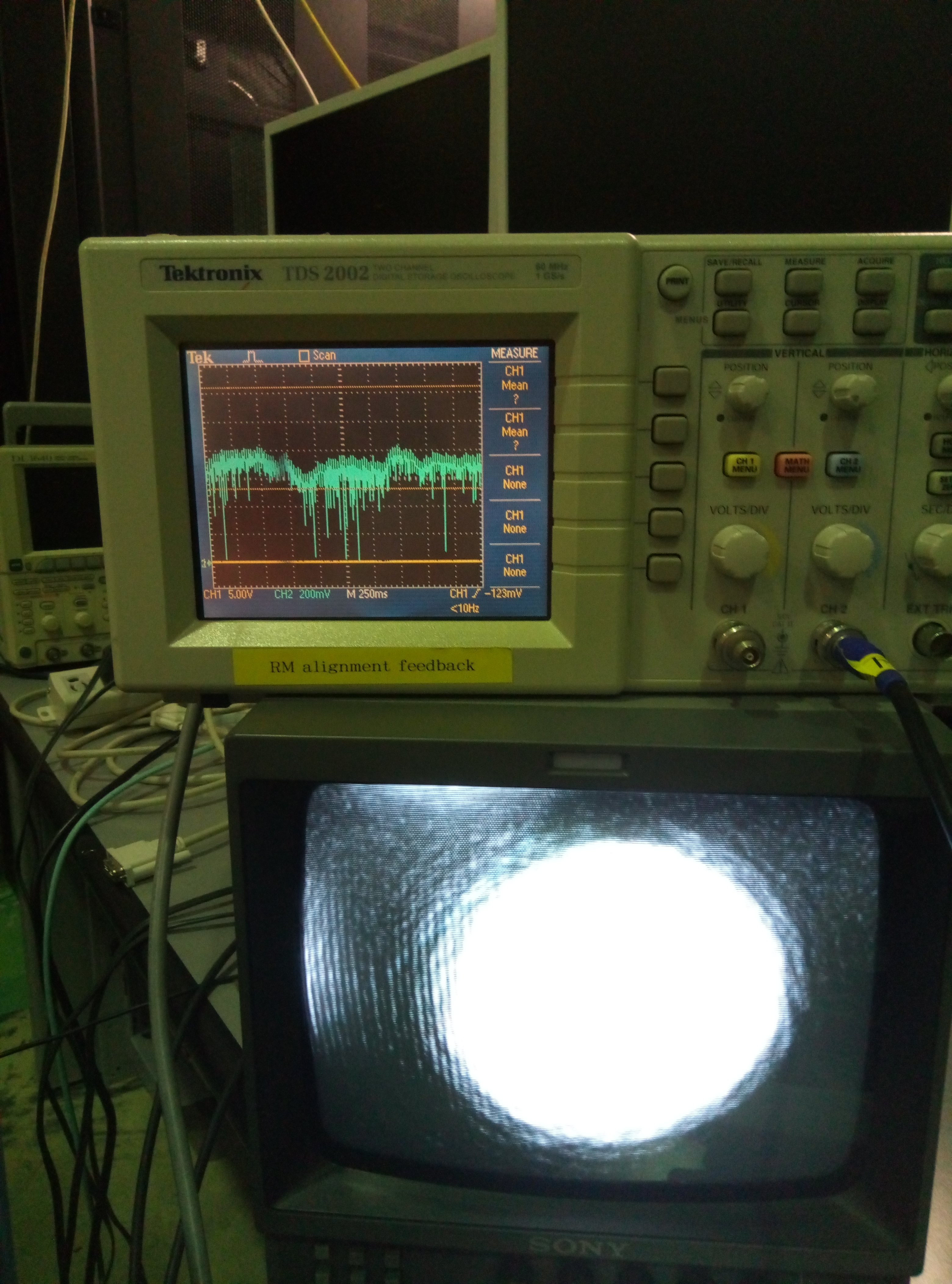
After a very long time of adjusting, I found the the local can be fairly stable while the output of local is large(Fig 1). I adjusted it a little and make the output much smaller(but it is still around 40). Then I could find the beam through the end room camera.
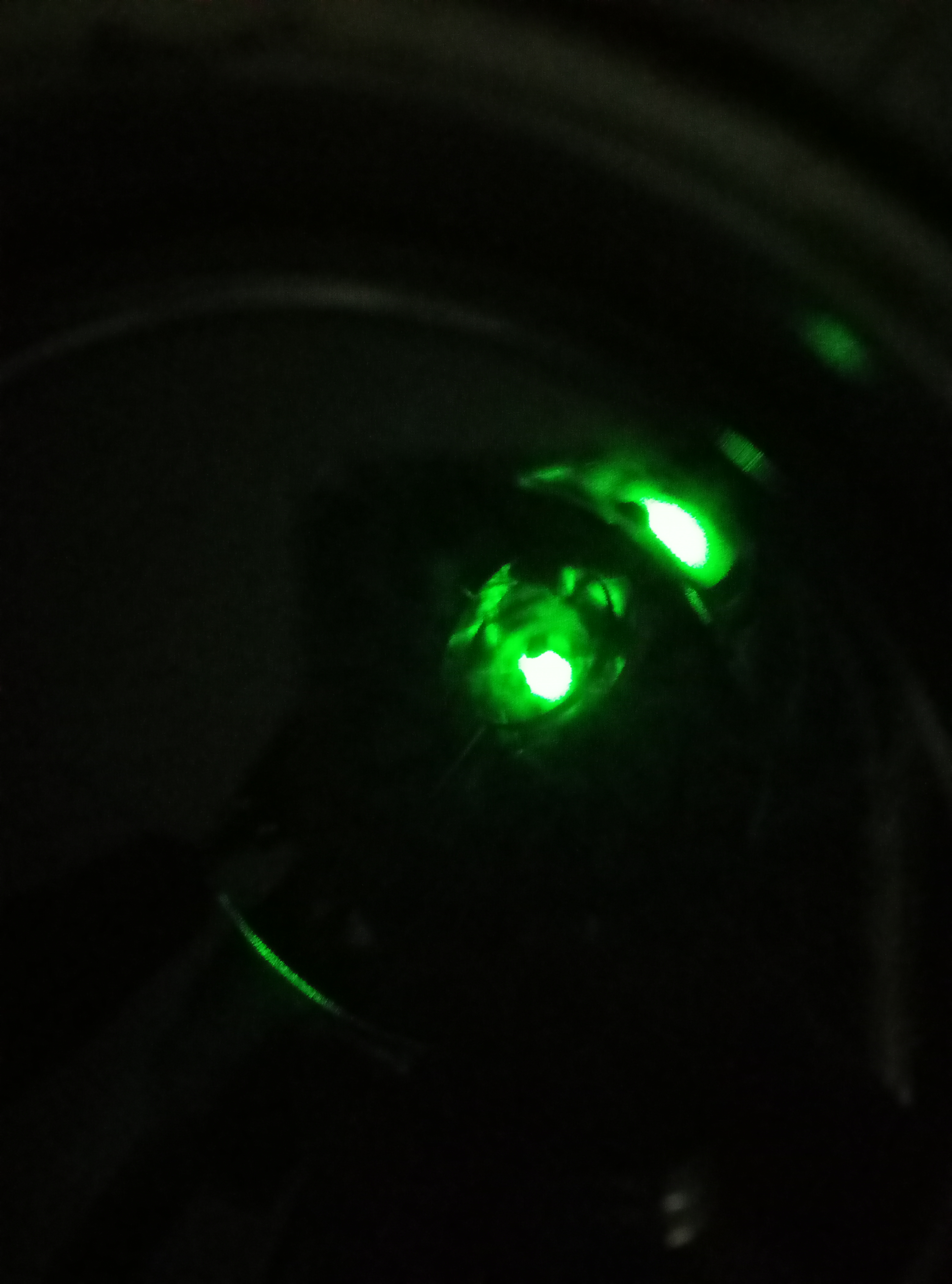
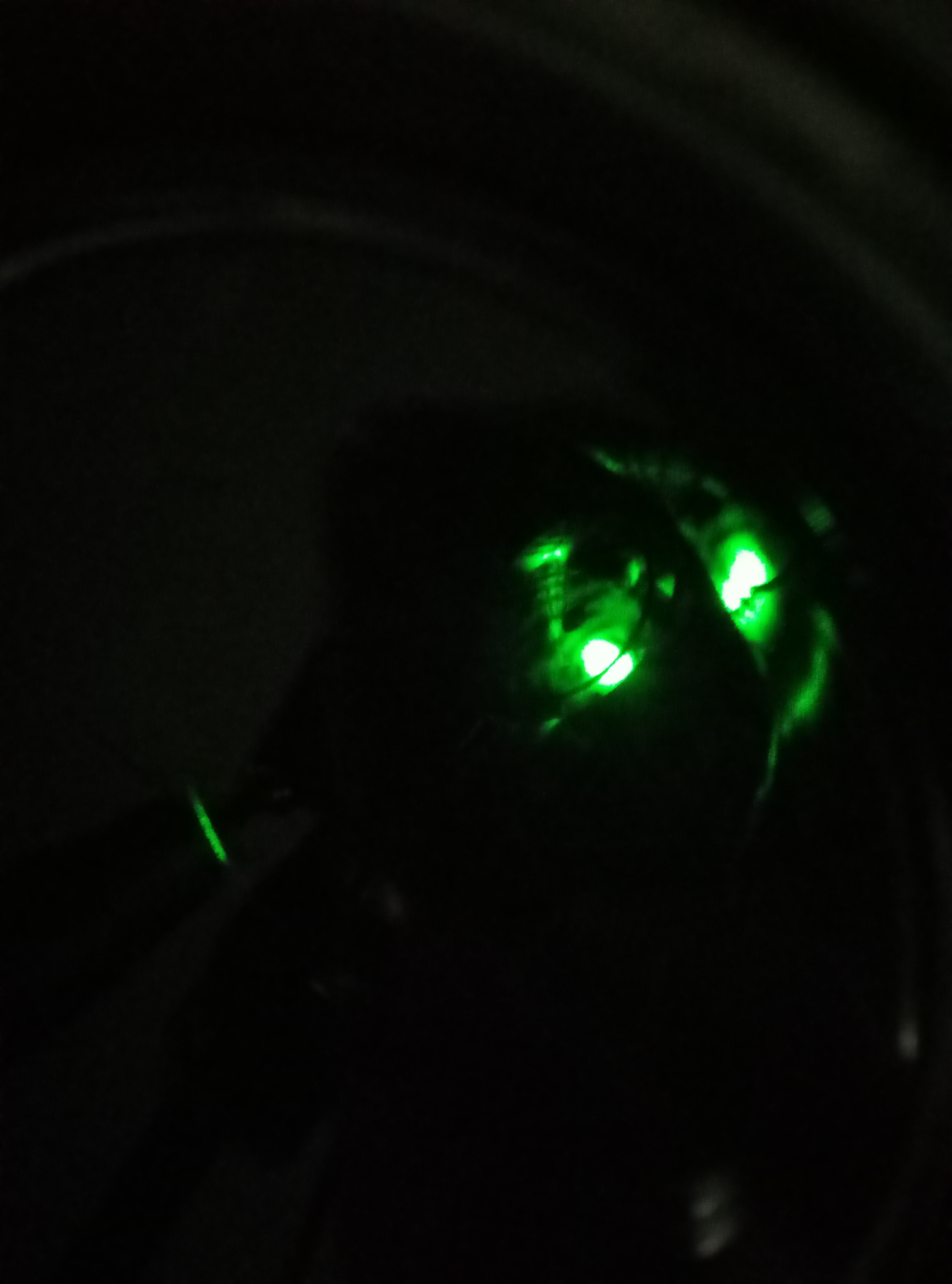
Secondly, I took the photo of beam on the first iris(Fig 2,3) and the second iris(Fig 4).
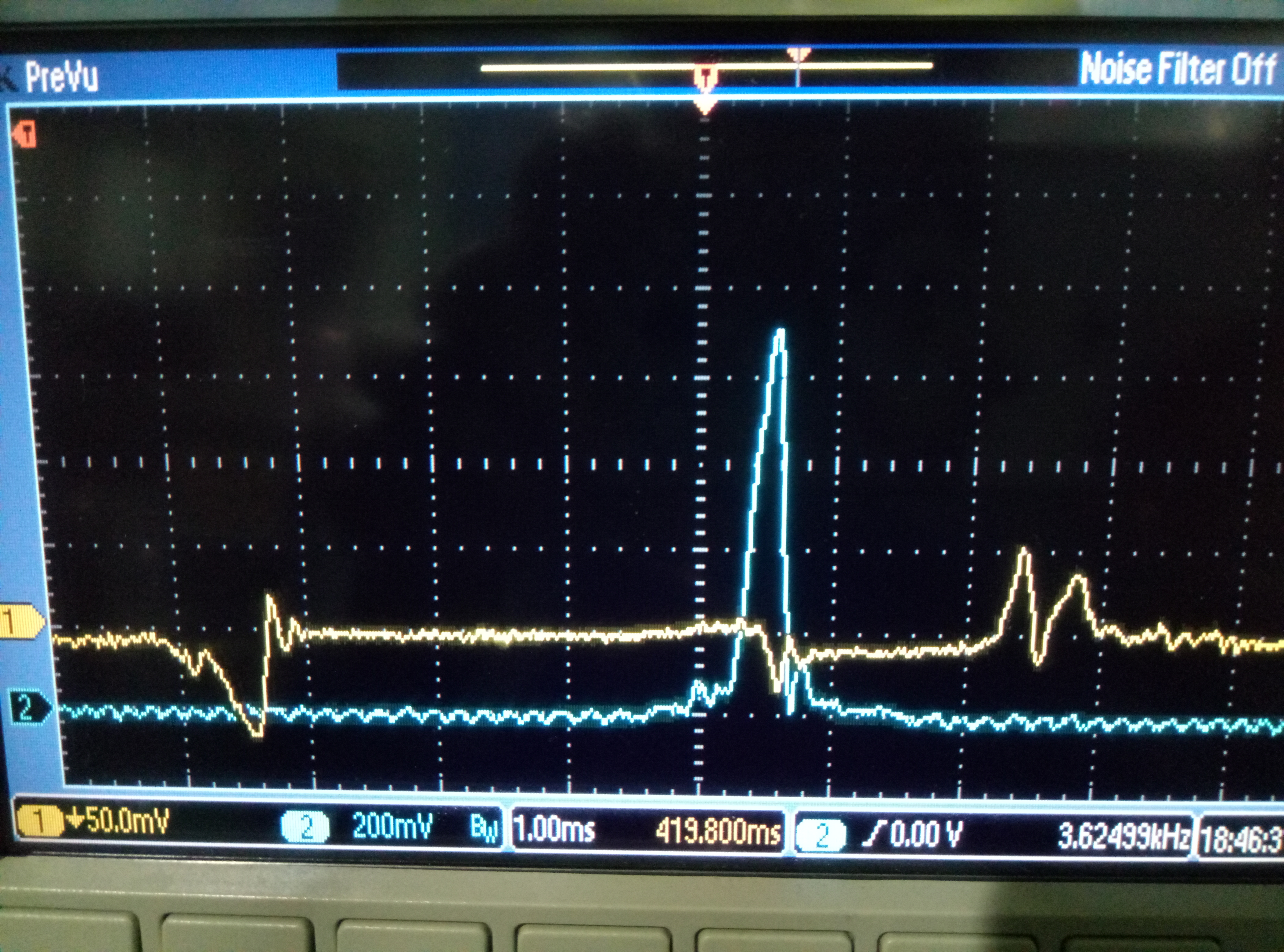
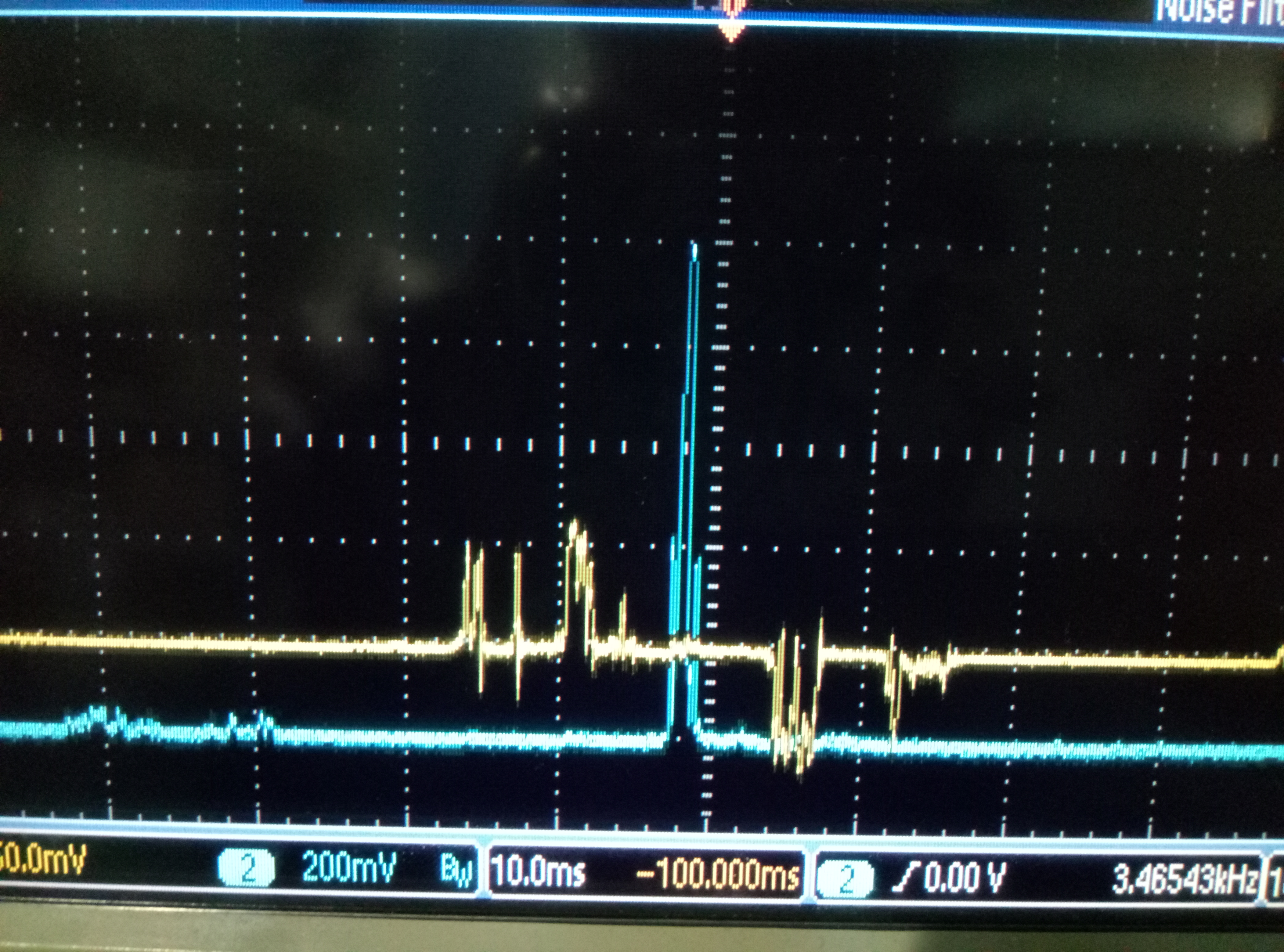
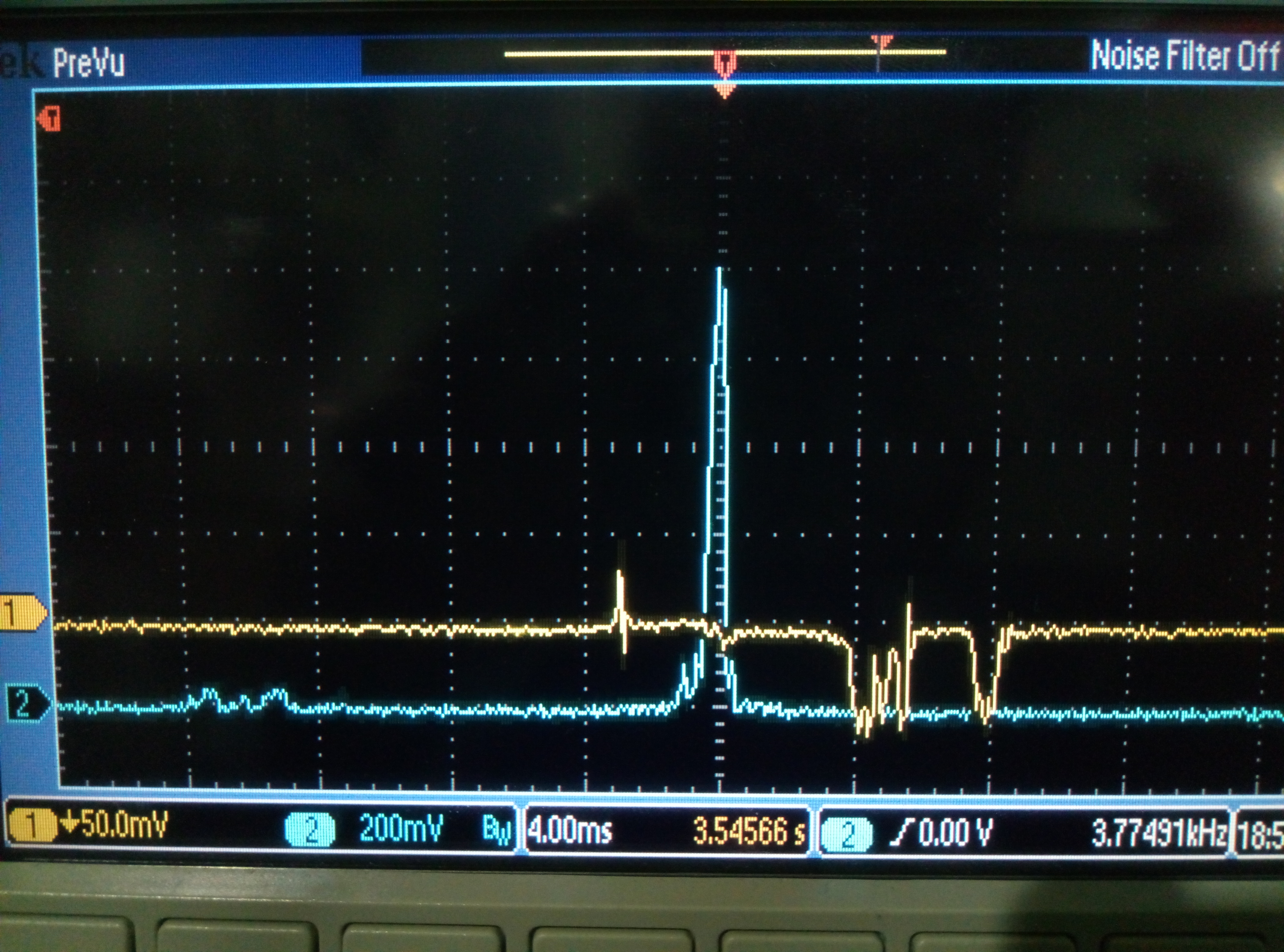
Thirdly, I went to set the PDH phase. I set different value to see how the error signal looks like. I took three pictures(Fig 5,6,7) for this processes. We can deduce from them the worst case should between 80 and 90 degrees. So I set the phase as 175 degrees.
Finally, I found the transmitted signal decreases from 1V to 0.6V(Fig 8). And I found this is not caused by the SHG. Now the SHG locking is pretty pretty good! This is caused by the bad local control. The position of mirror drifts away fast. However, this maybe also caused by the large output of local control. Besides, I and Matteo measured the TF of BS pitch. Matteo said it is not a good control system according to this TF. So the local control definitely should be improved.
We know for PDH control, the local oscillator phase and signal phase must match. But the cable length can affect this phase. So after changing cables, we need to set the phase of signal generator again.
Firstly, we need to close the loop for local control to make the light beam interferes well inside the cavity. However, I found the local control goes oscillation even with the previous value. The previous value means the value we used for locking yesterday. I should mention this abnormal case happened the day before yesterday.
After a very long time of adjusting, I found the the local can be fairly stable while the output of local is large(Fig 1). I adjusted it a little and make the output much smaller(but it is still around 40). Then I could find the beam through the end room camera.
Secondly, I took the photo of beam on the first iris(Fig 2,3) and the second iris(Fig 4).
Thirdly, I went to set the PDH phase. I set different value to see how the error signal looks like. I took three pictures(Fig 5,6,7) for this processes. We can deduce from them the worst case should between 80 and 90 degrees. So I set the phase as 175 degrees.
Finally, I found the transmitted signal decreases from 1V to 0.6V(Fig 8). And I found this is not caused by the SHG. Now the SHG locking is pretty pretty good! This is caused by the bad local control. The position of mirror drifts away fast. However, this maybe also caused by the large output of local control. Besides, I and Matteo measured the TF of BS pitch. Matteo said it is not a good control system according to this TF. So the local control definitely should be improved.
Images attached to this report
Comments related to this report
A comment on the local controls large output: the voltage range at the output of the DAC is +/- 10 Volts. So If the correction signal is out of this range (as in the case of picture 1) the output is saturating and the control loop is likely not to be working properly (as can be seen from the large RMS in picture1).
More in general, looking at the error singnal, it seems to me that we are still affected by the "spikes issue". It could be useful to compare the open loop rms with the reference values in the absence of spikes.