NAOJ GW Elog Logbook 3.2
Displaying report 1-1 of 1.
Matteo Barsuglia - 22:40, Sunday 02 July 2017 (521)
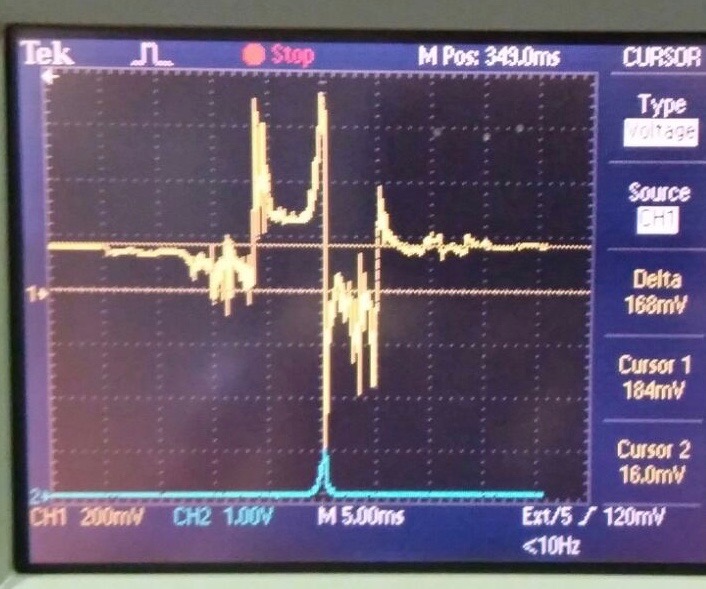
Offset in the filter cavity reflected signal
We observe that the PDH filter cavity signal has an offset of ~ 170 mV. See picture.
The offset is present even when the 78 MHz signal sent to the EO modulator is swithed off (and the 78 MHz sent to the local oscillator is ON). When both signals are OFF, we see a slowly varying offset between 200 mV and -200 mV, which also have an higher frequency oscillation. To be investigated.
Images attached to this report
Comments related to this report
[I report about the investigations done by Pierre Prat about the offset in the error signal]
The mixers ideally have a zero offset when the LO and RF signals are in quadrature, if it is not exactly the case, they can have an offset that can be a few mV, varying with the frequency of LO.
We saw this afternoon that the 1.9 MHz low-pass filter (LBP1.9) was not terminated by a 50 Ohms as it should be. We had an offset of the order of 200mV on the output monitor EPS1. By charging the filter with a 50 Ohm load, the offset reduced to 50mV at the EPS1 output.
Between input DETECT F (error signal) and outputs EPS1/EPS2 (error monitors) there is a fixed gain (independent of the attenuation) of 15.9. See attached picture.
The offset at the output of the mixer (measured with the oscillloscope) is therefore about 3mV, which is normal.
Pierre has verified that, once the filter BLP1.9 is loaded by 50 Ohm, this offset is stable and does not depend on the ground conditions.