NAOJ GW Elog Logbook 3.2

Marc, Michael, Yuhang
Yesterday we started characterizaton of the fds degradation budget,
PROPAGATION LOSSES :
First we checked the propagation losses by measuring the BAB power at various places on the bench :
after the waveplate just after the OPO : 462 uW
before homodyne : 369 uW
The ratio of these powers gives an overall propagation loss of 19.3%. This value is compatible with previous measurements.
We also compared at the edge of the bench before injection ( P=437 uW ) and just after reflection (P=374 uW ). This ratio gives the in vacuum propagation loss as 14.4%. Note that the BAB was not resonating inside the FC for this measurement.
We checked at the edge of the bench in reflection ( P = 368 uW) and just before homodyne ( P = 363 uW ). This gives losses on this part of 1.4%. There is only 5 optical components there and better quality ones are already bought.
We also checked the power after the waveplate after the OPO ( P = 462 uW ) and just before injection at the edge of the bench ( P = 446uW). This gives 3.5% of losses.
BAB/FC MODE-MATCHING :
We locked the FC with green and tuned the AOM frequency around the various resonances of BAB.
We placed a photodiode just before the one used for CCFC in order to get a larger gain.
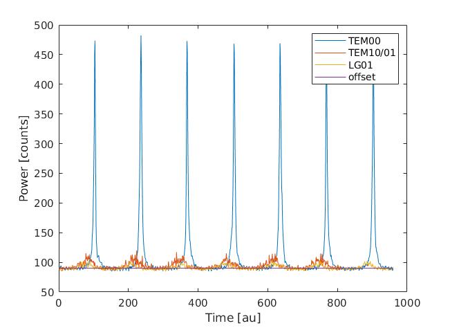
TEM00 was scan with AOM speed 60mHz and deviation 6kHz while TEM01/10 and LG01 were scanned with same speed and deviation 600Hz. Taking into account these factors we can calibrate these signals with calibration = 2*deviation / (1 / (2/speed)) = 2 * 2 *speed * deviation where the first '2' comes from green to IR conversion and second one to get the half-period of AOM scan.
In figure 1 you can see these 3 scans.
The mode-matching was estimated by computing the area under each curve after removing the offset (90 counts).
It gives 4.1% misalignment and 1.3% mode-mismatch and overall value of 5.4%
ROUND-TRIP LOSSES :
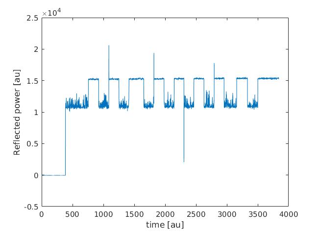
We did as reported in the RTL estimation paper (namely switch on/off resonance of BAB).
We got the results attached in figure 2.
In addition to the mode-matching, we also assumed 8% of RF sidebands power and 1% lost due to laser fluctuations.
It gives round-trip losse of 116 ppm in good agreement with previous estimation.
The mode-mismatch was slightly over estimated as I divided by tem00 power and not total one...
The corrected values are : misalignment = 3.9%, mode-mismatch = 1.2% and total 5.3%.