NAOJ GW Elog Logbook 3.2

In the CC1 PD (TAMA 14MHz resonant PD), LMH6624 is being used (this modification was done in 2019). However, a relative large resistor (1.1kOhm) is being used to connect + of LMH6624 and ground. This connection should introduce lots of thermal noise. Therefore, I would like to replace it with a 10Ohm resistor. Accordingly, the other resistor which is used to amplify signal is changed from 13kOhm to 130Ohm.
Before this resistor replacement, I made several measurements as a benchmark. The green pump power used in this test is always 30mW.
Signal from PD: -51.3dBm. Noise from PD: -83.2dBm (SNR: 31.9dB)
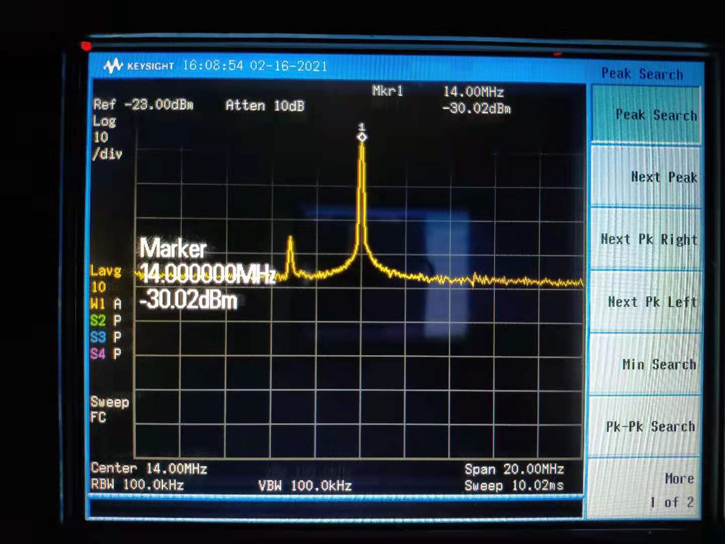
SIgnal after amp: -30.0dBm. Noise after amp: -70.4dBm (SNR: 40.4dB)
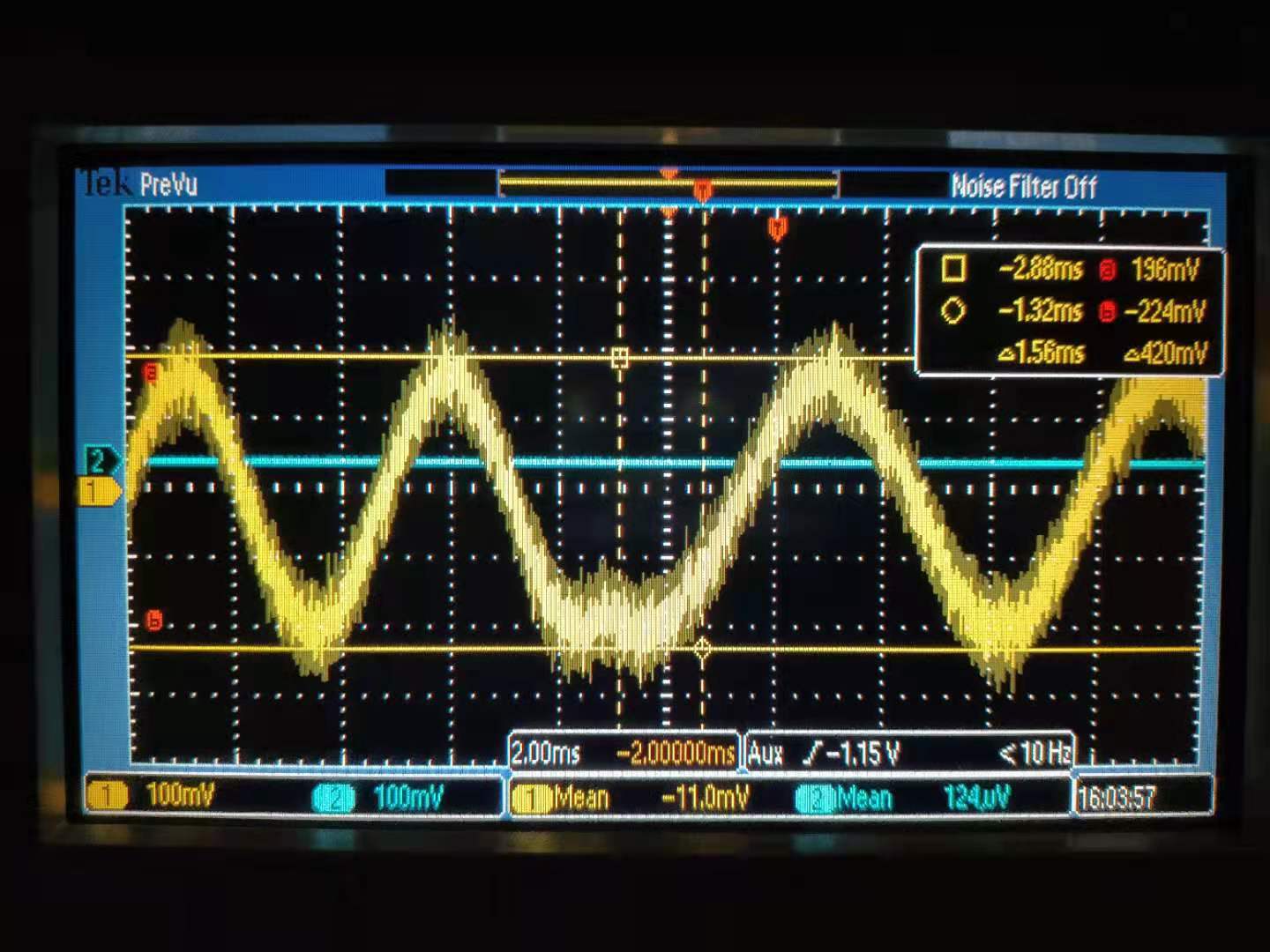
After demodulation, the signal time-series is measured by oscilloscope. Its pk-pk is 420mV. Thickness of singal line is 76mV. (SNR: 5.5)
After resistor replacement, the same measurements were also performed. And I got:
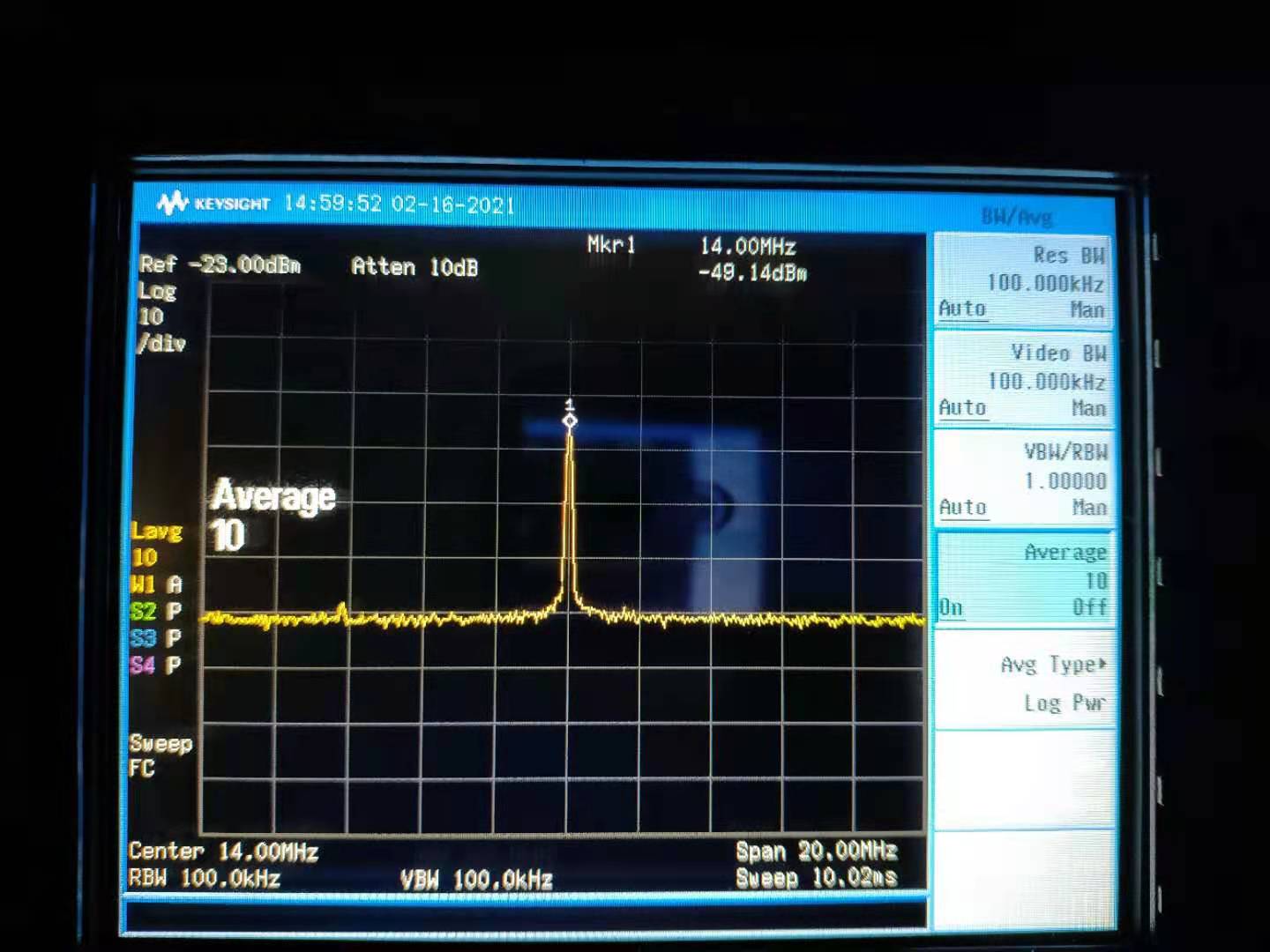
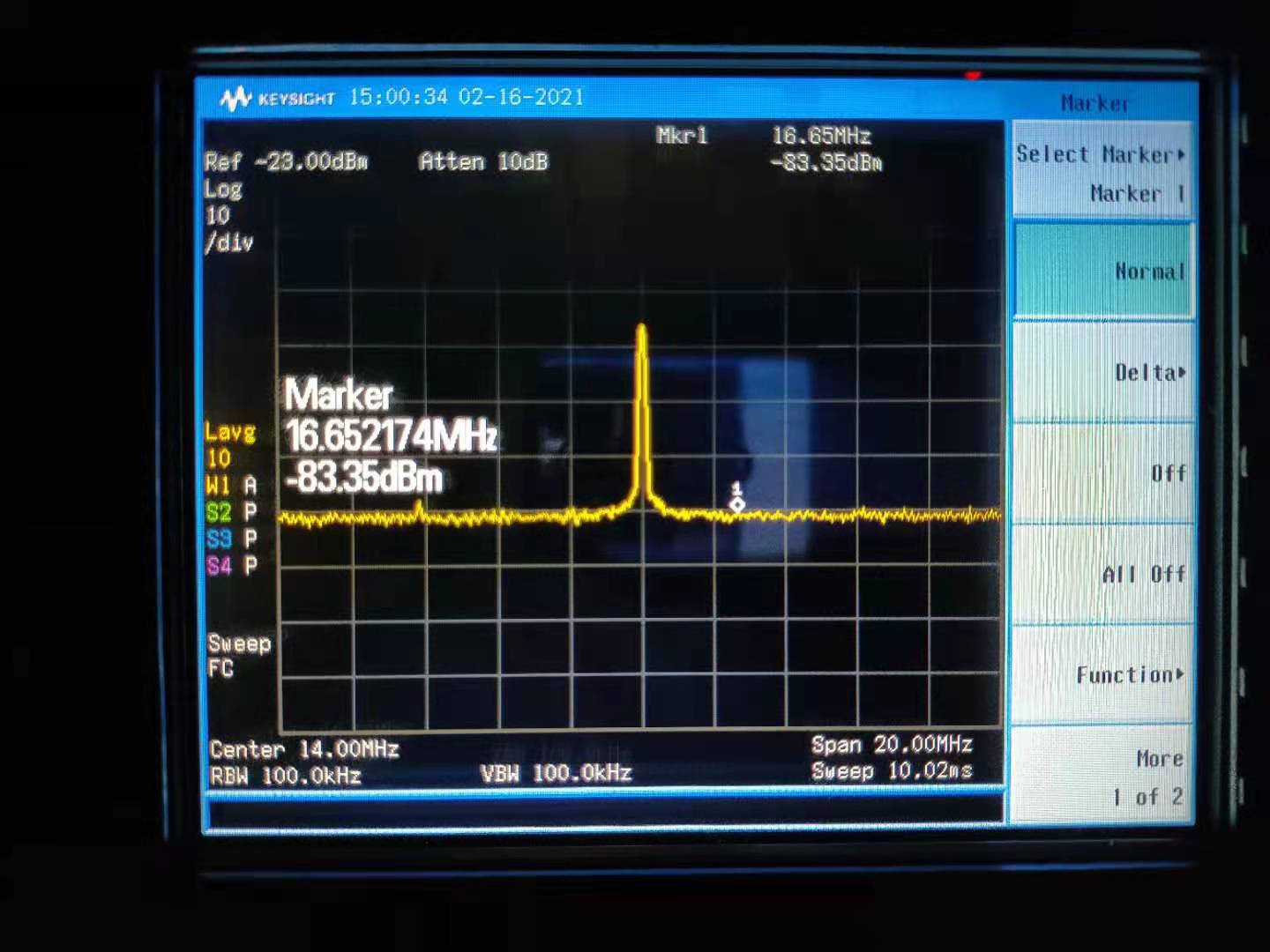
Signal from PD: -49.1dBm. Noise from PD: -83.4dBm (SNR: 34.3dB)
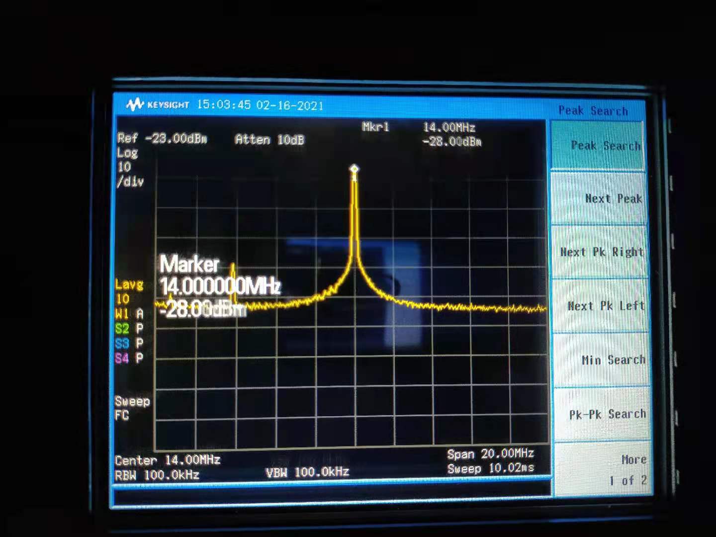
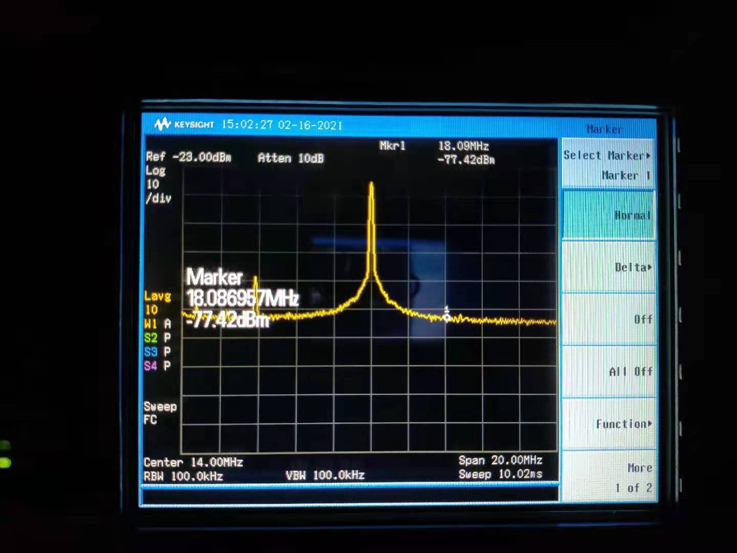
SIgnal after amp: -28.0dBm. Noise after amp: -77.4dBm (SNR: 49.4dB)
After demodulation, the signal time-series is measured by oscilloscope. Its pk-pk is 88mV. Thickness of singal line is 20mV. (SNR: 4.4)
(The demodulated signal is a bit strange. Although the 14MHz peak becomes larger but the demodulated signal is smaller.)
It seems the SNR improvement is obvious by replacing resistor. However this improvement is only visible before demodulation. The demodulated signal (checked from oscilloscope) even becomes worse. For demodulation, we upgraded DDS to provide saturated LO for each demodulator/mixer. But maybe we still have some issues about signal demodulation.
I have already changed resistor back to the original situation. And put CC1 PD back.


Marc, Yuhang
Today we pursued the investigation of this photodiode. Especially, we investigated if there is some offset present that could saturate the mixer used for the demodulation.
First (with high resistors of previous entry) we measured an offset of -1.68V.
Adding a DC block reduces it below 2mV.
Then, we replaced the resistors (low in previous entry) :
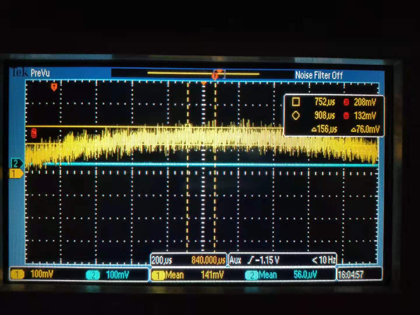
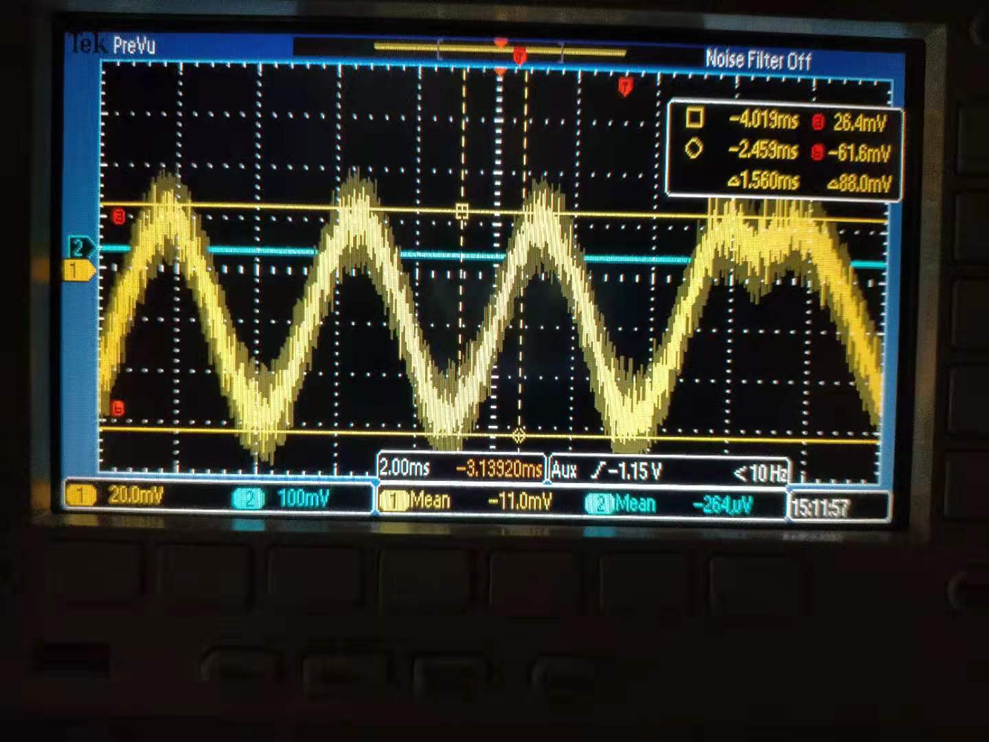
We measured an offset with mean value -90mV and also a clear frequency modulation around 180MHz and peak to peak around 148 mV (Fig 1)
Adding a DC block reduced the offset mean value to -2mV but the signal around 160MHz had an increased peak to peak amplitude around 360mV (Fig 2)
As there is a 20dBm amplification after the mixer, this high frequency signal is larger than the 14MHz one (at -10dBm) and is close to saturation of the mixer.
We'll try to compare this result with simulation (performed up to 100 MHz for now)
360mV pk-pk corresponds to -4dBm, after a 21dB amplifier, it becomes 17dBm (50mW). According to the specification of frequency mixer (ZX05-1L-S+), it may have permanent damage if the RF power is more than 50mW. Therefore, we have been already reaching this threshold due to this 160~180MHz oscillation. This seems to be the reason of demodulation problem when (R1=11Ohm, R2=130 Ohm) are used. A filter to remove this oscillation may help to solve this problem.
We checked again the simulation of this PD up to 200MHz (see attached figure 1). It has voltage noise increase around 120MHz, but this peak is not very sharp. Therefore, we still don't quite understand why we have such large oscillation when (R1=11Ohm, R2=130 Ohm) are used.
We also took some measurement of PD spectrum.
Attached figure 1 shows the measurement of CC1 PD noise after demodulation for different incident power. In this figure, op-amp LMH6624, R1 1.1kOhm, R2 13kOhm are used.
We could see that noise becomes to be shot noise limited when laser power reaches around 300uW. Therefore, I confirmed that electronic noise was still limiting in this case. Then I checked again the simulation, which shows the noise is limited by the resistor. However, according to the simulation, shot noise should start to limit after laser power reaching 3mW.