NAOJ GW Elog Logbook 3.2

The error signal in time tells phase information(error signal in/out of phase with driving) and locking information(if error signal is around zero, the locking is good). Therefore, I checked WFS error signal in time on QPD1/2 while driving/nodriving INPUT/END mirror Pitch/Yaw separately. This time, the driving is at 2Hz.
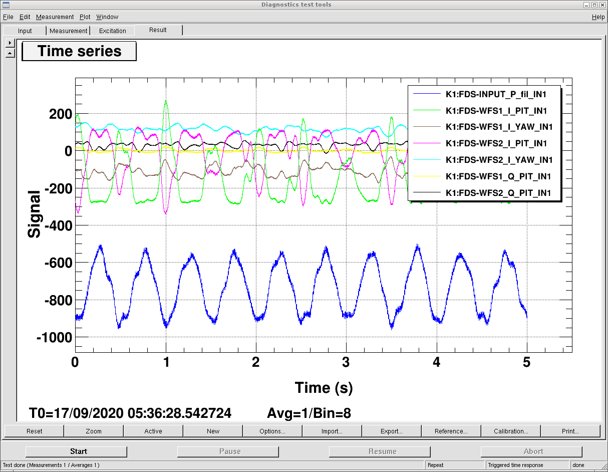
Figure 1: no driving. Even when there is no driving, the pitch error signal oscillates around zero, which indicates mirrors have very large oscillation in pitch direction (known before in other ways).
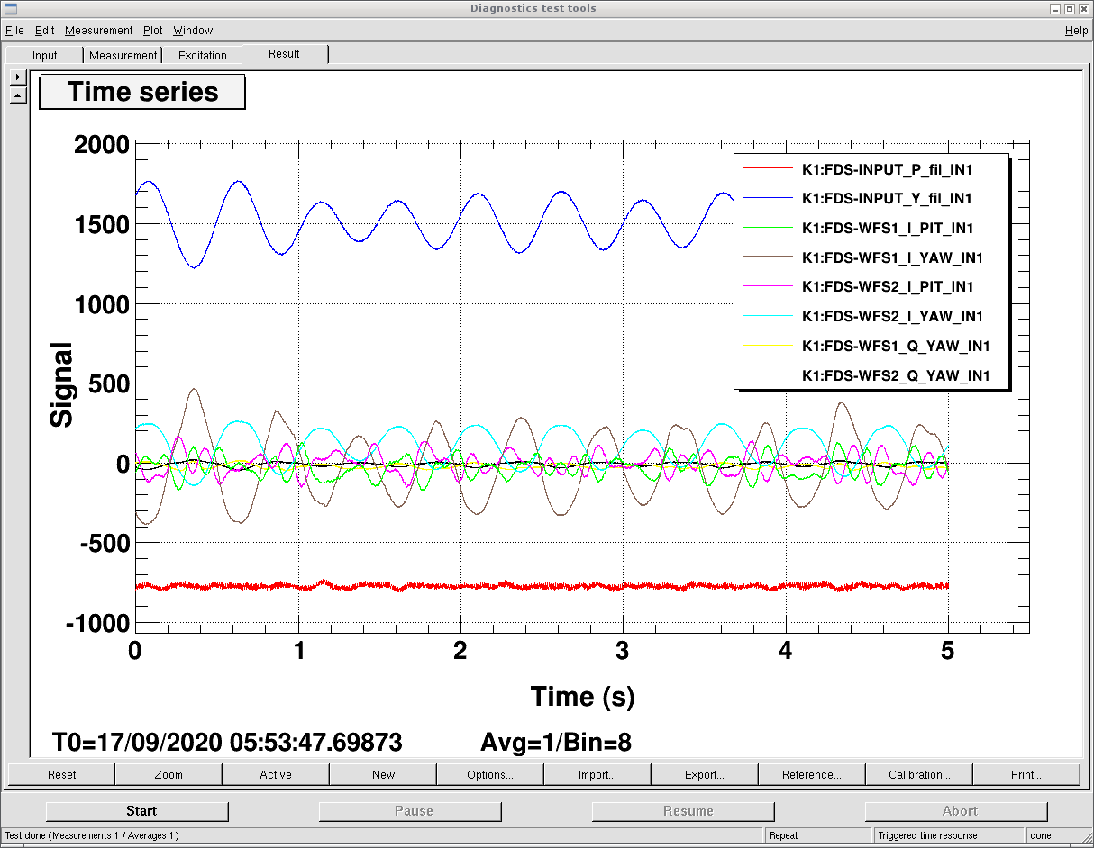
Figure 2: Drive INPUT pitch. We could see WFS1 reconstructed pitch error signal is in phase with the local control pitch motion (driving). But WFS2 reconstructed pitch error signal is out-of phase with the local control pitch motion (driving). We could see that there is some signal in Yaw error signal, but if you compare it with the no driving case, this Yaw error signal fluctuation seems not to be from Pitch driving (or coupling is covered by yaw original fluctuation). (The coupling to Q_phase is also very small)
Figure 3: Drive INPUT yaw. We could see WFS1 reconstructed pitch error signal is out-of phase with the local control yaw motion (driving). But WFS2 reconstructed pitch error signal is in phase with the local control yaw motion (driving). The pitch/yaw is also not visible. The coupling to Q-phase is also quite small.
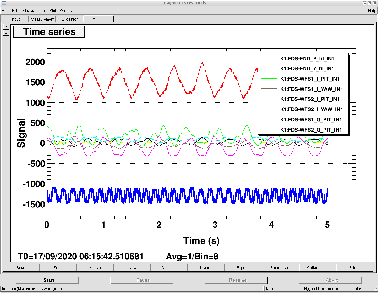
Figure 4: Drive END pitch. Both WFS1/2 are giving out-of phase error singal. The coupling to yaw could be seen in WFS1. There is also lots of coupling to WFS2 Q phase (will not be used to feedback, so it's fine).
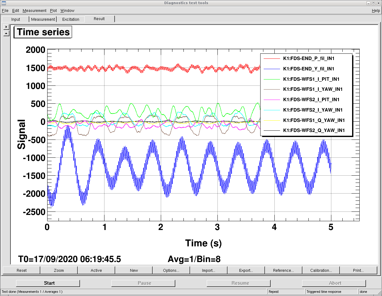
Figure 5: Drive END yaw. Both WFS1/2 are giving in-phase error signal. The coupling to pitch is not obvious. The coupling to Q phase is also not obvious.
The phase information could be used to decide the sign for feeding back.

According to the WFS error signal in time, it can be inferred that situation of QPDs location is shown in the attached figure.
In this case, the error signal from input mirror is shown with opposite sign on QPD1/2. While the error signal from end mirror has the same sign.