NAOJ GW Elog Logbook 3.2

Takahashi-san, Yuhang, Eleonora
With the help of Takahashi-san we assembled the new GR phase shifter by gluing PZT and mirror on the new mount.
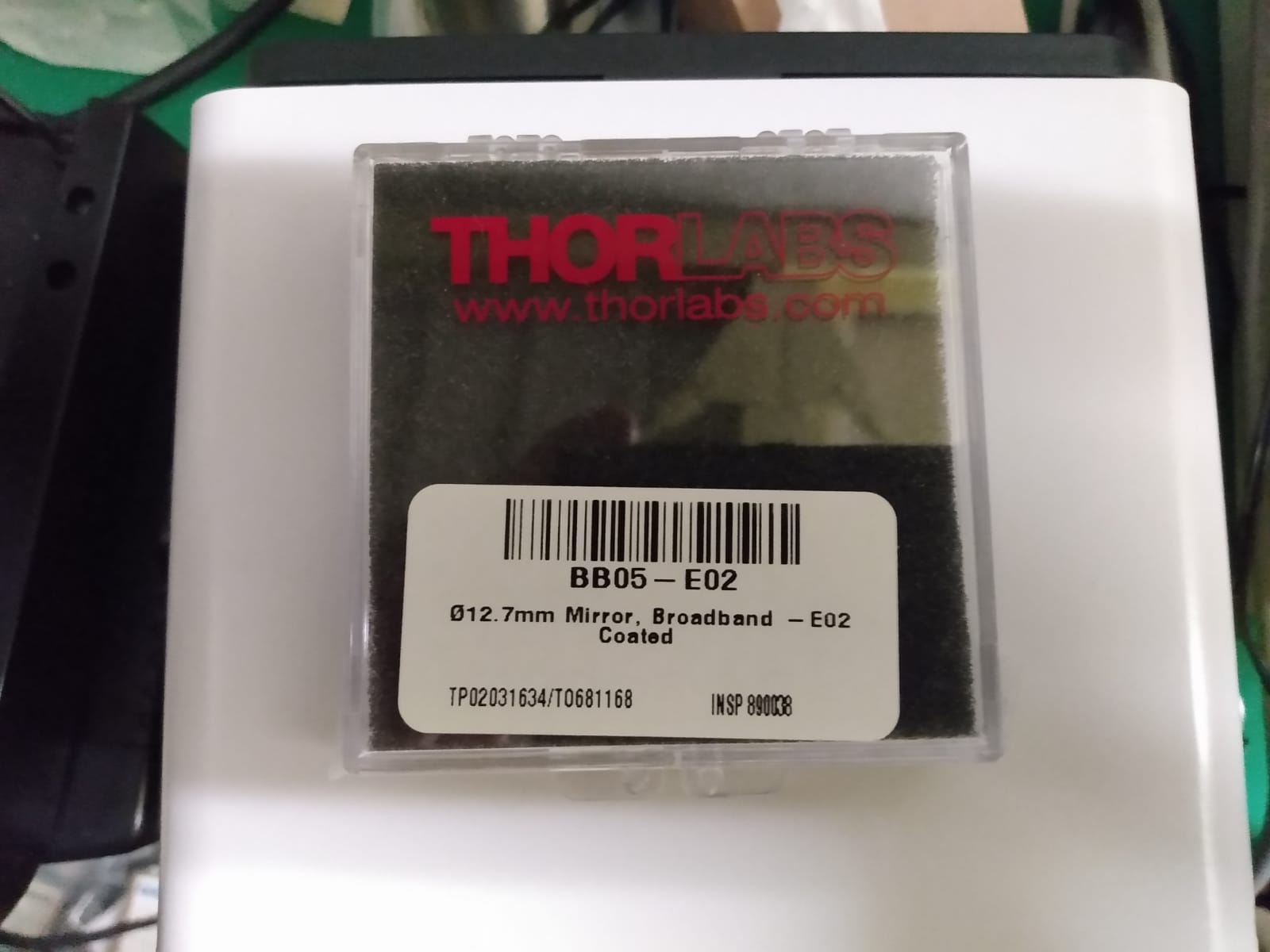
The GR mirror spec are shown in pic 1.
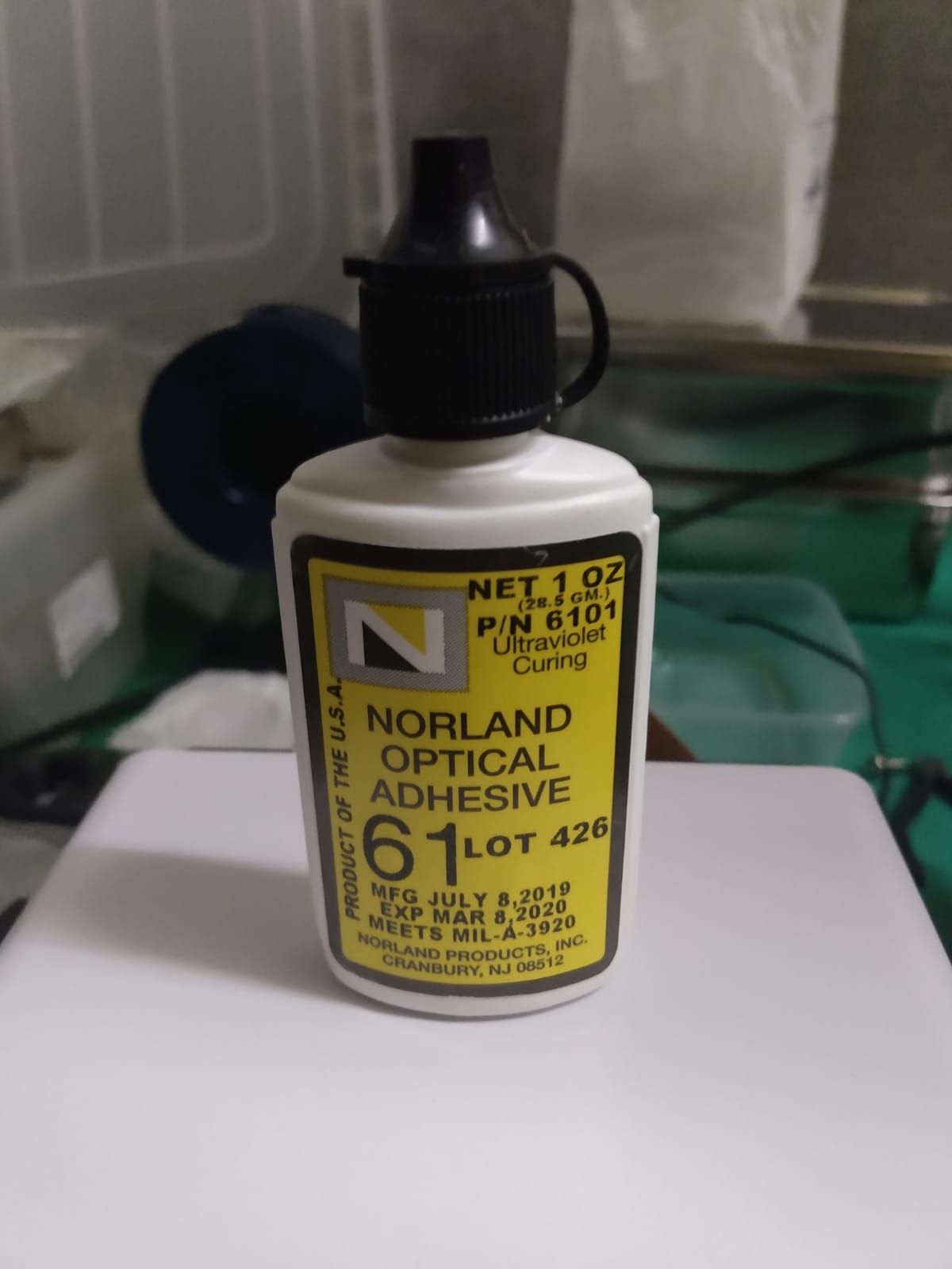
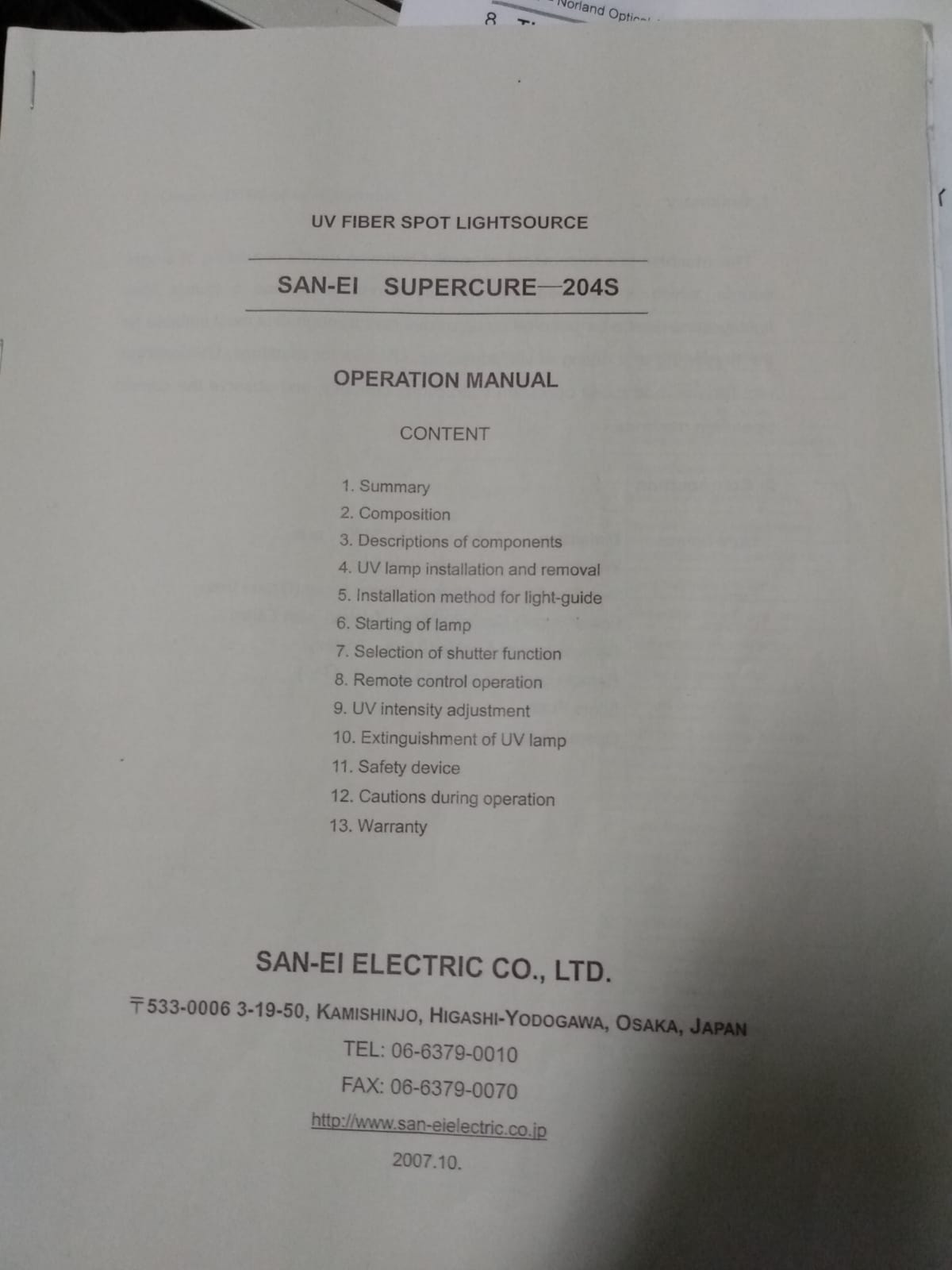
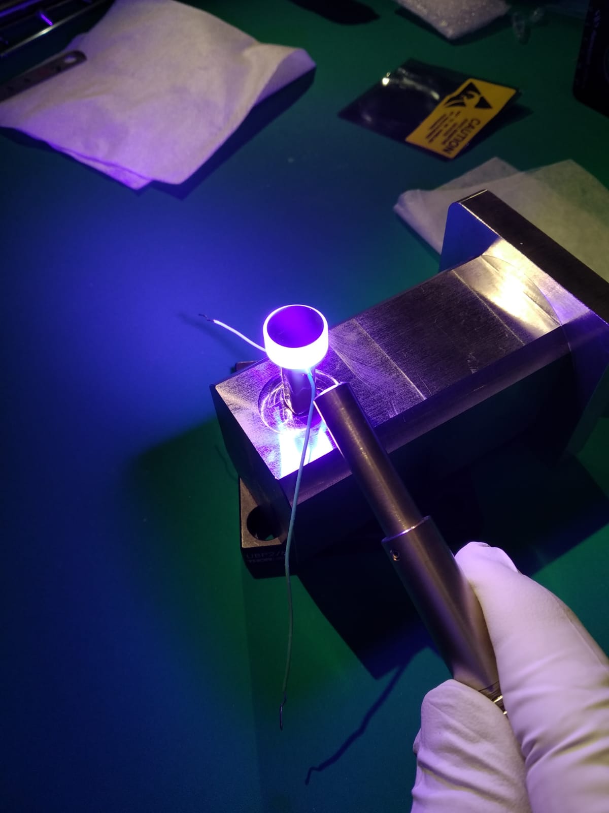
We used a glue (norland optical adhesive 61 in pic 2) that cured by 10 min exporsure to UV lamp (that lamp usually stored in 20 m lab, see manual in pic 3)
We soldered the new pzt connector(pic 5, green wire of PZT is positive) and replace the old phase shifter.
New alignment method for GRMC: since the new phase shifter doesn't have knobs to be adjusted, the alignment of GRMC now relies on the lens and one steering mirror between MZ and GRMC. Just as a memo, Yuhang moved lens position horizontally by hand. Besides, the alignment strongly depends on the voltage applied on pzt, so remember to turn on high voltage driver for green phase shifter before the lock of GRMC.
The CC1 TF (before and after replacment) is shown in pic 8. The phase noise measurement is shown in pic 6. The signal used to calibrate phase noise is shown in pic 7.
After the phase-shifter replacemnet the CC1 loop was much more stable and never got unlocked. There is 10dB attenuation for the error signal injected to the servo and the gain had to be reduced to the minimum.