NAOJ GW Elog Logbook 3.2

[Yuhang, Yuefan, Matteo, Eleonora]
Motivated by the transmission issue reported in entry # 1672 we have investigated the goodness of green beam alignment and matching into FC.
First, we have checked that the beam was centered on both input and end mirror. To do this we have steered the beam with the BS on each side of the mirrors in order to make it more visible since it was hitting the suspension frame. We have recorded the BS position for the beam at the two sides and choose the middle point at a reference position. We confirmed that the beam position was already good even if the precision of this measurement is limited to, let's say, ~5mm. This was done to center the yaw, but it also allowed to assess the pitch centering while the beam was on a side. We could also have done the opposite and steer the beam from top to bottom with BS using the mirror top and bottom frame as reference.
Note that for the end mirror we could reach only the right (back toward input mirror) leg of the suspension, while the beam was hitting the pipe before reaching the left leg. So we used the earthquake stoppers as side references. The camera at the end was aligned to make the beam centered in this configuration. Actually, it was already in a good position.
Then, we scanned the cavity after having aligned it at our best. We kicked the end mirror by applying a large offset to the coils and check with the length oplev the excitation of the pendulum motion.
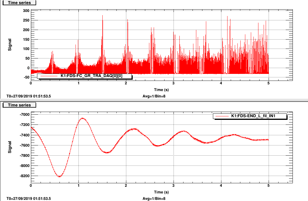
Pic 1 shows the flashes in transmission (top) and the length op lev (bottom). As expected the height of the peaks is smaller and the density is higher when the cavity is moving faster. Note that there seems to be a delay of the oplev signal wrt the transmission one. Actually they arrive from the end room with two different fiber system (old tama fiber system for oplev and new fast optical fiber for transmission)
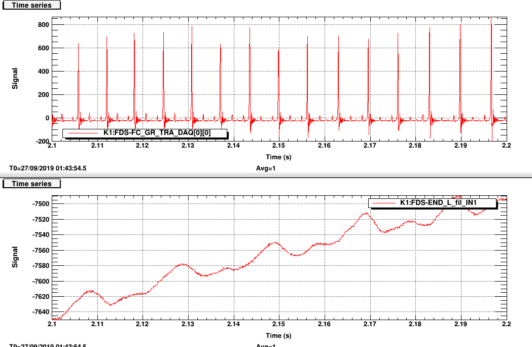
We zoomed in a region when the velocity is constant so that it is easier to identify FSR. (See pic 2). It seems that HOM are reasonably small (the fact the higher peak is TEM 00 is confirmed by the flashed in the camera).
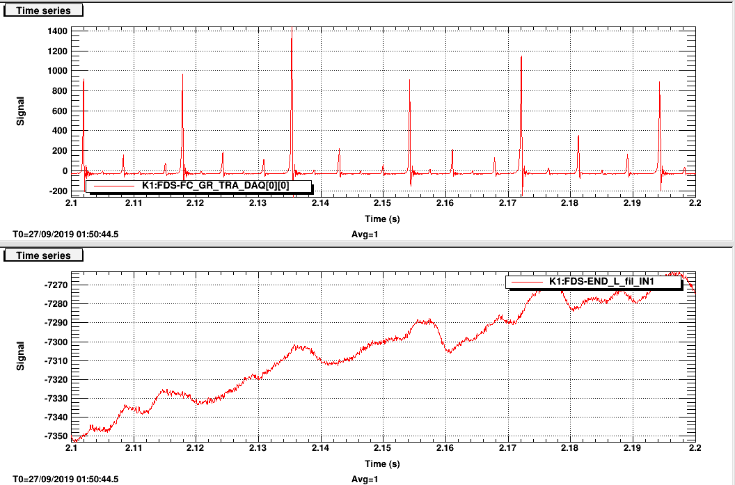
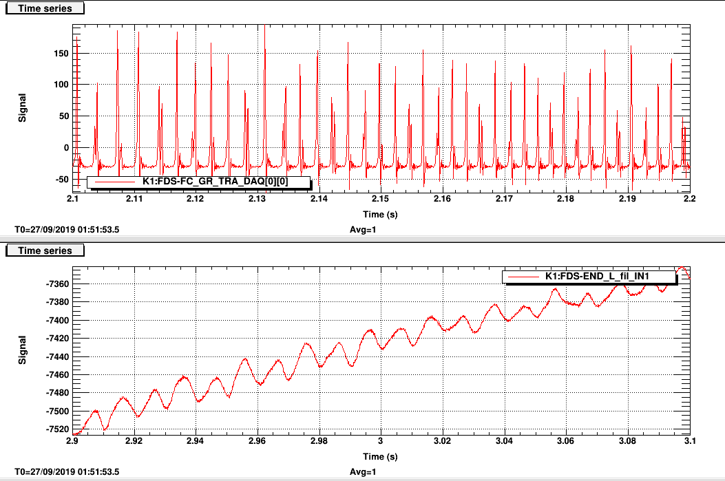
We have misaligned on purpose the pitch and observed that the HOM become higher as expected. (Pic 3-4). I think this measurement confirms that we don't have a major problem with matching and alignment that can justify a drop of the transmitted power to half of the previous power. Anyway a more refined measurement, with the identification of HOM would be nice.