NAOJ GW Elog Logbook 3.2

Participaint: Enomoto, Eleonora and Yuhang
According to the design of telescope, we installed it to match the beam between OPO and GRMC. The method is to use the green light generated by OPO and send it through telescope to GRMC. Then make this green light resonant inside GRMC. In this case, the transmission of GRMC will also resonant inside OPO.
The procedure is like this:
1. Install the telescope in the designed position.
2. Make both OPO and SHG produce green. And then make the transmission of GRMC overlap with the green produced by OPO.
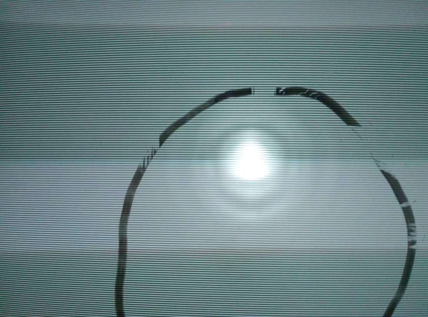
3. Swith off SHG. Put a camera in the transmission of GRMC to monitor the transmission signal. See attached photo 1. At that time, the mode matching is very bad. See here, the scan of GRMC shows also the mode-mismatch situation.https://drive.google.com/open?id=1QDXRWudVucsCfB4_BUoiSu5zzuikkT8l
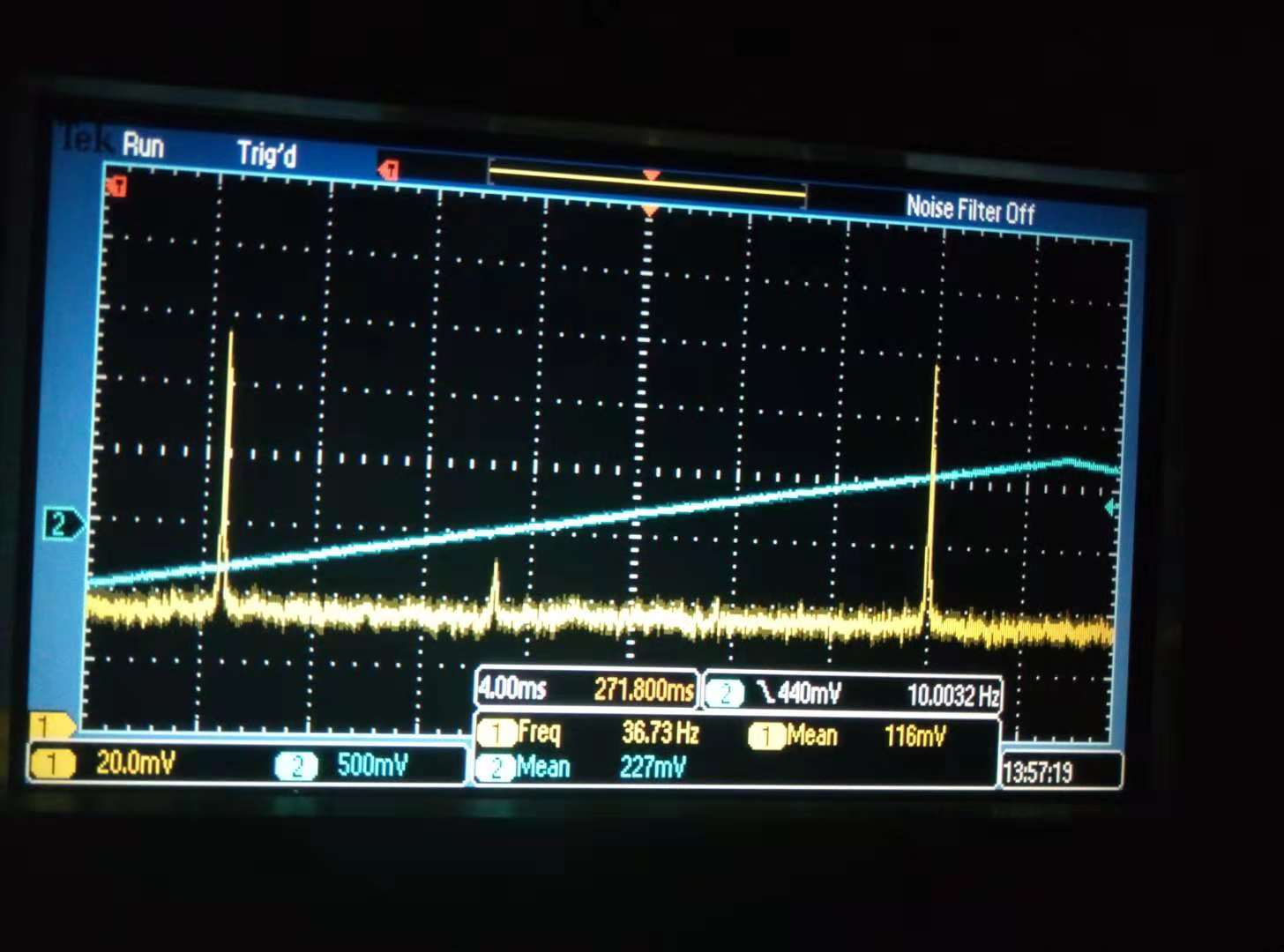
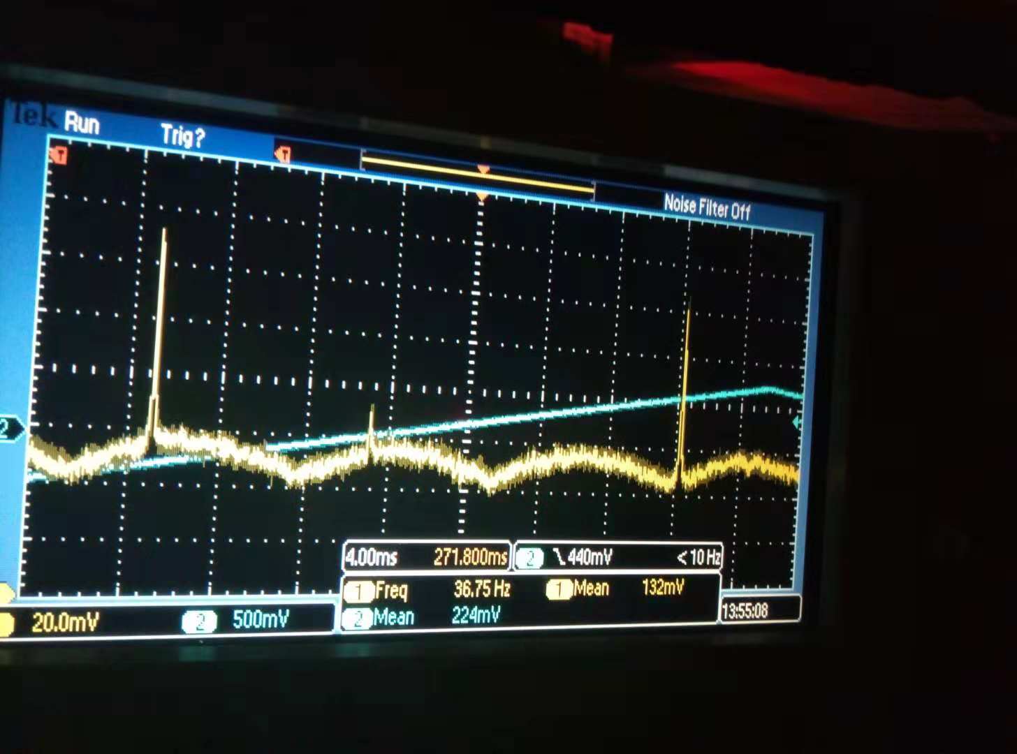
4. Do rough mode matching improvement by looking at the camera, and then make the pattern on the camera has less Laguerre-Gaussian mode. After this, we have on camera this. https://drive.google.com/open?id=1C7Pt_8Wltid6sxGtgC08nJ0exEal21ln Now we can see the beam by eye, then center it on PD. We can see the GRMC transmission while scanning the GRMC. At the same time, we tried to close the light. By comparing the signal on oscilloscope of attached figure 2 and 3, we found the ambient light just increase the offset but not cover the real signal.
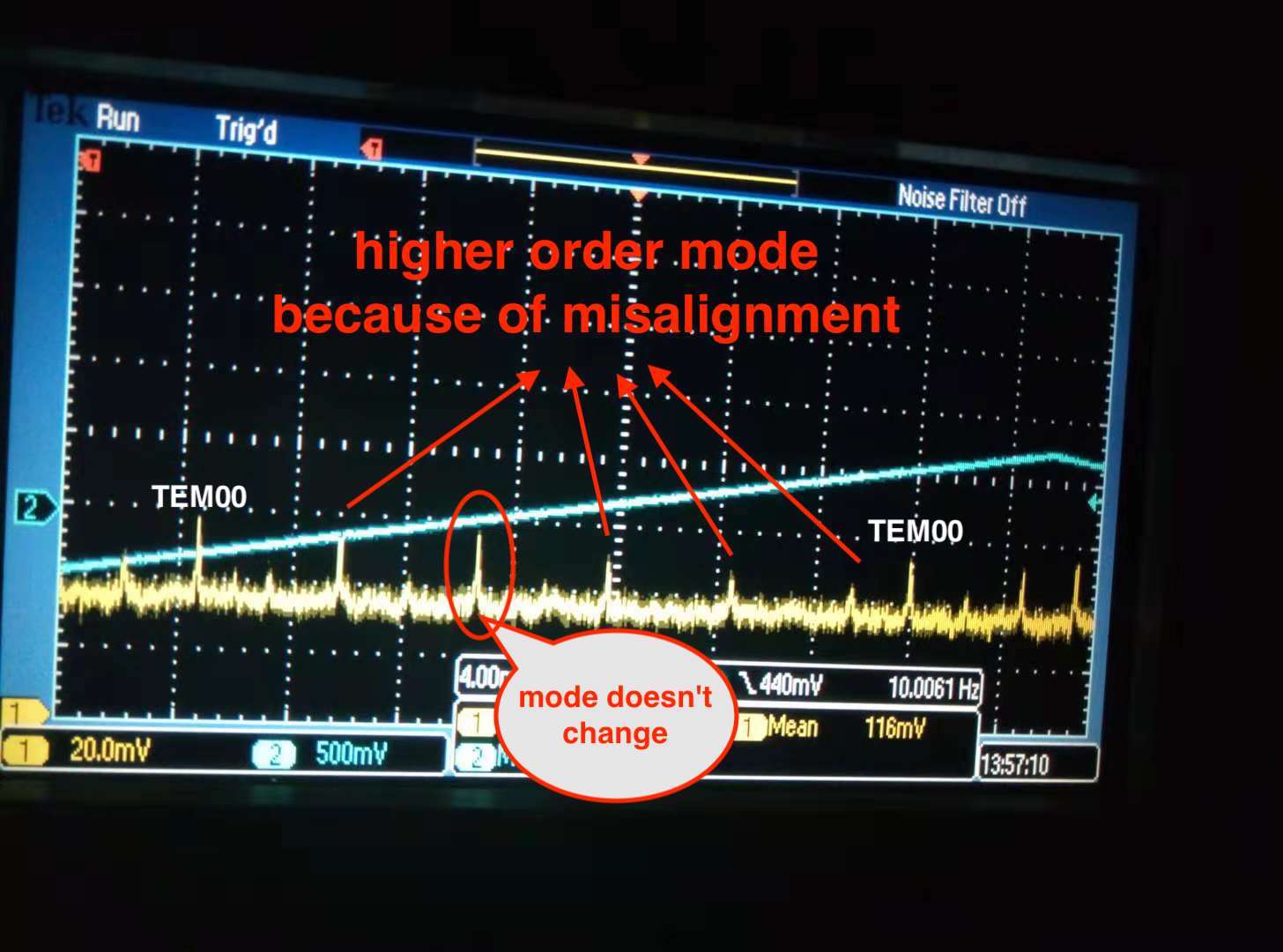
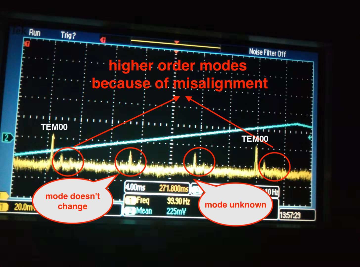
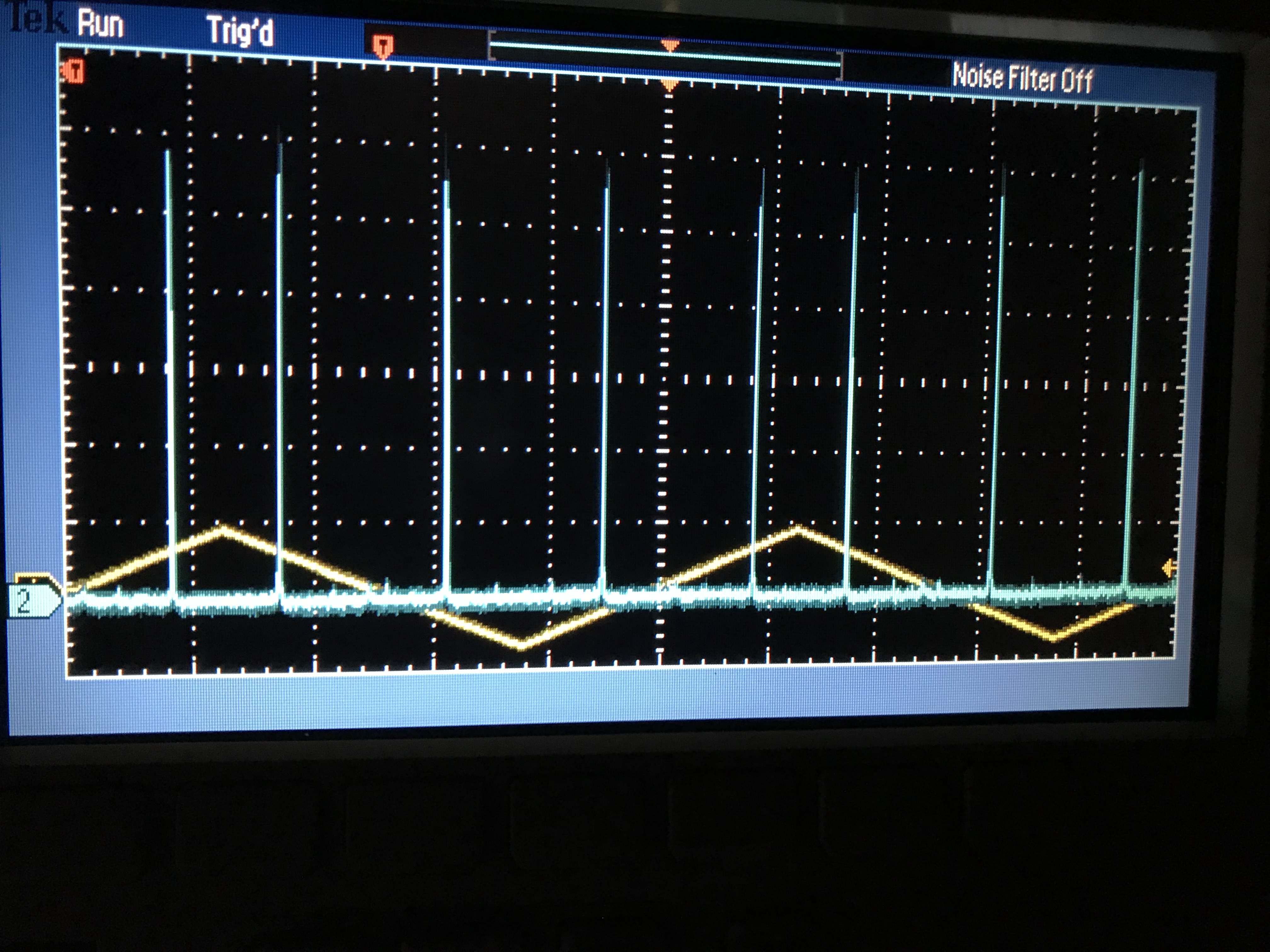
5. Now we can improve mode matching and alignment again. We misalign pitch and yaw to identify the higher order modes(See attached figure 4 and 5). As you can see in the attached figure, the peak we have in the best case doesn't change no matter how we misalign the beam. So we decide to remove that peak by improving the mode matching. However, we also found the higher order modes increase only a little bit although TEM00 is reduced. This is just evaluated by summing up the height of the higher order modes and reduced TEM00, then compare this sum with the previous TEM00 height. We found the case of misalignment is smaller than the good case. This maybe mean that we loss some energy to soemwhere else. And we cannot see most of other higher order modes. We guess they are covered by PD noise.
6. But anyway, the information we have now on the GRMC scan can only help us to remove the mode matching peak. We did that and the result is shown in attached figure 6. The video is here.https://drive.google.com/open?id=17Uko8FaUJYfKaxx3gB6HdcTGxy4EefRI If you look at this video, you will see there are still a lot of higher modes. However, these higher order modes don't appear on the scan signal of GRMC. This also means the PD's noise cover these modes?