[ Yuhang, Matteo, Eleonora]
After locking the Green mode cleaner we measured a trasmissivity below 50% which is much lower than what we expected.
An extremely rough power budget gave us:
P_in = 22 mW
P_tra = 8.5 mW
P_ref = 10.5 mW
P_tra from end mirror = 0.5 mW
Missing = 2.5 mW
We investigated some of the following possibilities:
Mirrors transmissitvity
For a triangular cavity, as our modecleaner, the transmission is given by:
T = (t_in*t_out)/1-r_in *r_out *r_end)^2
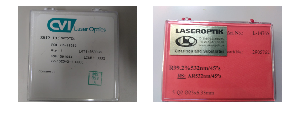
according to the spec for the mirrors used (see pic 1) :
R_in = R_out = 0.992 and R_end > 0.995 (measured from the producer 0.9993)
= > T = 0.92 (taking R_end 0.9993)
Considering an error of +/- 0.003 in all the three nominal transimissivity, the expected cavity trasmissivity is 0.92 +/- 0.33
Matching and alignment
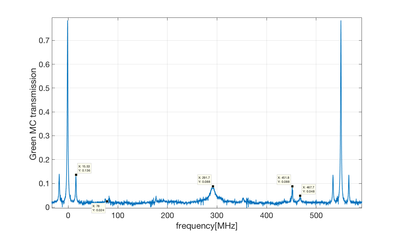
The optical spectrum of the cavity is shown in pic.1. The alignement seems good. The sidebandes at 78 MHz ( used for the lock of the MC) are not visible while we can see the 15.2 MHz modulation that we know to be high.
[ Note that we are sending at the 78 MHz resonant EOM, a driving RF signal with amplitude 1 V pp which should correspond to a modulation depth of 0.185 rad. this means that the expected power in the sidebads is 0.0086]
input beam polarization
Yuhang used a PBS for 532nm and verified that the light is almost all in s-pol, as it should be.
Conclusions: The origin of the low MC transmissivity is not clear but the most probable hypotesis, among those considered, is that the effective transmission of the mirrors are a bit different from the nominal ones.
On the other hand there is a strange "large" peak in the middle of the FSR. Where is that coming from? Is there a polarization problem? In the entry it is written that the polarization is OK.
Question: did somebody already check that the input and output mirrors are mounted with the HR side facing the inside of the cavity?
I checked the input and output mirror. From the point view of marker on the side of mirror, I am sure the mirror is installed in a correct way.
I checked also the mirror from the same box, this arrow points to the HF side of this mirror.
Are the values given above now confirmed?
P_in = 22 mW
P_tra = 8.5 mW
P_ref = 10.5 mW
P_tra from end mirror = 0.5 mW
Missing = 2.5 mW
Are the 2.5 mW still missing?