Participaint: Emil and Yuhang
After change the new servo and new infrared demodulation board, we did a rough phase adjustment. We decided to make it as best as possible, so we changed the green and infrared demodulation phase.
For infrared phase, we change the demodulation phase and find a really small error signal. Then we add 90 degree to get a good phase. However, we cannot get a clear green error signal and we cannot see the difference when we change the phase. For the green locking, we did like this:
1. We lock green.
2. Change the phase until we can see the oscillation of error signal.
3. Decrease the gain till oscillation disappears
Because the gain of SR560 is 1 now, so we connect the demodulation signal directly to Rampotu servo. Now the gain is 4.5 on the Rampeauto board.
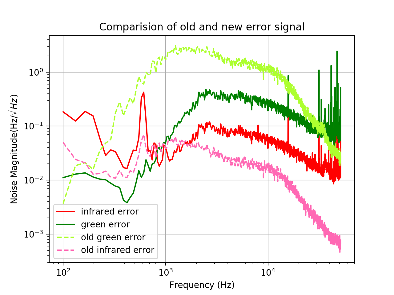
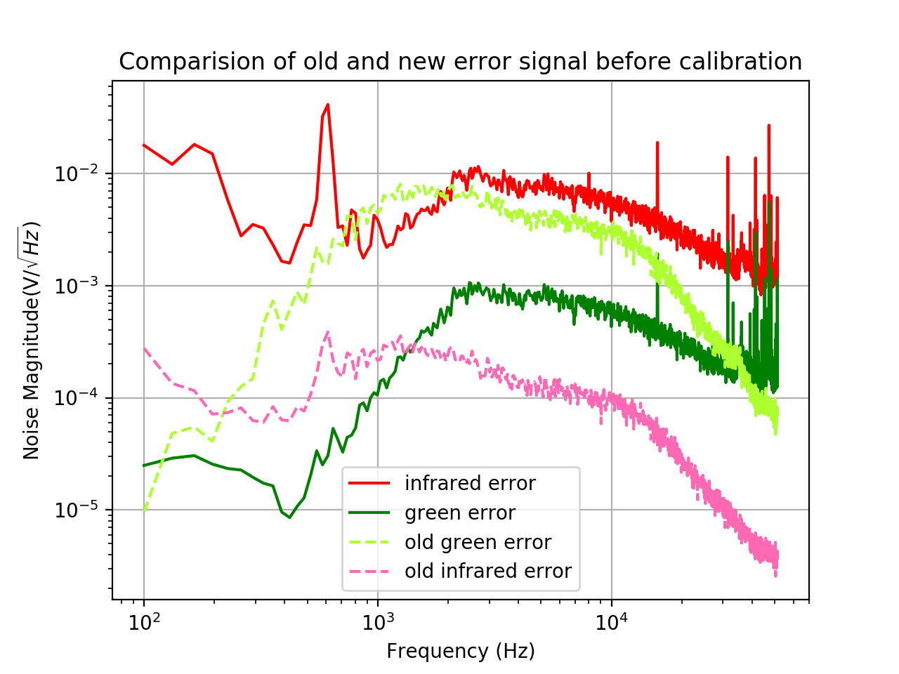
After change the demodulation phase, we measured open loop transfer function and error signal again. I put the result here.
(Note: this time I also attach the error signal before calibration)
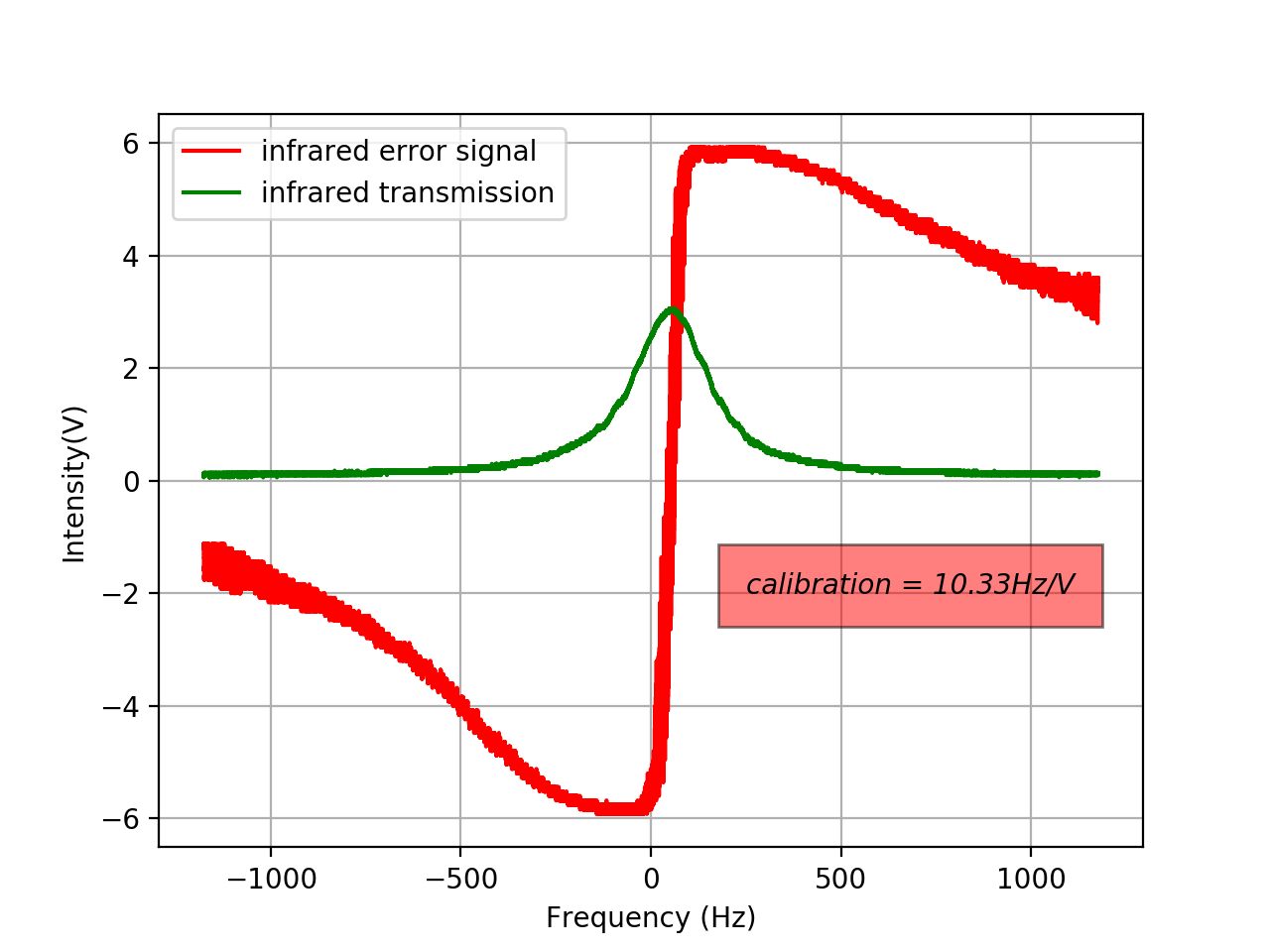
It seems like the peak of infrared error saturates on oscilloscope from picture 3. Maybe we can put an attenuator for it?