YuhangZhao - 00:32, Tuesday 27 February 2018 (680)
The installment of camera(for IR reflection) and the attempt to acquire IR error signal
Participant: Yuefan, Yuhang, Eleonora
1. The installment of camera for IR reflection
Since we have received the filter to attenuate green beam, we tried to install the camera for IR reflection today. Since the power of IR is pretty high, we also used an OD filter(factor of 2) and a partly-reflected mirror to reduce the power. During the adjustment, we can see on the screen that there are two points. The small one is on the right and below side of the large one. Then we tried to change the angle of that partly-reflected mirror and accordingly the camera. At a certain point, we could make it a round point. We believed that that was a good angle.
Then we locked the cavity, this reflection of one point changes to two points.(See attached video 1) We thought that we were looking at the TEM10 mode. However, it should be the superposition of TEM00 and TEM01. According to our knowledge, this reflection can tell us the information of alignment. That means if it is the right reflection, we can use it to refine the cavity. Since we have already been around the best position, so we move the Input mirror around this position to check. What we could see is only these two points changed brighter and weaker one after another.(See attached video 2) Even when we tried to misalign the pitch of End mirror, we couldn't see the TEM01 mode on the screen.(See attached video 3)
Video Note: the interesting part of video are all around the end of video. You can find them by using the date 20180226. You can check them through this link. https://drive.google.com/drive/folders/1v7oSk0d6ONPN-NZTNcYjIuG0ip8XCZOn?usp=sharing
After checking all the things listed above, I felt gradually that it is not the right reflection. But we cannot figure out why we can see it. We need an expert and tomorrow Raffaele will come^_^
2. Attempt to acquire IR error signal
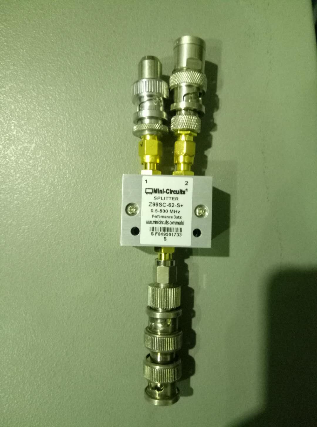
Due to the FWHM of IR is much more narrow than GREEN. The locking accuracy of IR needs to be evaluated by having the error signal directly. Owe to the EOM modulation for SHG, we have the modulation for infrared luckily. So we separate the output of its signal generator by using SMC-type connector(to avoid signal reflection see attached picture 1). We use the reflection from the cavity as RF signal.
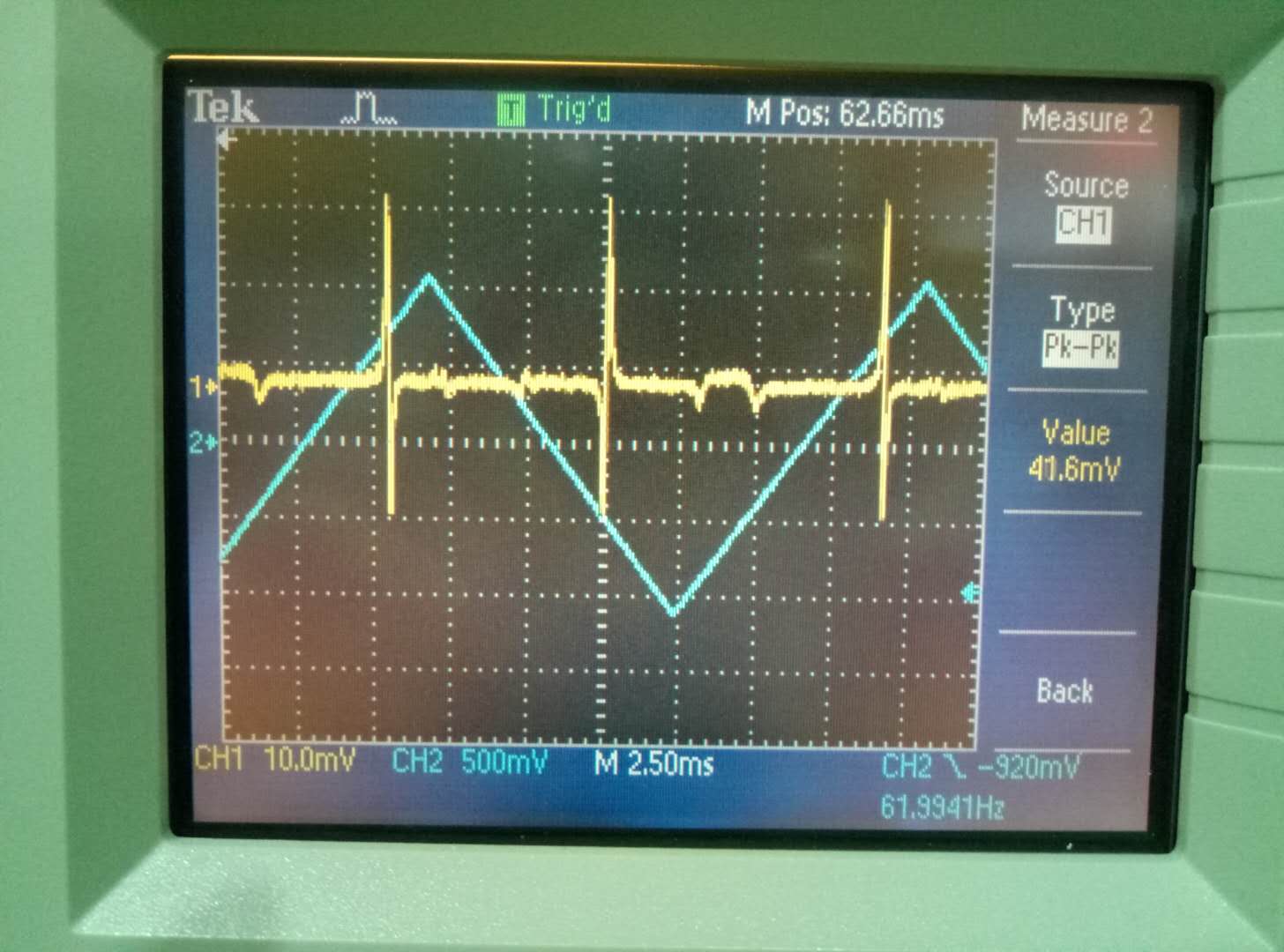
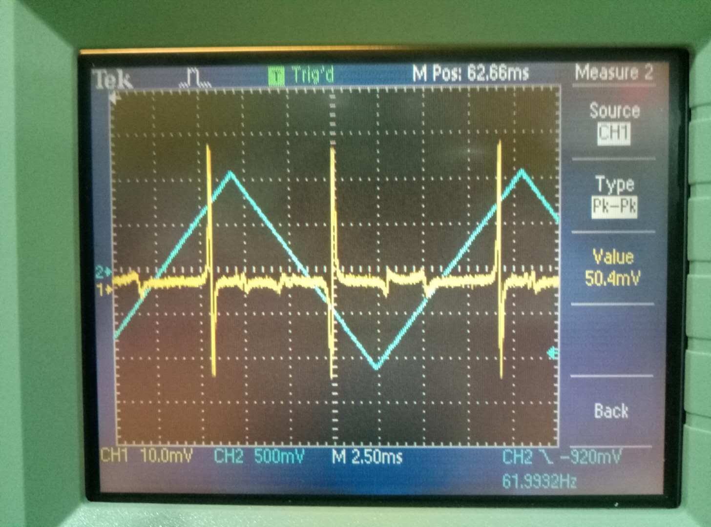
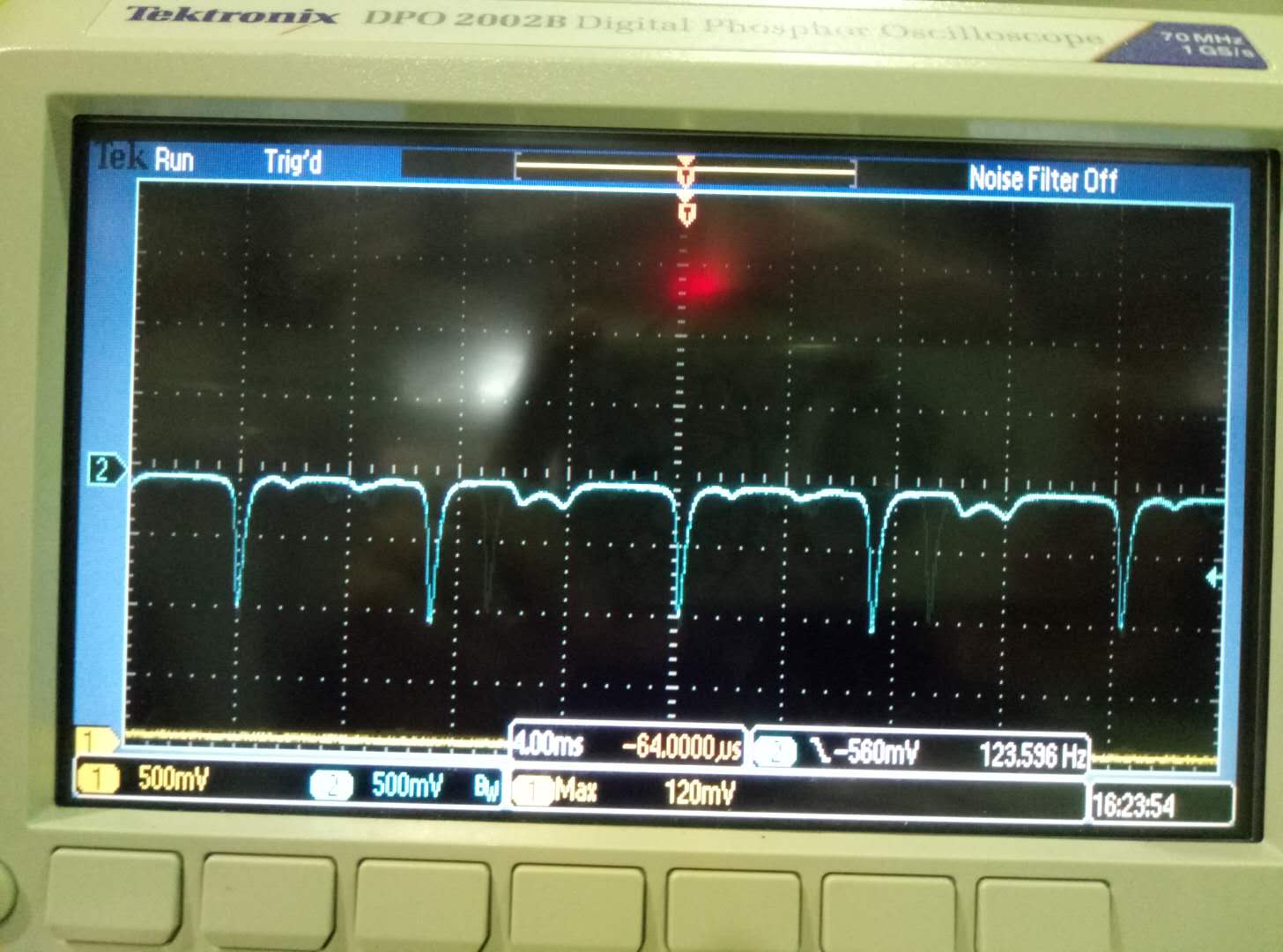
After separation, we succeeded in recovering the error signal for the SHG. By the way, we made this error signal pk-pk value larger than before.(See attached picture 2 and 3) Also we took the picture of different modes we got for SHG.(See attached picture 4)
For infrared error signal, we make the AOM modulate. That means the AOM driving frequency change around the best point with a certain frequency(It's like the ramp signal while we looking for the error signal). But we cannot find the error signal for IR.
For the fail of IR error signal, we found the bandwidth of IR reflection PD is not high enough. Now it is PDA36A(350-1100nm, 10MHz BW, 13mm**2), but our modulation is 15MHz. Certainly we cannot demodulate it. Besides, we also need to check if the demodulation board can work well tomorrow.
1. The installment of camera for IR reflection
Since we have received the filter to attenuate green beam, we tried to install the camera for IR reflection today. Since the power of IR is pretty high, we also used an OD filter(factor of 2) and a partly-reflected mirror to reduce the power. During the adjustment, we can see on the screen that there are two points. The small one is on the right and below side of the large one. Then we tried to change the angle of that partly-reflected mirror and accordingly the camera. At a certain point, we could make it a round point. We believed that that was a good angle.
Then we locked the cavity, this reflection of one point changes to two points.(See attached video 1) We thought that we were looking at the TEM10 mode. However, it should be the superposition of TEM00 and TEM01. According to our knowledge, this reflection can tell us the information of alignment. That means if it is the right reflection, we can use it to refine the cavity. Since we have already been around the best position, so we move the Input mirror around this position to check. What we could see is only these two points changed brighter and weaker one after another.(See attached video 2) Even when we tried to misalign the pitch of End mirror, we couldn't see the TEM01 mode on the screen.(See attached video 3)
Video Note: the interesting part of video are all around the end of video. You can find them by using the date 20180226. You can check them through this link. https://drive.google.com/drive/folders/1v7oSk0d6ONPN-NZTNcYjIuG0ip8XCZOn?usp=sharing
After checking all the things listed above, I felt gradually that it is not the right reflection. But we cannot figure out why we can see it. We need an expert and tomorrow Raffaele will come^_^
2. Attempt to acquire IR error signal
Due to the FWHM of IR is much more narrow than GREEN. The locking accuracy of IR needs to be evaluated by having the error signal directly. Owe to the EOM modulation for SHG, we have the modulation for infrared luckily. So we separate the output of its signal generator by using SMC-type connector(to avoid signal reflection see attached picture 1). We use the reflection from the cavity as RF signal.
After separation, we succeeded in recovering the error signal for the SHG. By the way, we made this error signal pk-pk value larger than before.(See attached picture 2 and 3) Also we took the picture of different modes we got for SHG.(See attached picture 4)
For infrared error signal, we make the AOM modulate. That means the AOM driving frequency change around the best point with a certain frequency(It's like the ramp signal while we looking for the error signal). But we cannot find the error signal for IR.
For the fail of IR error signal, we found the bandwidth of IR reflection PD is not high enough. Now it is PDA36A(350-1100nm, 10MHz BW, 13mm**2), but our modulation is 15MHz. Certainly we cannot demodulate it. Besides, we also need to check if the demodulation board can work well tomorrow.
Images attached to this report