Members: Matteo L., Yu-hang Wu
On monday 6th of November several measurements has been performed. Here a list of the measurements and the results with some discussion.
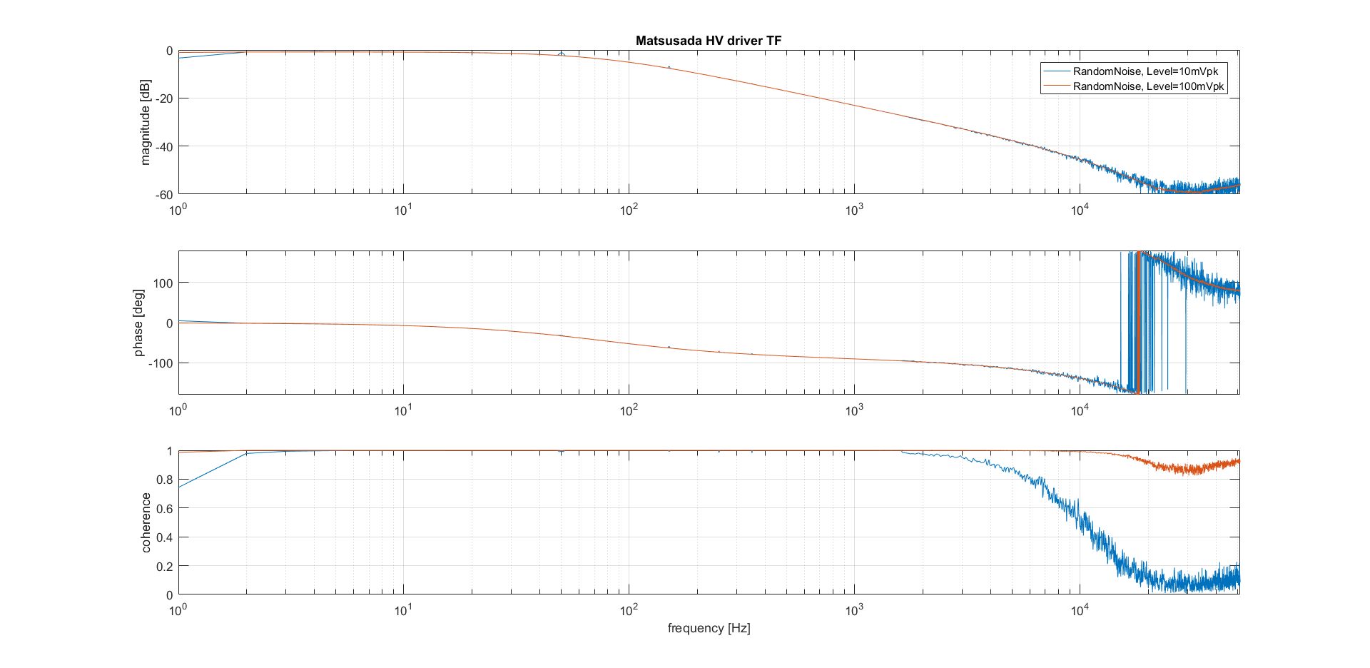
HV driver TF as function of the noise amplitude:
To understand if the low pass filter present in the HV driver transfer function (logentry 582) comes from a bad slew rate of the HV internal op amp, few measurements of the TF as function of the noise amplitude has been performed. The result is presented in Fig.1. If we compare the two measurement presented with the one done previously we see that the pole of the LP filter is unchanged with respect of the noise amplitude and it is always at 77Hz. Therefore the bad slew rate of the op amp does not seem the source of the low pass filter.
High pass filter and HPfilter+HVdriver characterization:
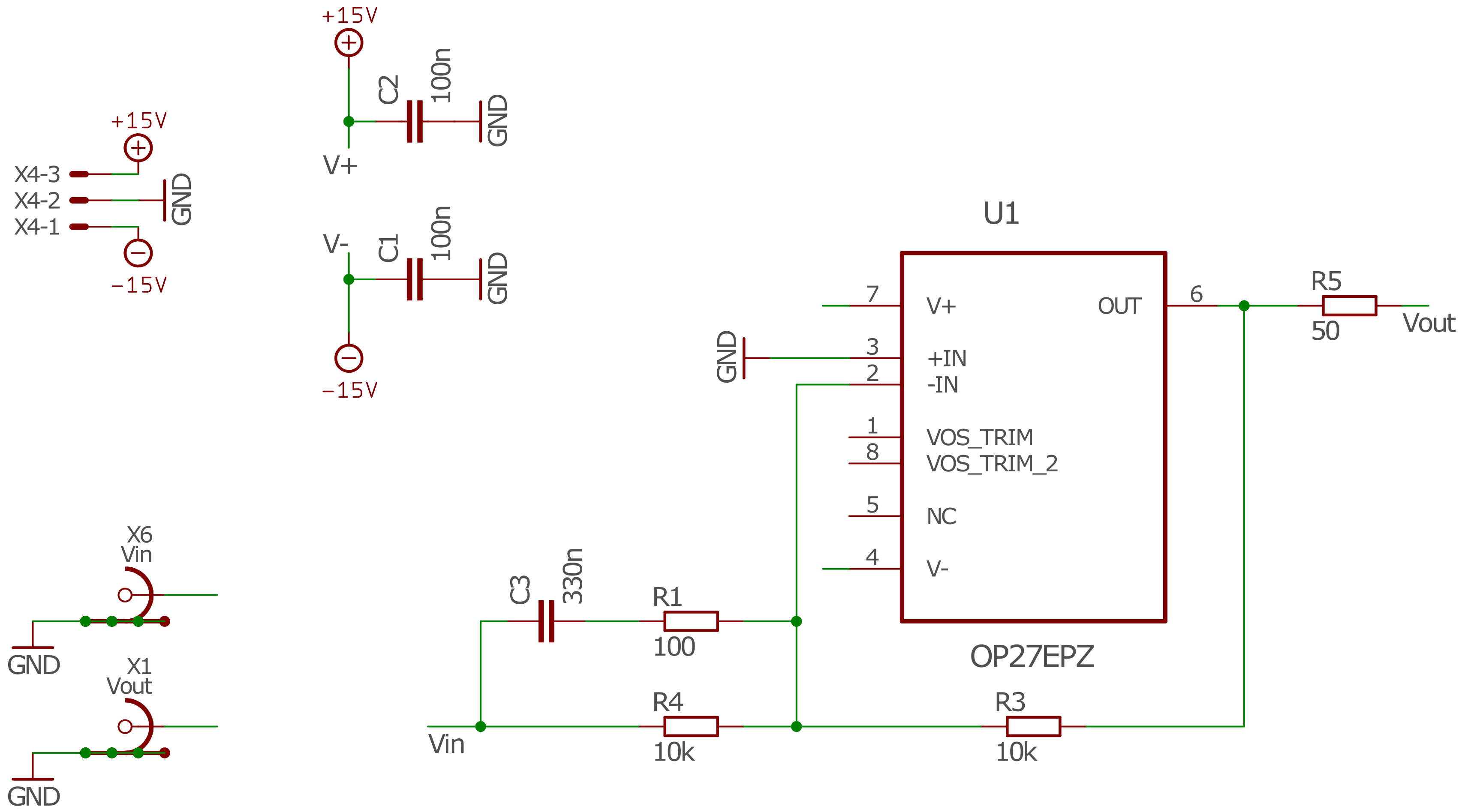
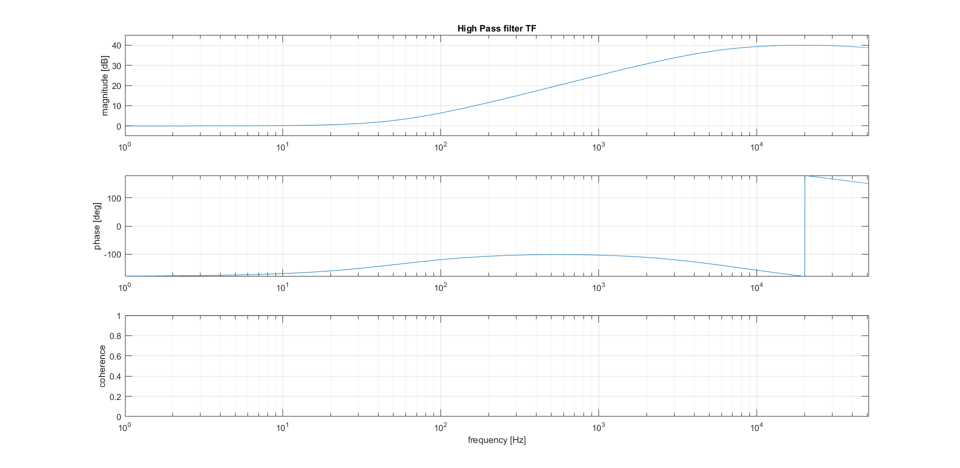
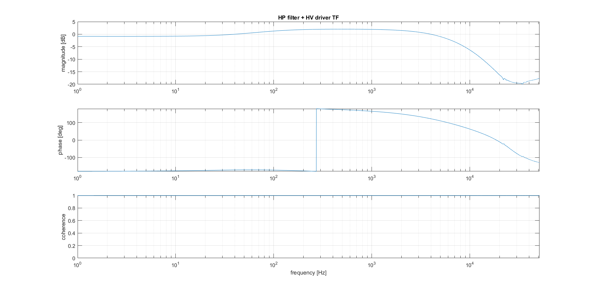
To try to remove the pole in the HV transfer function we added an active, first order high pass filter at the input of the HV driver. The schematic of the HP filter is presented in Fig.2 and Fig.3 shows its characterization. After inserting the HP filter at the input of the HV driver the transfer function of the system has been measured again and it's presented in Fig.4.
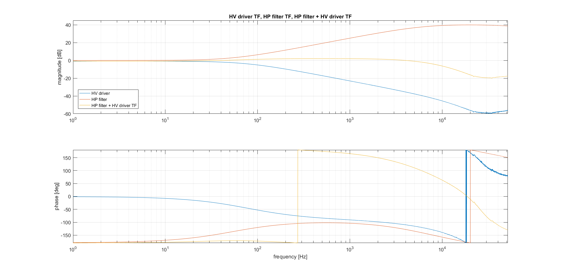
Fig.5 shows a recap of the HVdriver TF before and after adding the HPfilter.
SHG characterization after the modification of the HVdriver:
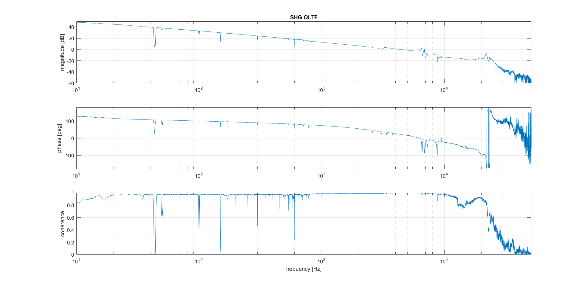
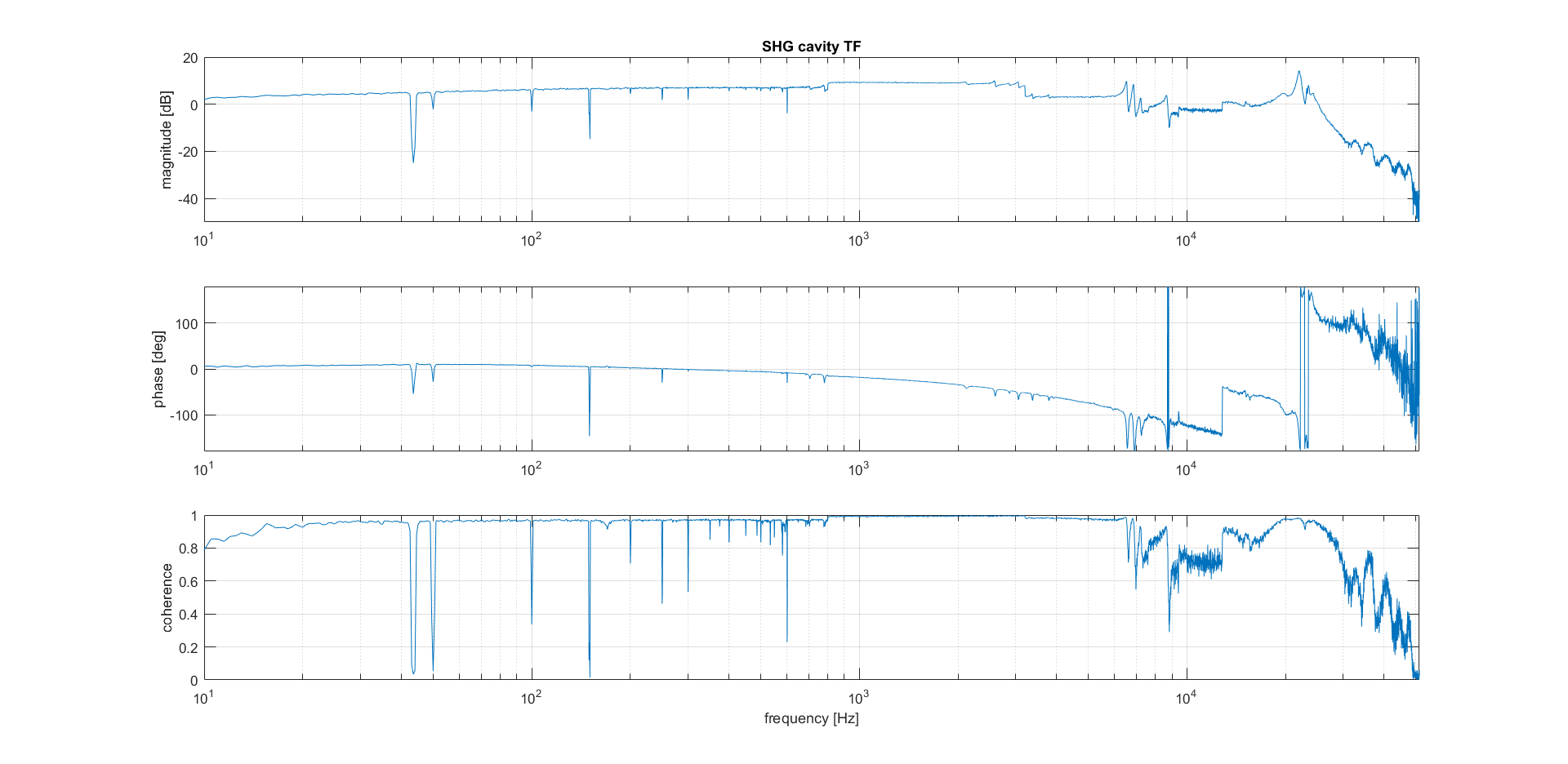
After adding the HPfilter the SHG's open loop and cavity TFs has been measured (Fig.6 and Fig.7). In order to have a stable loop the parameters of the servo (SR560) were changed: Gain=200 (before =1000), f3dB=10Hz (unchanged), invert=ON (before =OFF). Inverting the error signal was necessary due to the 180deg phase delay introduced at low freq by the HPfilter (the op amp is in inverting configuration).
All the TFs presented are pieced together from traces with different frequencies span. Only in the SHG cavity TF (Fig.7) there seems to be some problems going from one span to the subsequent. I don't think this issue is cause by any physical effect but further investigation will be performed.
As a result of adding the HPfilter to the loop chain the SHG cavity TF is reasonably flat below the PZT resonance and the unitary gain frequency of the loop has been increased from approx. 1kHz to approx.4.5kHz. In the next days we plan to play with the servo parameters to improve the unitary gain freq. and the loop stability.
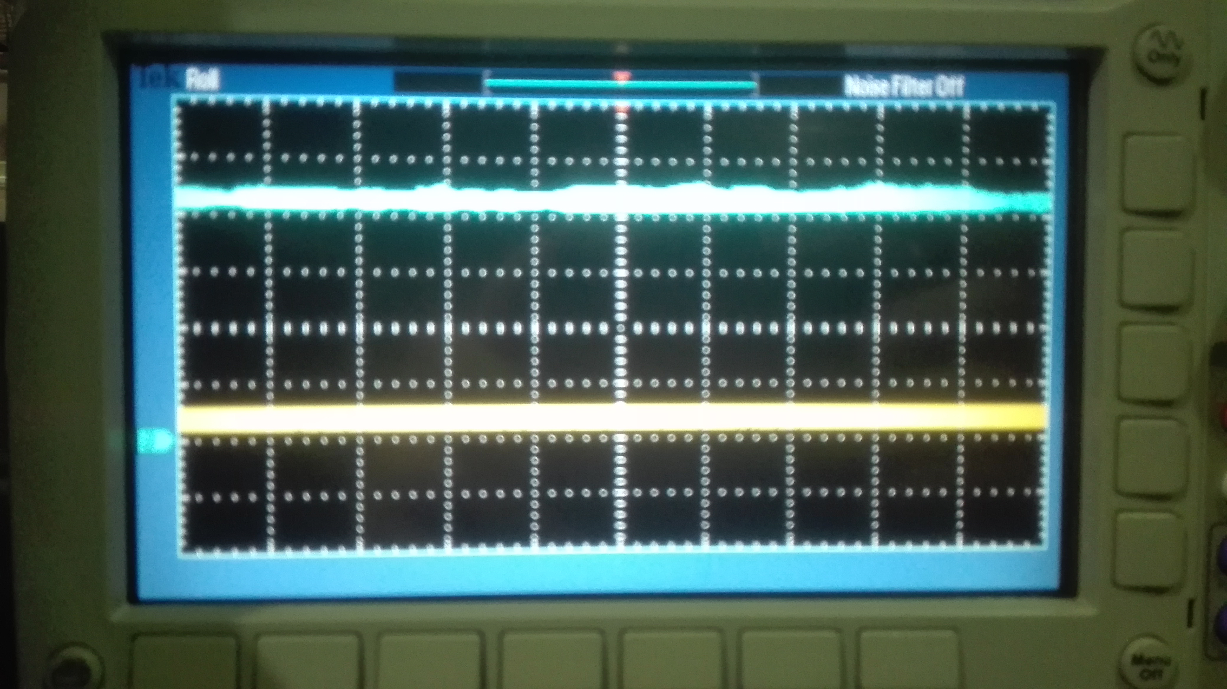
Huge dT guess:
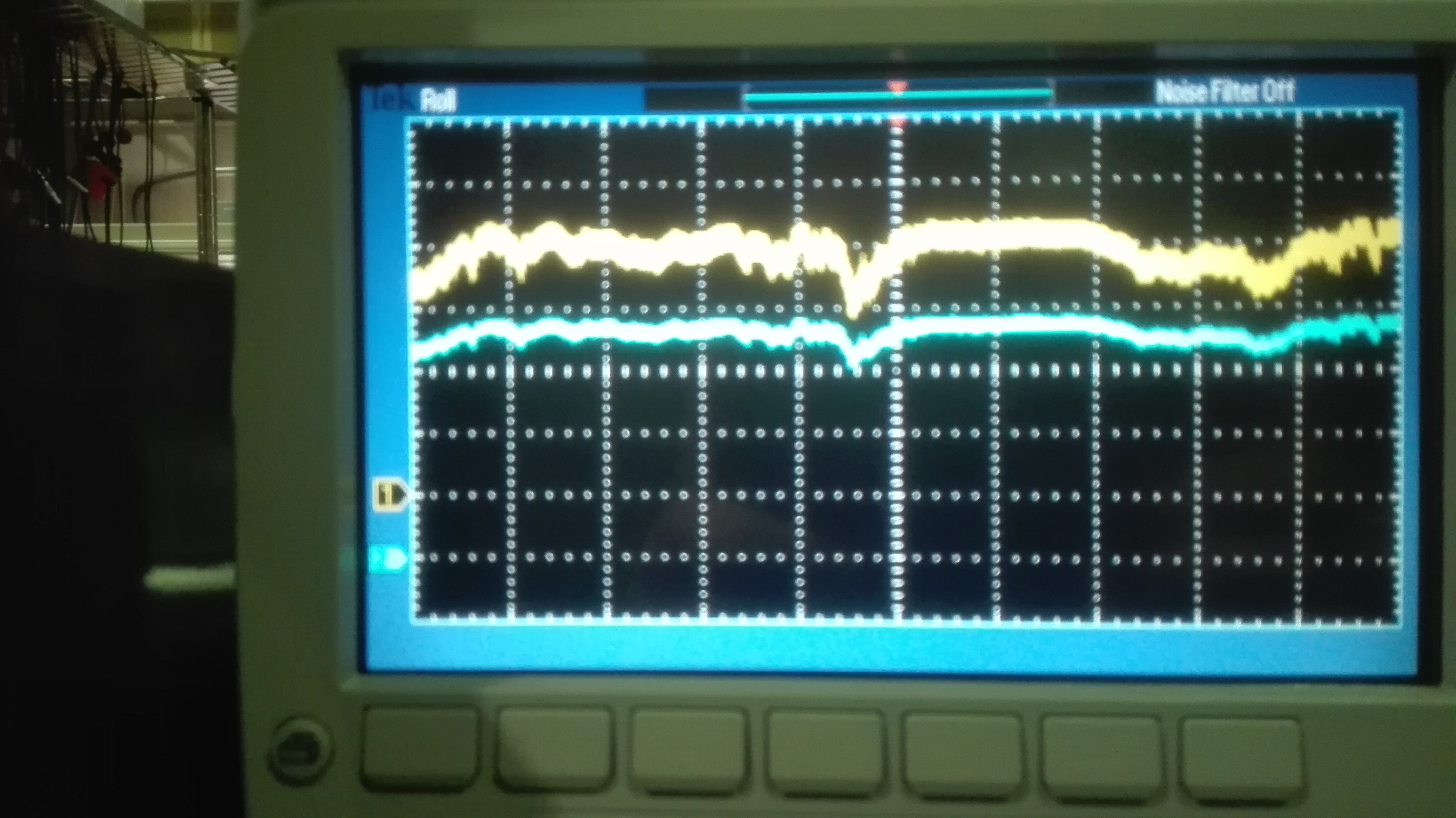
After the previous work, the time strip-chart of the produced green and the SHG IR transmission, as seen by two phodotiode, has been recorded (Fig.8). As it's clear the low freq fluctuation is still present. To better understand what is the dominant factor in this low freq noise the thermal control of the LiNb crystal has been swithed off and the two signals has been recorded again (Fig.9). In this situation (Tcrystal = Troom) the SHG cavity does not produce any green but the transmitted IR si much more stable, therefore we suspect that the crystal thermal control while operating at the phase matching temperature introduces a dT noise that the cavity lenght control is not able to compensate.
We plan to investigate in the next days on the thermal control in order to measure the temperature stability and to improve the temperature stabilization.