Summary:
I soldered a geophone preamp to a geophone and tested it with the cable Aso-san made previously ( http://www2.nao.ac.jp/~gw-elog/osl/?r=47 ) and the IO chassis at the TAMA West End.
Details:
The original geophone connector has been cut off, leaving five individual wires. I used an ohmmeter to identify them:
Red/White - main coil, 5.5 kohm
Blue/Black - calibration coil, 6.8 ohm Green - ground
I traced the pin names from Aso-san's cable through to the preamp:
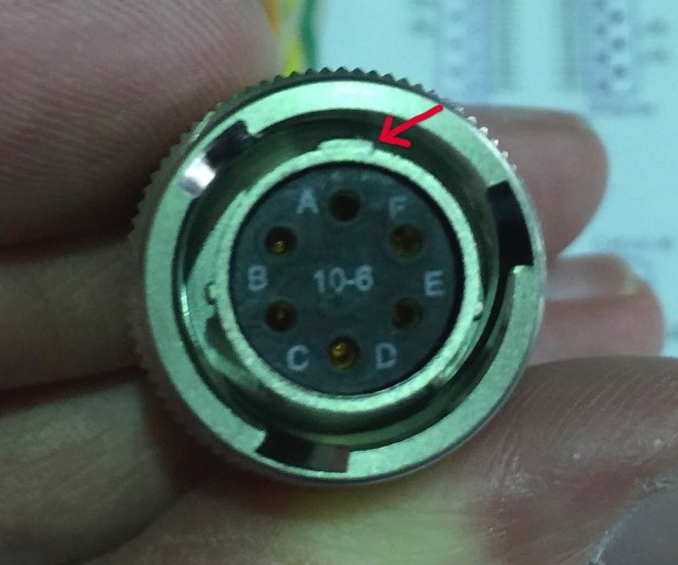
* The Amphenol MIL-DTL-26482, Series 2, Matrix 10-6 plug on the end of the cable is a female. The A pin is labeled and can also be identified as the one near the widest of the three locating lugs. Pins B to F continue anticlockwise. See geophoneplug.jpg.
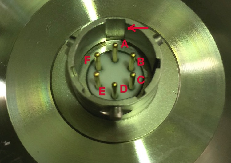
* The Amphenol socket on the outside of the geophone canister end cap is a male. The A pin is near the widest of the three locating grooves, and pins B to F continue clockwise. See geophoneendcapsocket.jpg.
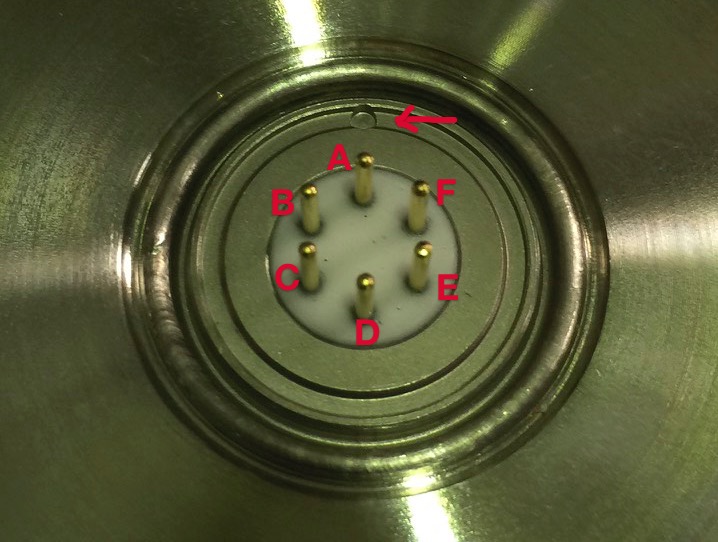
* The six-pin connector on the inside of the geophone canister end cap is a male. The A pin is identified by a dimple in the grove around the pins and pins B to F continue anticlockwise. See geophoneendcaprear.jpg.
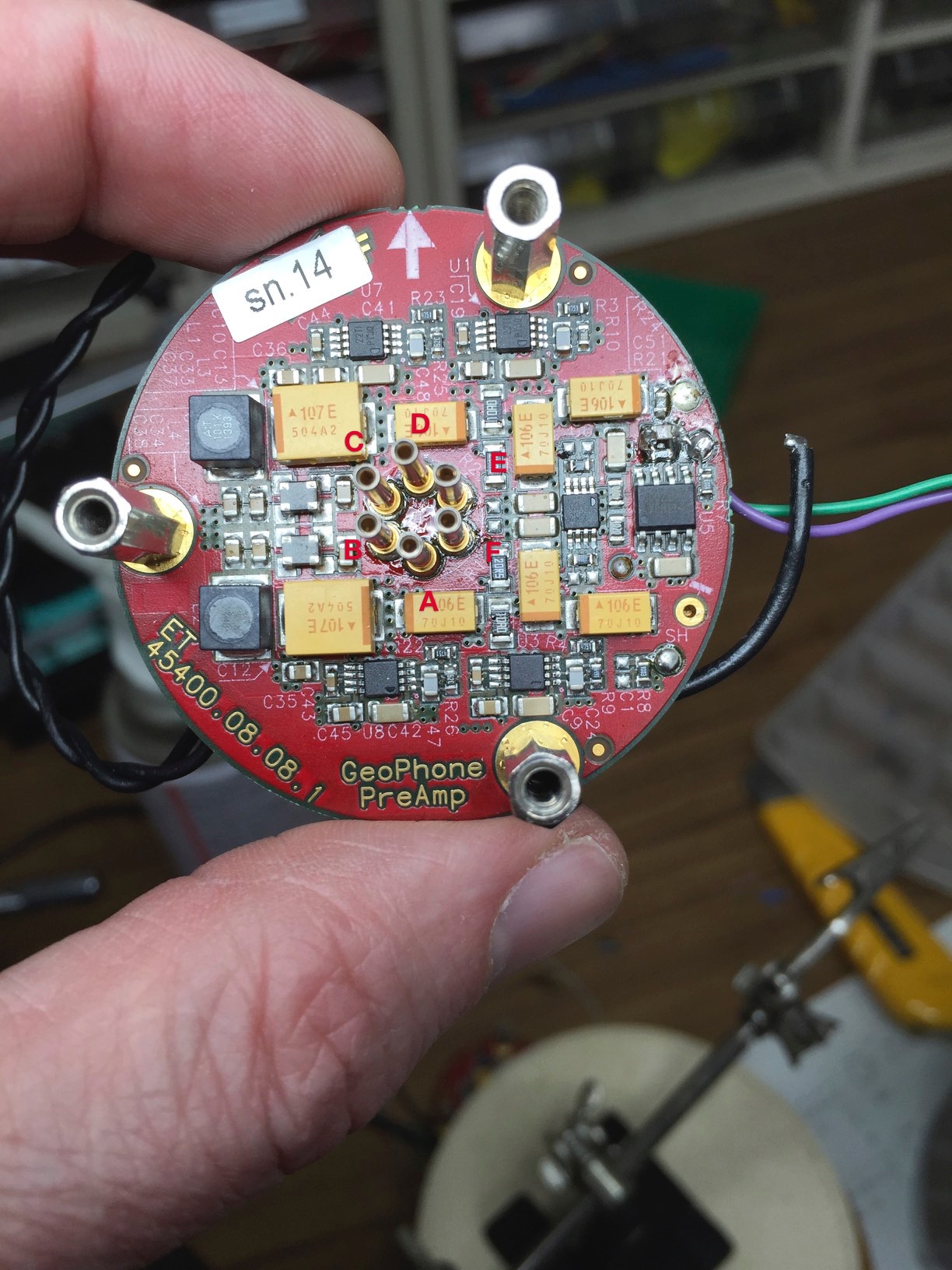
* The front side of the circuit board has six female sockets. When the silk-screen text is right-way-up and the large white arrow is at the top, the A pin is at the BOTTOM! Pins B to F continue clockwise. See geophonepreampfront.jpg.
* The back side of the circuit board is what will be visible in the final stages of assembly. When the silk-screen text is right-way-up, the A pin is at the BOTTOM! Pins B to F continue anticlockwise. See geophonepreampback.jpg.
This means that to assemble the preamp and canister end cap, you should orient the end cap with the dimple at the bottom and place the preamp with text right-way-up.
I then soldered the red lead to the INPUT-GEO terminal, the white lead to the GND-GEO terminal, and the green lead to the GND. This was very awkward because I tried to do it so as to allow later assembly of the canister, which meant the wires needed to pass through the canister flange, with the preamp and geophone stranded on opposite sides. See Geophone Test.pdf. In fact it was so awkward that I think it needs to be redone with connectors rather than soldered joints. However it was good enough to allow a test to verify the connections.
I took the geophone and preamp down to the West End and set it up on one of the optic lever pillars (as a convenient solid platform) using clamps to prevent it moving. I used the geophone cradle for this test rather than trying to get the geophone into the canister body. See geophonetest.jpg
I powered up the geophone distributor in the West End IO rack. I connected a straight cable, a gender bender, the geophone adapter cable and the geophone canister end cap (but not the preamp) as Geophone #0. I checked that the power was reaching the expected pins. I then plugged in the preamp.
Sekiguchi-san had been using ADC channels 4-7 to test some other signals, so I plugged the geophone distributor output into ADC channels 0-3. As expected the geophone signal showed up on one of the LVDT channels.