Summary of yesterday night work (thu 29-->fri 30). The goal was to make a characterization campaign for the cavity lock, in order to make it more stable.
1) Beam stability
In the past we observed an evident jitter of the beam. From a comparison of the spectra we were convinced that this was caused by the residual motion of BS and PR. In the past days we where able to improve the stability by improving the local control filters (a dedicated entry will follow).
We observed that the beam direction (observed by misaligning the input mirror) was drifting and we decided to test a new strategy to keep the mirror position. We change the local control filters in order to avoid to gain at low frequency (we changed a pole at 0.1 Hz with a double zero at 0.1 Hz and we controlled the mirror position not by adding an offset of the loop but simply sending a DC signal to the coils.
We coudn't see a major improvement in the performances.
We also observed the intermittence presence of spikes in the error signals from BS and PR which makes difficult to keep the cavity alignment.
Eventually the old controls (with integrators at low frequency) were restored.
2) Laser servo gain transfer function
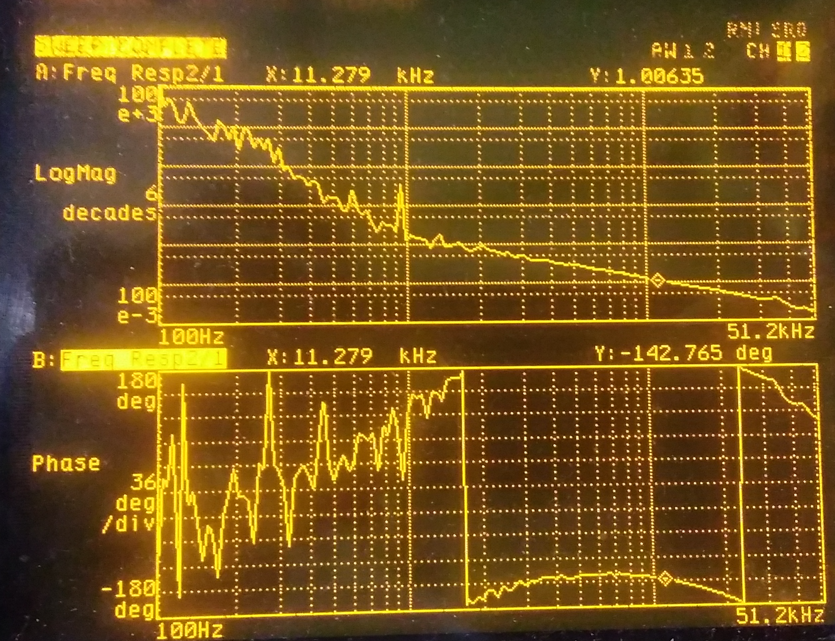
We have set the gain of the servo in order to have ~10 kHz bandwidth. See the transfer function in fig.1. (in 1/f^4 mode)
At a first look, the TF behaves as expected. The data have been stored in the floppy disk and they will be compared with the model. The phase margin at ~10 kHz is about 40 degrees.
The transfer function has been measured with the Agilent 35670A spectrum analyser, with a swept sine with 50 mV ptp.
3) Servo parameters
- modulation depth = 1 V pp at 78 MHz (reduced with respect to before). This should correspond to a modulation depth of m= 0.185 rad.
- LO = 8.5 Vpp at 78 MHz (increased with respect to before)
- Demodulation phase = 111 deg
--> With this data the error signal is 3-4 V ptp, for a transmited signal of ~ 3-4 V depending on the alignment of the cavity (note that we did not checked the green laser power yesterday night)
- attenuation of the input signal =9.1
- PZT gain = 0.7
- thermal control gain = 3
- Threshold on the transmitted signal ~ 2 V
4) Auto-relock
With this configuration the cavity automatically locks when the transmitted power crosses the resonance. When the cavity unlocks, it relocks automatically. Note that the servo is always in the 1/f^4 configuration. The video shows the cavity locked, then the input mirror is on purpose misaligned, then it is re-aligned and the cavity re-locks.
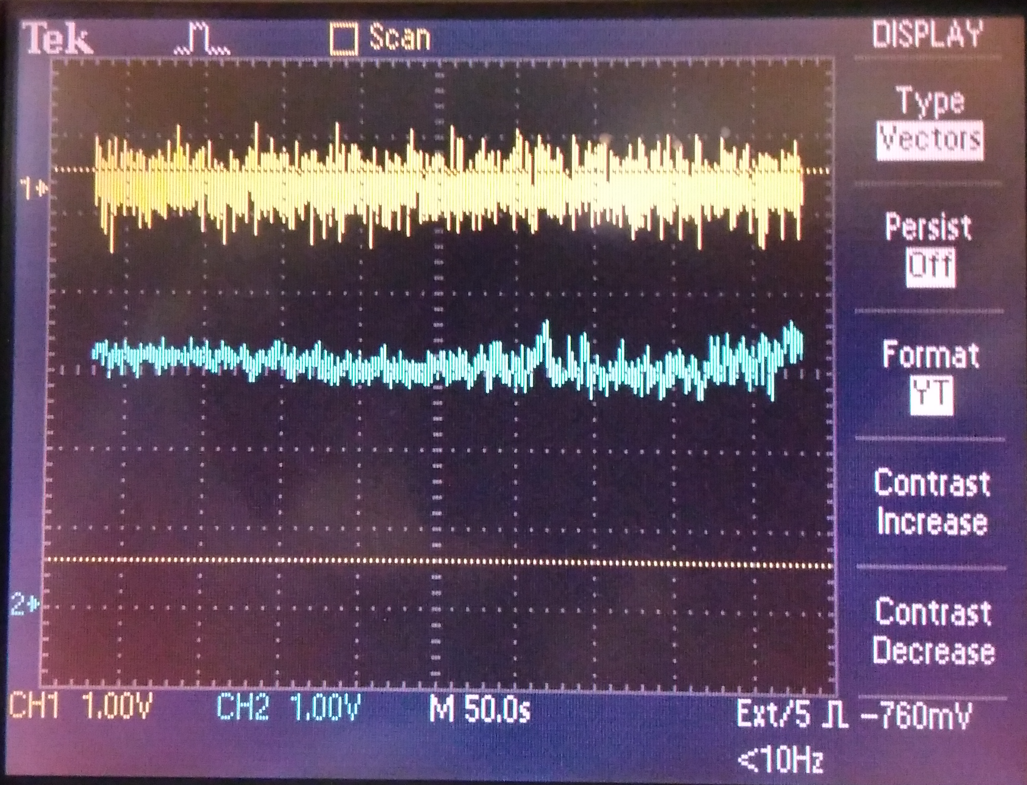
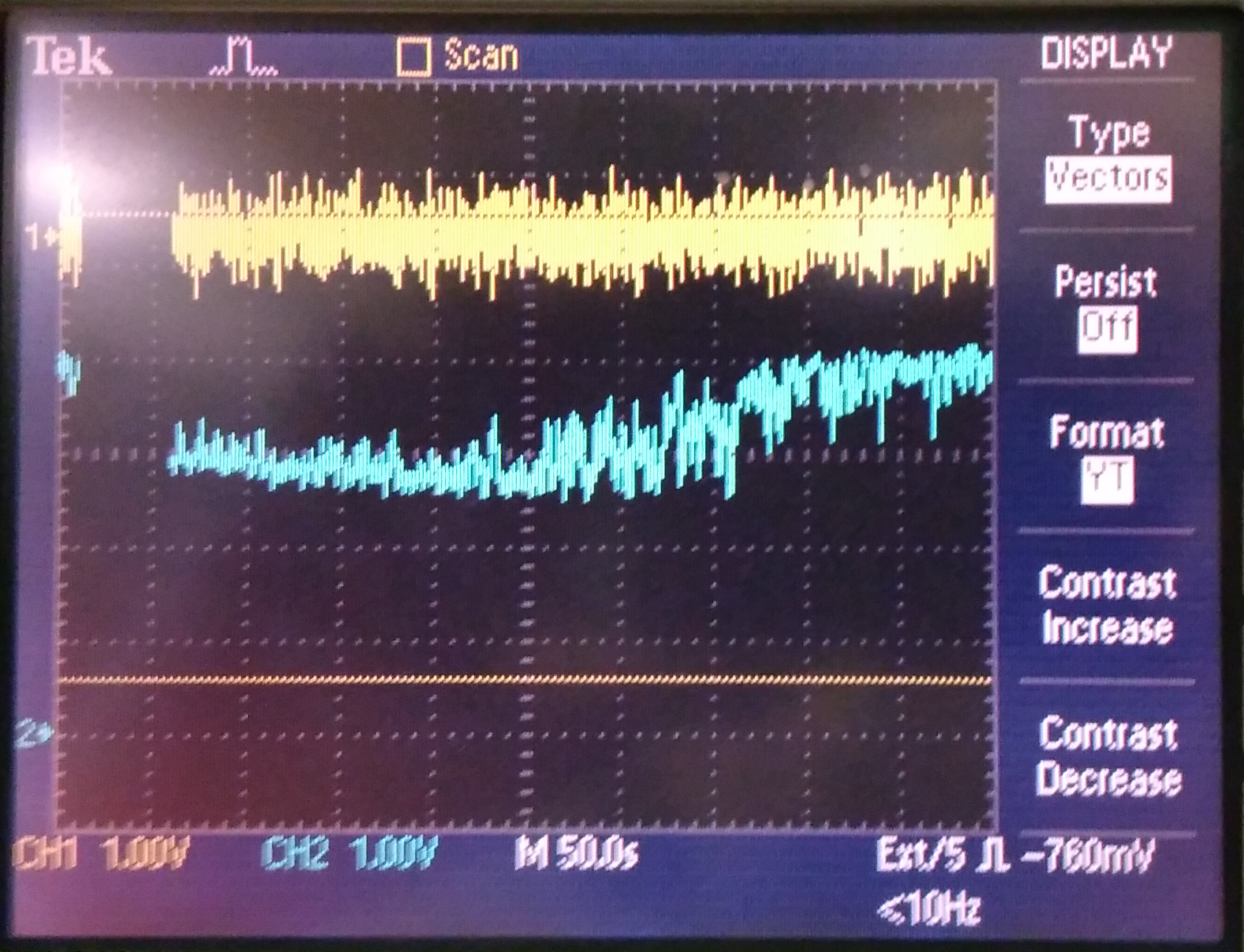
5) Stability
During yesterday night lock the cavity was very stable. The plots 2 and 3 show the transmitted power (in cyan) and the error signal (in yellow) for 500 s. No actions were performed to realign the cavity on the second plot. Max transmitted power was ~ 4 V.