The goal is to scan the voltages of LC1 and LC2 and monitor the generated polarization state for each voltages couple.
LC1 fast axis is at 45deg of input polarizer and LC2 fast axis is at 0 deg of input polarizer.
The polarization state is scanned by rotating the output polarizer rotation by 5 deg increment from 0 deg (cross polarizer configuration) to 180 deg.
Labview modifications :
In order to somewhat efficiently scan our voltage space parameters, we modified the 'Sawtooth Formula Voltage Theta' subvi to scan our parameter space.
We can apply 1 sawtooth to each LC voltage controller with a user defined phase shift and frequency ratio. Below we used a 11:12 frequency ratio with 0.5 Hz frequency applied to LC1 (11/12*0.5Hz for LC2).
They are each doing 10 periods and then the output polarizer is rotated by 5 deg.
Analysis :
The data are stored in 2 files : one from rotation angle of 0 to 90 deg and one from 95 to 180 deg.
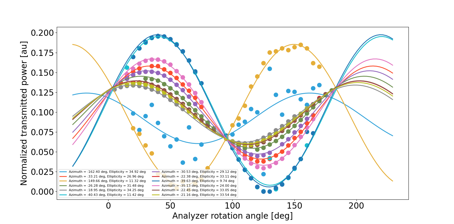
All the data are combined, voltages are rounded to 0.1V and for every couples (V_LC1,V_LC2) if there are at least 25 rotation angles values, the data are further processed. More precisely, the normalized transmitted power is fitted by P(theta) = a/2 * ( 1 + cos (2*ellipticity) + cos (2 * (theta - azimuth))
In the fit, the initial guess of the azimuth is given by the rotation angle with maximum transmitted power.
You can see some results in the attached figure (in total we have 1161 couples that meet our requirements).
next steps
I would like to replace the sawtooth scan by a step function scan to avoid the 0.1V rounding.
It could be useful to optimize our Lissajous scanning coefficients