This elog is about issues with setting up the RF switch in the attempt of improving ringdown.
Details:
1. After I installed the RF switch (The output of the RF driver was fed as input to the switch. The output of the switch was fed to AOM), the PD at the transmitted beam was not able to detect any power or modes during the laser scan. I checked the diffraction efficiency of AOM after RF switch installation and saw that it dropped from 40% to 7%, and as a result, the transmitted beam power was affected too.
2. To check the above issue and confirm that it happened only after the RF switch installation, I removed the RF switch and checked the diffraction efficiency again, and it was back to 40%. The PD at the transmitted beam also could see the modes during the laser scan, and lock normally.
3. I didn't change any scale for observing the transmitted beam in an oscilloscope or PD settings, after the installation of the RF switch. For now, I don't know how to resolve the issue.
The observations made during this are as below:
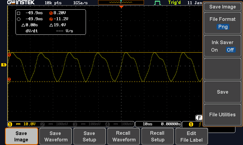
4. The RF switch was kept on the table and because of touching the plastic surface, it showed an excess voltage (19 Vp-p). (Fig 1)
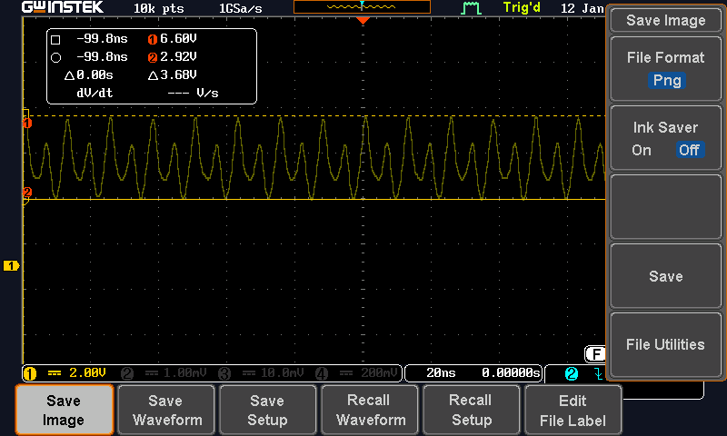
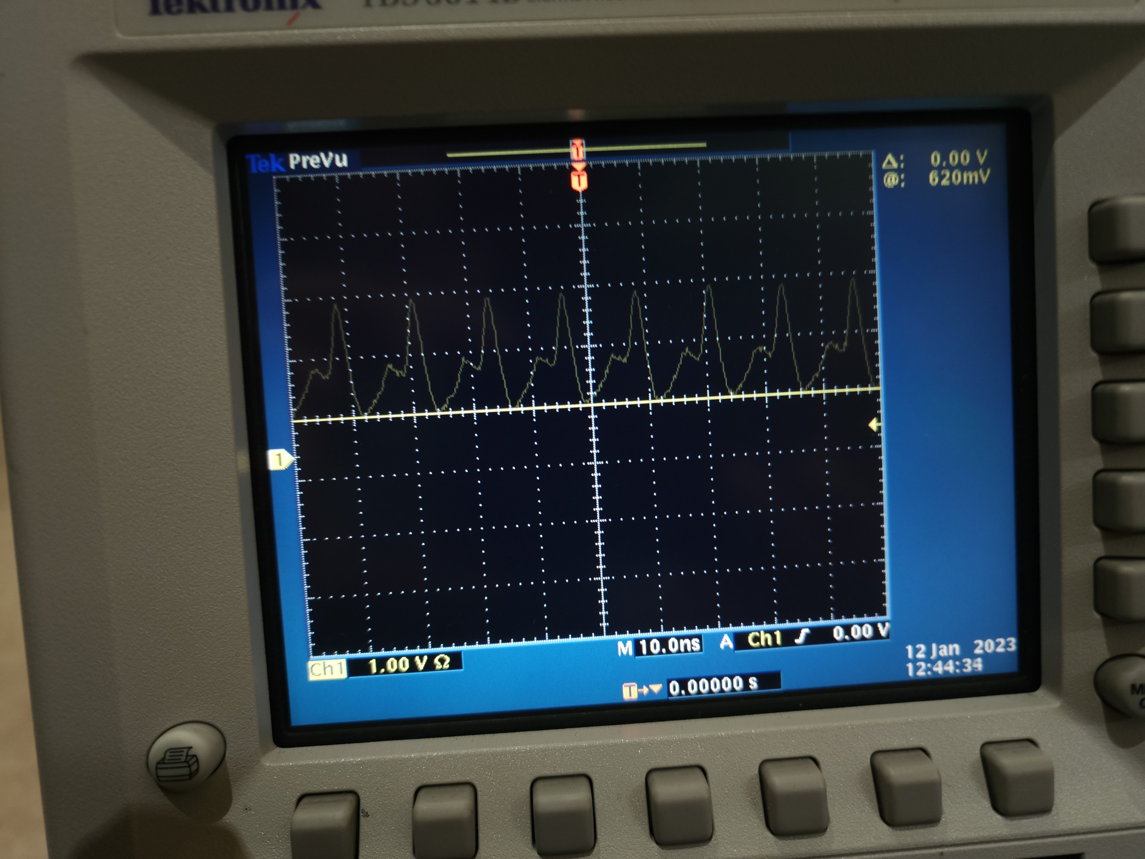
5. I removed the RF switch and now it doesn't touch anything now, the voltage observed is now 3.68 Vp-p (Fig 2). Although Fig 2 is from an oscilloscope of 1MOhm, the distorted signal is also observed in a 50Ohm oscilloscope (Fig 3).
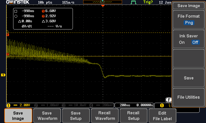
6. The response of the RF switch when I make the TTL 5V (The Out1 shuts down when I make TTL 5V(or >2V) (Fig 4).
Next Step:
1. Look for the specifications of the RF switch
2. Analyse the signal from the RF driver to understand distortions in Fig 2 or 3.