Yuhang and Michael
We set up the OPO in the reversed configuration (incoupler mirror on the side of detection power meter) and generated green from the OPO. Then, the OPO was locked, and we attempted to measure the generated green power as a function of crystal temperature to find the optimal phase matching working point.
However, we didn't get very much power. Looking over a range of thermistor resistances 5 - 7.5 kOhm, we expected to see a large peak of generated green power somewhere, but the most we got was 42 uW on the detection power meter (Yuhang thesis fig 4.26 shows 110 mW of green near 7.3 kOhm resistance and a smaller 83 mW peak near 6.7 kOhm). Before the measurement we removed some ND filters before the input FI, and early in the measurement we removed an unnecessary beam splitter in the laser path then realigned the OPO. But, it looks like the internal alignment is quite bad now, compared to 3006, probably just from removing those optics.
Yuhang and Michael
It was found that after flipping OPO, the alignment of OPO got worse and was hard to recover.
Today we checked again the alignment of OPO. We conclude that it is certainly that the flipping of OPO makes alignment worse. This is because that the mode matching condition is very much different depending on which side the laser enters OPO.
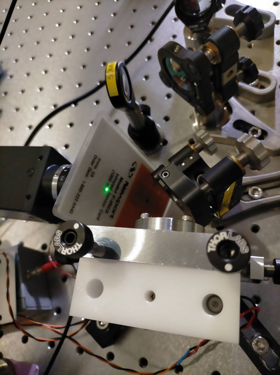
It was always questioned how we can make sure a good internal alignment. In fact, the alignment procedure of OPO is not so much different from our filter cavity. The only difference is that we cannot control the angle of OPO reflection surfaces as easily as the filter cavity mirrors.
For OPO input surface, we adjust injection beam to make injection and reflection overlap. But at the same time, we need to make sure the crystal transmission has a good shape.
For OPO end surface, we adjust input-coupler surface position to find interference.
At this step, the alignment is not optimized but we need to fix the input-coupler. Then we need to optimized mode matching. When optimizing mm, we need to pay attention to which lens is more sensitive. Pay attention also that after moving a lens, we basically just need to move the tilt of one steering mirror to recover alignment and compare the new mode matching HOM to understand if the mode matching is getting better or worse.
After optimizing mode matching, if there is still misalignment. (It was found that misalignment level is different when optimizing mode matching) We need to adjust input-coupling mirror.
The attached two figures show two situations: 1. after optimizing mode matching, before final alignment of input coupling mirror 2. after final alignment of input coupling mirror
There is still space to further optimize OPO alignment. Note that the OPO transmission power is increased in Fig.2.
Yuhang and Michael
After the OPO alignment optimization, it was found that PDH signal was lost. Today, we found what is causing this problem: the OPO transmission PD is misaligned (drop from more than 5V to ~50mV). After aligning OPO transmission PD back, the PDH signal is recovered. (It was checked that the signal sent to EOM is 2Vrms, according to logbook2469, the modulation strength is 0.1-0.3rad/V, so we should have a modulation of 0.2-0.6rad. If we have 0.6rad, we should see about 10% power drop from carrier. If we have 0.2rad, the power goes to sidebands should be negligible. the modulation should be almost negligible since we didn't observe a power decrease after sending modulation)
Then we measured OPO generated green power as a function of OPO temperature. The measurement offset power on power meter is 3.3uW. We take measurement from temperature controller reading 7.7kOhm to 6.5kOhm with a step of 0.02kOhm.
These are the measurements results
| 7.700 | 7.680 | 7.659 | 7.640 | 7.620 | 7.601 | 7.579 | 7.560 | 7.540 | 7.519 | 7.500 | 7.480 | 7.459 | 7.440 | 7.420 | 7.400 | 7.380 | 7.361 | 7.339 | 7.320 | 7.299 | 7.280 | 7.260 | 7.240 | 7.220 | 7.200 | 7.179 | 7.160 | 7.140 | 7.119 | 7.099 | 7.080 | 7.059 | 7.040 | ||||||||||||||||||||||||||
| 93.0 | 93.4 | 94.0 | 94.3 | 94.5 | 94.6 | 94.6 | 93.8 | 94.2 | 93.7 | 94.6 | 96.0 | 97.7 | 99.8 | 102.2 | 105.3 | 109.0 | 112.5 | 116.8 | 120.5 | 122.8 | 123.0 | 120.0 | 114.5 | 106.9 | 99.0 | 92.5 | 87.0 | 81.7 | 77.6 | 73.0 | 68.7 | 65.0 | 62.6 |
However, during this measurement, we found that the OPO lock was having some issues due to the disturbance from temperature change while OPO kept locked.
Thus we performed again the measurements with a OPO unlock/lock between each measurement. This new measurement didn't have locking issue and will be reported later as a comment to this logbook.
Here is a set of data points measured for generated green power versus thermistor resistance. The PDH lock was optimised at each temperature change. Note that only about 200 µW of infrared is sent to the OPO. The gap was just due to a note taking error, so we will fill out the rest of the points soon.