I repeated the measurement of entry 289, but this time, I put the tama-size sapphire sample in a position such that the probe beam is crossing it but the pump beam is not, so I avoid any back reflection of the pump. I also correct the position of the Image Unit according to the formula I wrote in entry 290.
I moved the base micrometer by the distance L x (n-1)/n - 1mm away from the sample. L is the path inside the sapphire sample, which is the thickness 60mm divided by cos(6°), 6° is the probe incidence angle, n is the sapphire refractive index 1.76. Therefore the displacement is 25.05mm
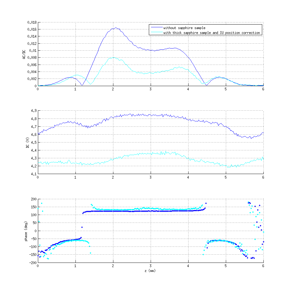
The attached plot shows the comparison of the two scans.
The result is not as good as in the simulation. The DC is different because there is an additional reflection when I put the second sample, but the AC/DC should be equal in the two cases.
I think I have to figure out why. Maybe the positioning should be slightly different, so I will try to find he optimal position.
According to the basic theory of the PCI method, the heated area of the sample makes a phase shift in the probe beam; this perturbation is small and can be treated as a gaussian beam which interferes with the main beam; the maximum of the interference is detected when the PD is at the Rayleigh length of the gaussian perturbation, which can be calculated using the waist of the perturbation, which is the pump beam size.
The approximation of the perturbation to a gaussian beam is valid at first order, but for a fine tuning of the detector position, it might be not a good approximation. I consider this because, when I correct the position for the thick sample (as in elog entry 291), I notice that the calibration value is not the same (as expected from the simulation). A possible explanation might be that when I put the thick sapphire sample and correct the Image unit position, the detector is not in the interference maximum anymore. So, I maximize the signal as a function of the detector position experimentally, by moving the Image Unit with the micrometer screw. I do it for the reference sample alone, and for the reference sample with the sapphire sample behind it. Then I compare the two maxima positions in order to find the best position correction for thick samples.
First two plots show several scans of the reference sample for each position of the Image Unit, with and without tama sapphire sample. In last plot, I took the middle value of each scan and plot it as a function of the Image unit position. 35mm is the closest position of the IU to the sample, 0mm is the furthest IU position. To move it further it's necessary to unmount the IU micrometric translation stage. The theoretical distance between the maximums is 26mm. and the maximums should have the same value.
The plot shows maximums position accuracy of about 5mm, but in the case of reference + tama sapphire, it's not clear wether the maximum is below the position 0mm on not. The problem is the maximum value, it should be the same but for the reference alone the value is 0.1 and in the other case is 0.04. More than a factor of 2