Michael and Yuhang
After the in-coupling mirror cleaning as reported in elog2774 and elog2776, we tried to close OPO again. Apart from mirror cleaning, this time, we tried to align OPO better than elog2769. To make sure a good crystal alignment, we paid attention to:
1. Making sure the flatness of laser beam in pitch/yaw direction using alignment tools such as rulers. Use power of few milliwat now.
2. Change to less than microwatt. Making sure camera is at good height and angle. Mark the beam position on camera by drawing a circle for the laser beam shown on TV screen.
3. Change back to few milliwatt. Putting OPO crystal part on rotation stage with HR side facing laser. Checking injection/reflection overlapping and transmission reaching the circle on TV screen. If not, adjusting by hand the position of OPO crystal part.
4. Adjusting camera lens to zoom in and inspect the image of crystal transmission. This image should be a circular spot without any clipping. If not, consider to adjust the position of OPO crystal part in transversal, longitudinal and tilt DOF.
5. Fixing OPO crystal part on rotation stage gently. In my case, the OPO didn't move after this. If it is moved a bit, bring it back by adjusting rotation stage. Be careful that the longer side of rotation stage should be aligned with laser.
6. Putting in-coupling mirror part of OPO and half-fixing it. Half-fixing means that the screws are ~20 degrees before the feeling of tight screws. This is to make sure that we can adjust in-coupling mirror while keeping it not going to far after each adjustment.
7. Zooming out camera to find roughly the flash of OPO cavity. When zooming out, we can see the inner cavity reflection more clearly.
8. Moving incoupling mirror by hand in horizontal direction to make inner cavity reflection good for horizontal. Moving vertical adjusting screws to find flash.
9. Zooming in camera to see the Hermite-Gaussian mode of OPO cavity. The scan speed was set to be 3Hz.
10. Adjuting finely the incoupling mirror position until the mode shape looks to be good enough. In the end, maybe there is still some residual modes. But it will be fine.
11. Change power to few hundred of milliwatt. Putting a BS before camera and direct the light to a PD to see cavity scan spectrum on an oscilloscope.
12. Fixing in-coupling mirror by the sequence of diagonal so that the alignment can be less affected.
13. Adjusting the injection laser to finalize the alignment.
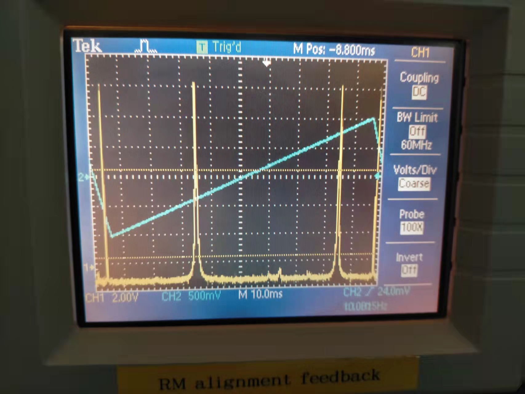
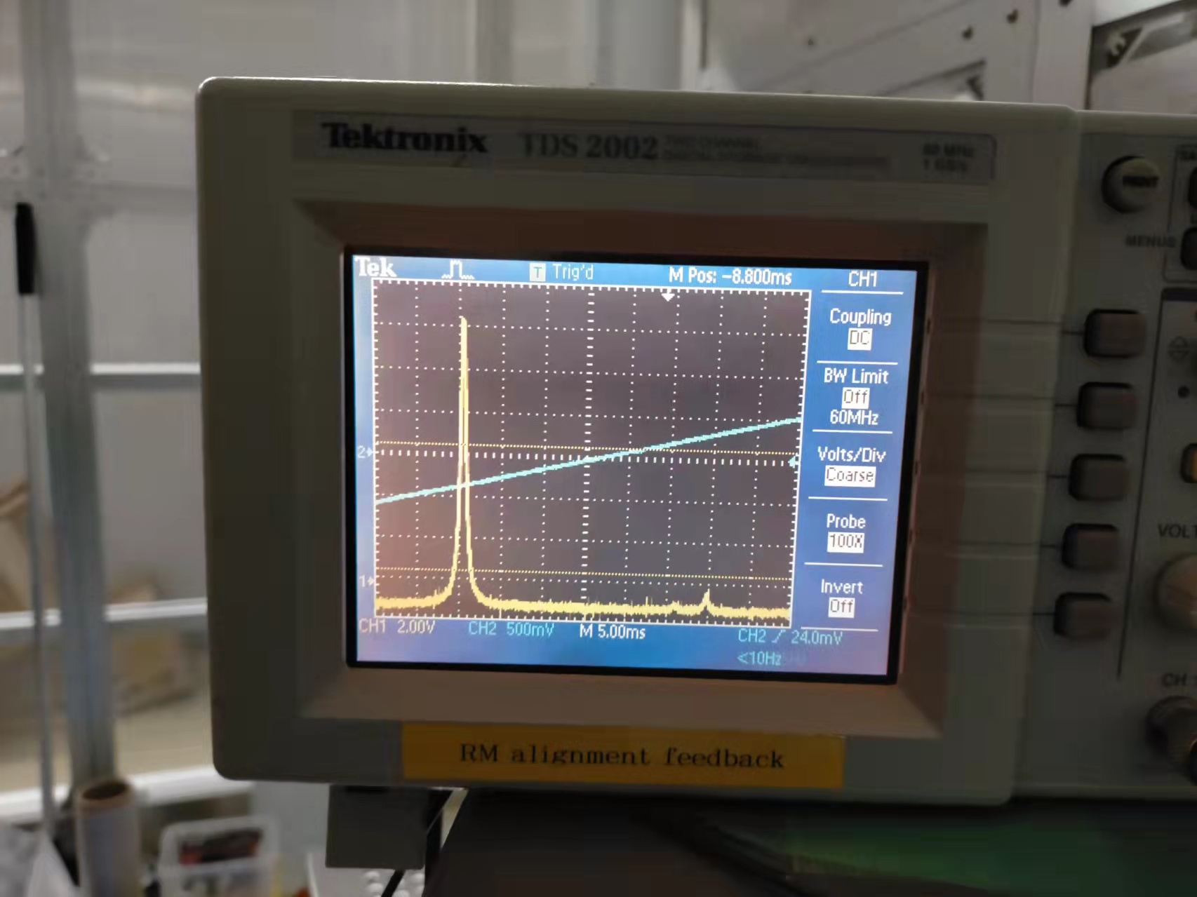
After doing this procedure, we got OPO cavity scan spectrum as Fig.1. The zoom-in of TEM00 is Fig.2. We haven't characterized how much power is on higher order modes. But it looks decent for us.
The camera used in this set-up is found to be tilted today. Fig.1 shows that this tilt is introduced through the interface between camera and post.
During the alignment, we use camera to characterize cavity HG modes shapes. When the beam and camera height is aligned, we found beam appears not in the center of screen as Fig.2. We suspect the tilt between camera and post is the cause of the cavity modes mis-center as Fig.2.
Note that Fig.2 shows the non-ideal alignment of crystal, which has a black defect.