Yuhang and Michael
This is a followup to the issues discussed in 2769.
The OPO cavity was aligned and we attempted to optimise the mode structure of the transmission spectrum. However, there were two second order HOMs we could not get rid of by altering the input steering mirrors, and inspection of the transmission camera showed a lot of scattered light around the main beam.
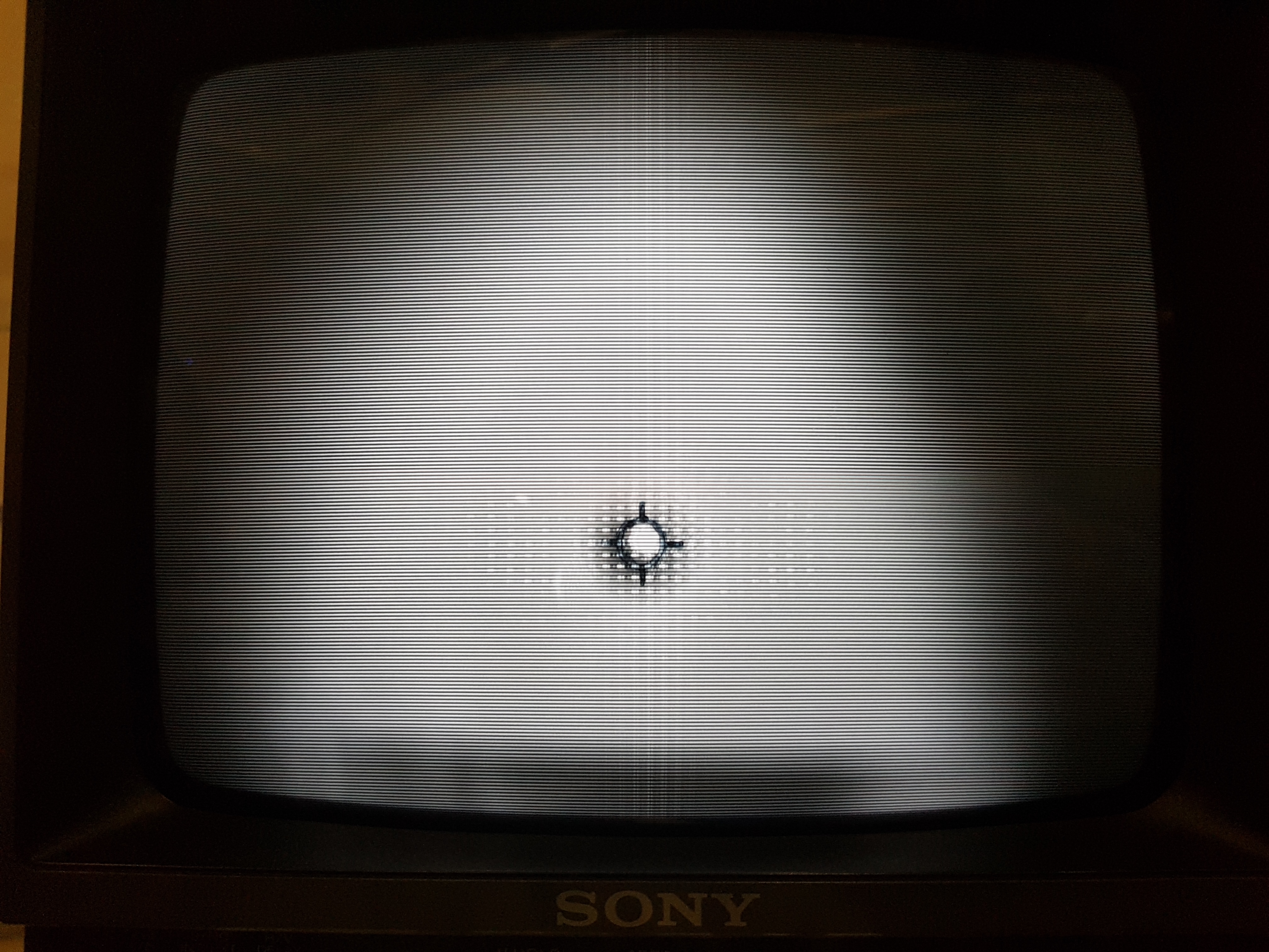
Today, when we looked at the setup, we saw a lot of dirt on the incoupling mirror, which was visible when shining a phone flashlight below it. So we took it out to apply First Contact on both sides. At this point, we also saw a mark from the rubber o-ring that was mounted on the mirror. There may be some inspection needed for the OPO as well. However, I do not personally recall seeing the scattered light problem when the OPO was being aligned without the incoupling mirror, the most I remember seeing was something like a diffraction pattern (attached figure).
We were also in doubt of the position of the OPO inside the holder apparatus. There is some freedom in the beam propagation direction with respect to the OPO placement inside the holder, and there was no specific instruction given in the assembly directions. Given that the beam size required is extremely small , it seems like there would be strict mode matching required here, and yet we also did not see any LG modes when scanning the cavity.
For now, we applied clear First Contact to both sides of the incoupling mirror. We also want to redo the OPO alignment. Most of previous works have ensured the beam propagation axis is very closely aligned to the OPO axis. But, the incoupling mirror position was not that finely adjusted last time.For example, if the beam is hitting the incoupling mirror off-center while not passing through the center of curvature, the wavefronts will not be perpendicular to the curved surface of the mirror, so there will be mode mismatch introduced. The micro adjusters for the incoupling mirror only adjust transverse x and y position, not tilt. So we should optimise the beam position on the incoupling mirror, and then for locking make fine adjustments to the input beam steering mirrors.