Yuhang and Michael
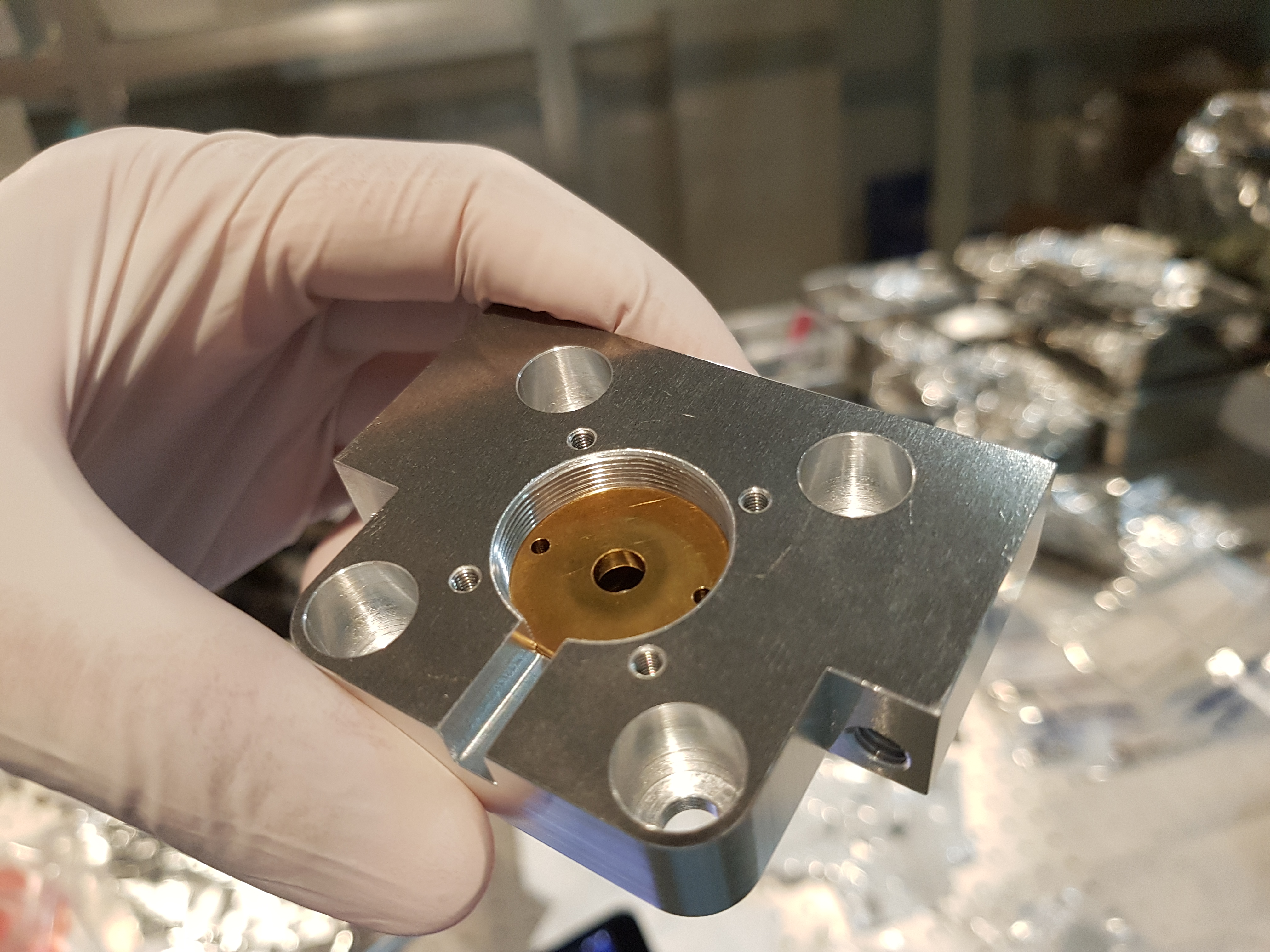
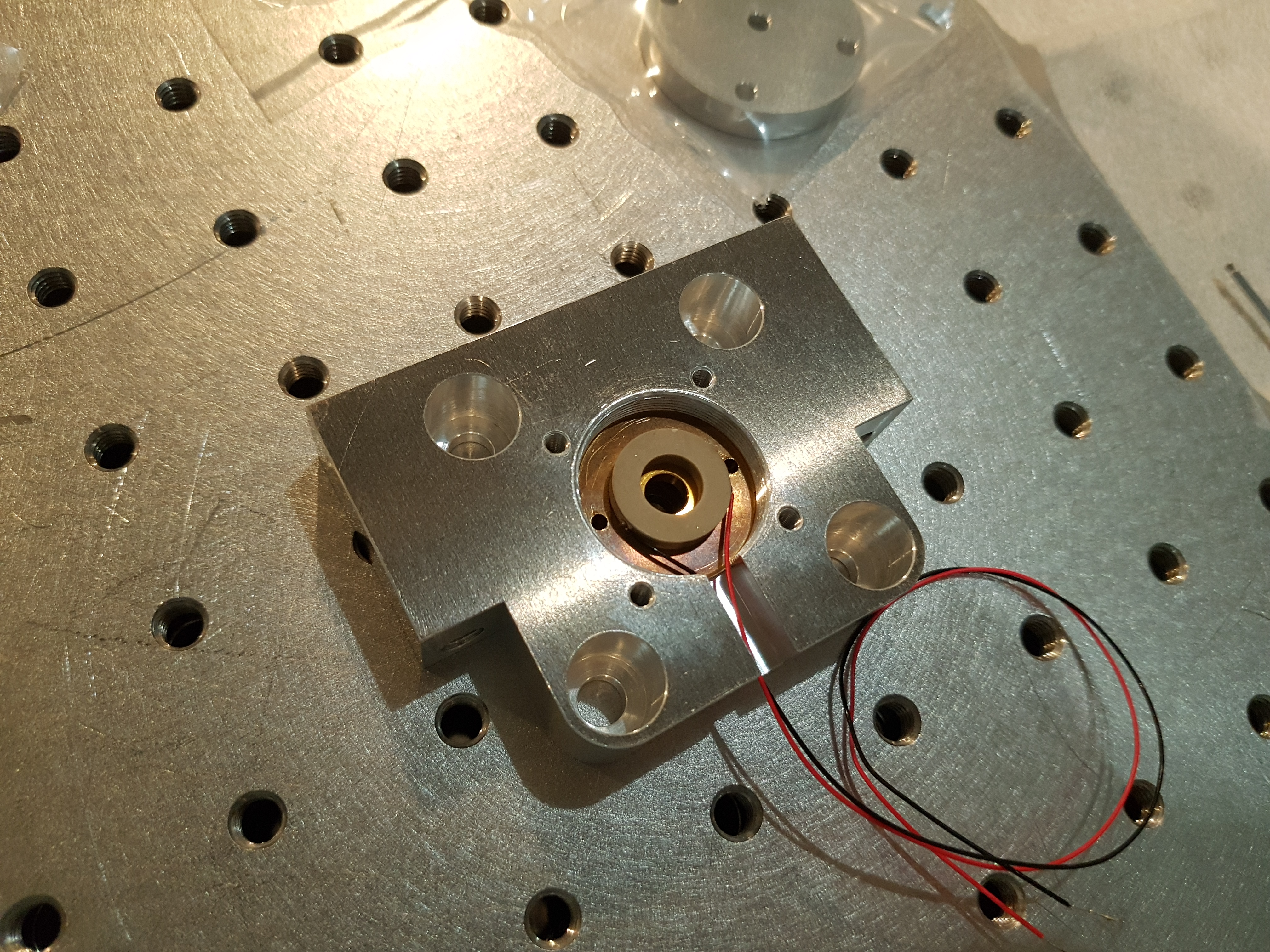
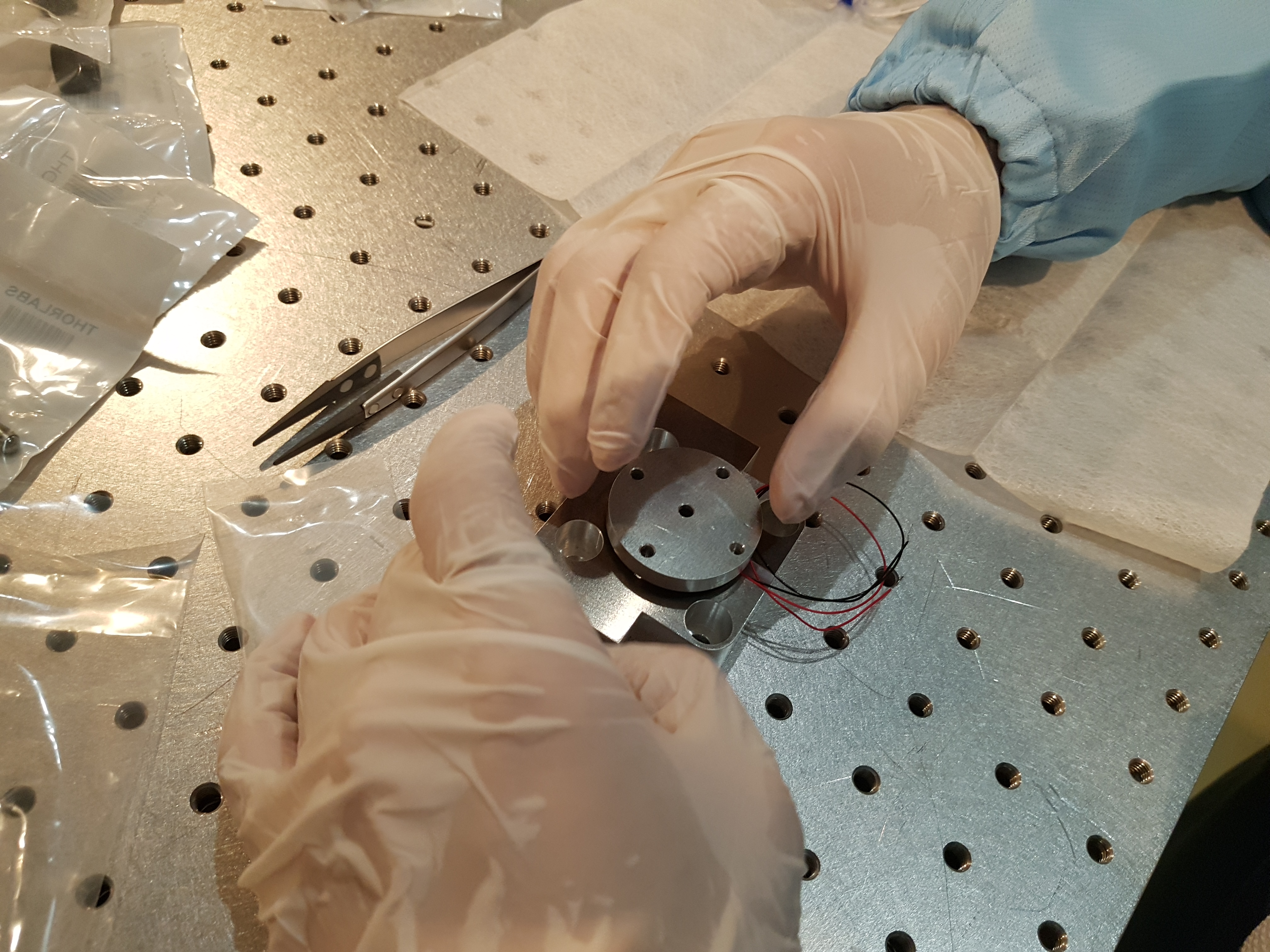
We assembled the input mirror assembly for the OPO cavity as per 812. The only thing to mention here is the orientation of the input coupler convex surface (fig 4 and 5).
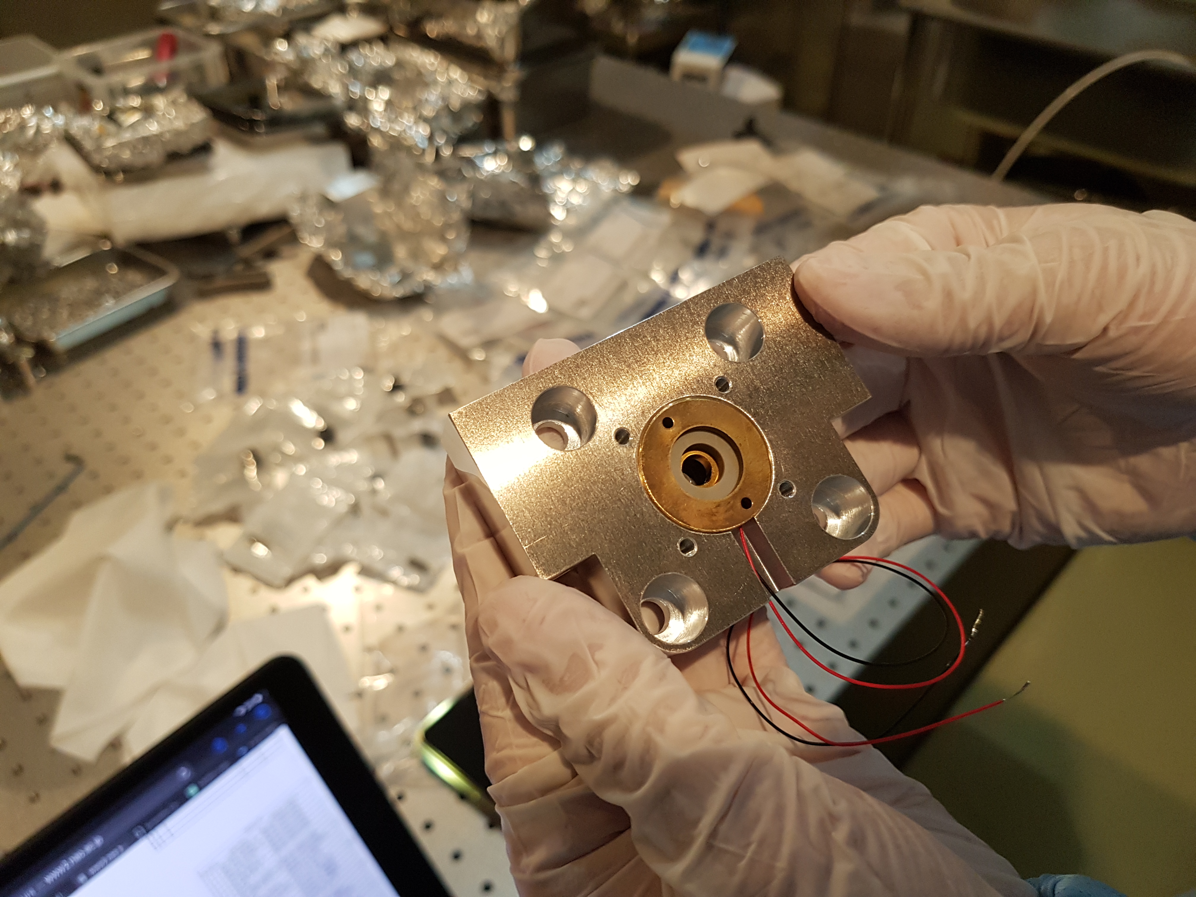
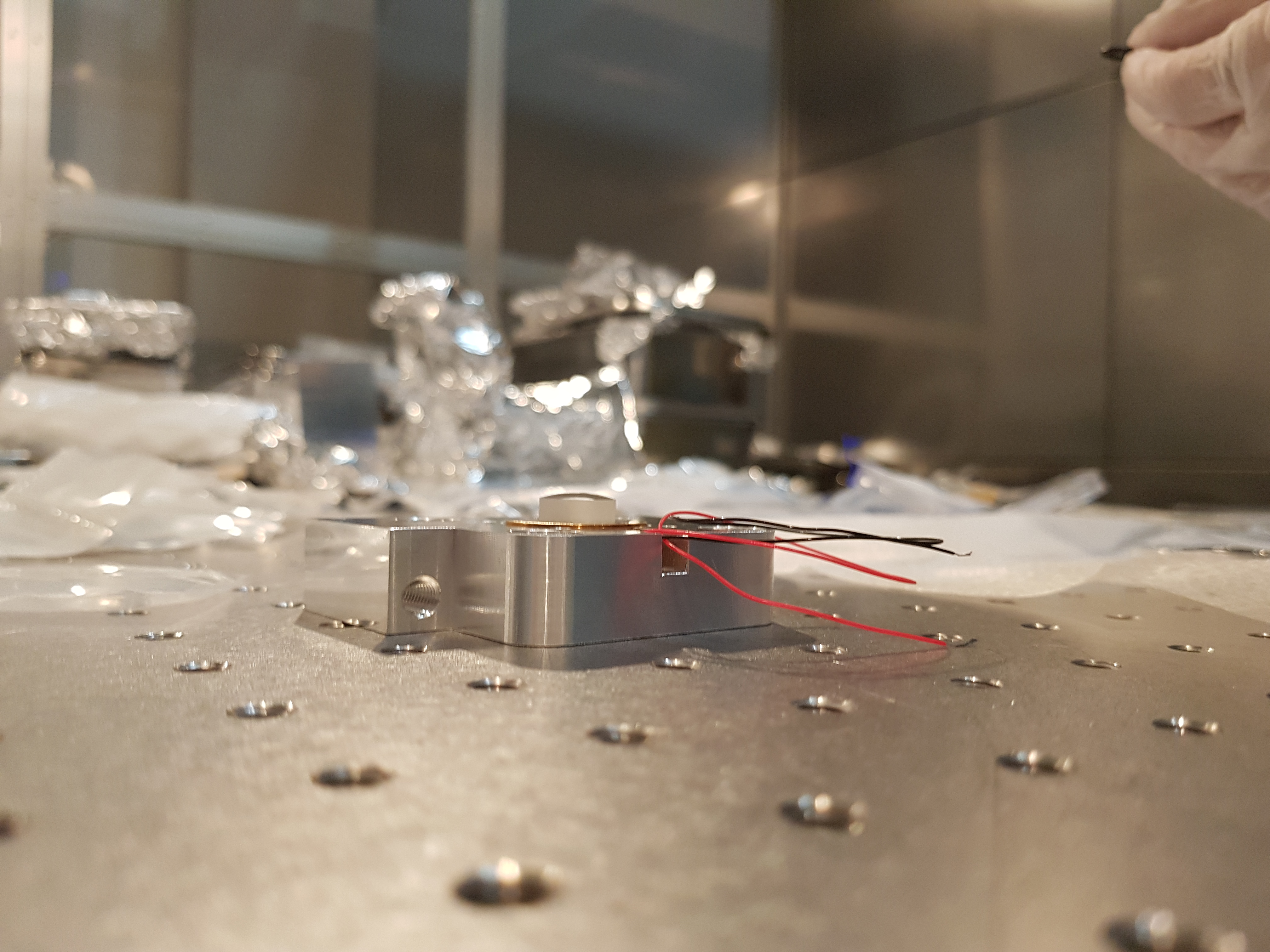
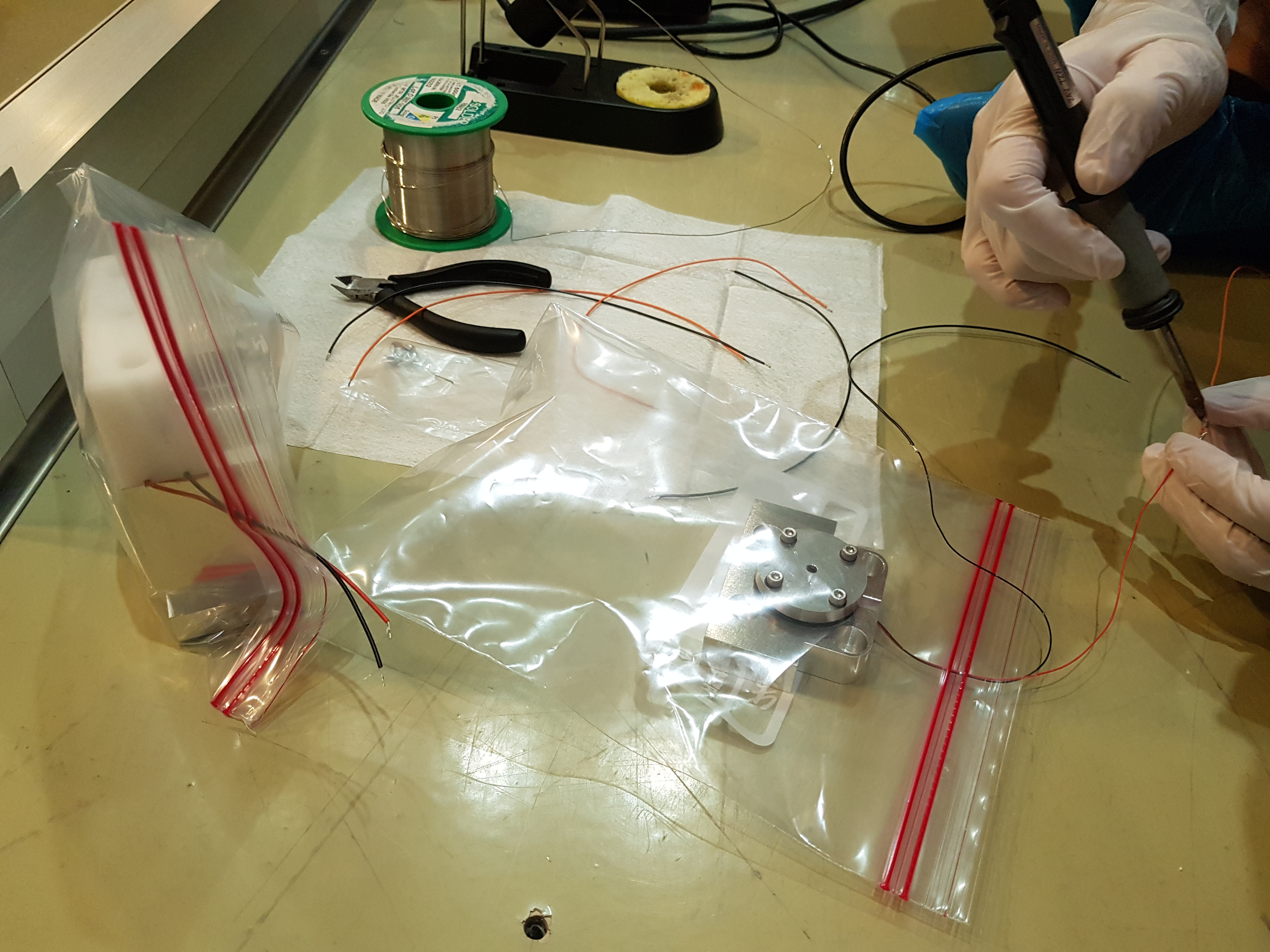
We then connected the interface electronics for controlling the Peltier, thermistor and piezo. The Peltier, thermistor and piezo each have two connecting wires that must be soldered onto whatever means we are using to connect them to their controllers. We soldered these onto a PCB connector. The Peltier and thermistor are connected to a DSub-9 cable going to the Thorlabs temperature controller (Peltier +ve pin4, -ve pin 5, thermistor +ve pin 2, -ve pin 3). The piezo wires were soldered to a LEMO F port.The connecting wires had to be soldered outside the cleanroom - the OPO cavity and input coupler assembly were placed in plastic zip lock bags and sealed so that only the wires were coming out (fig 6). This way they could be protected from fumes and dust.
The Peltier and thermistor were tested using the temperature controller. We saw that we could stabilise the resistance to ~10 kOhm. The piezo also made the expected high-pitched noise when it was actuated (~ 2 kHz test signal).