Yuhang and Michael
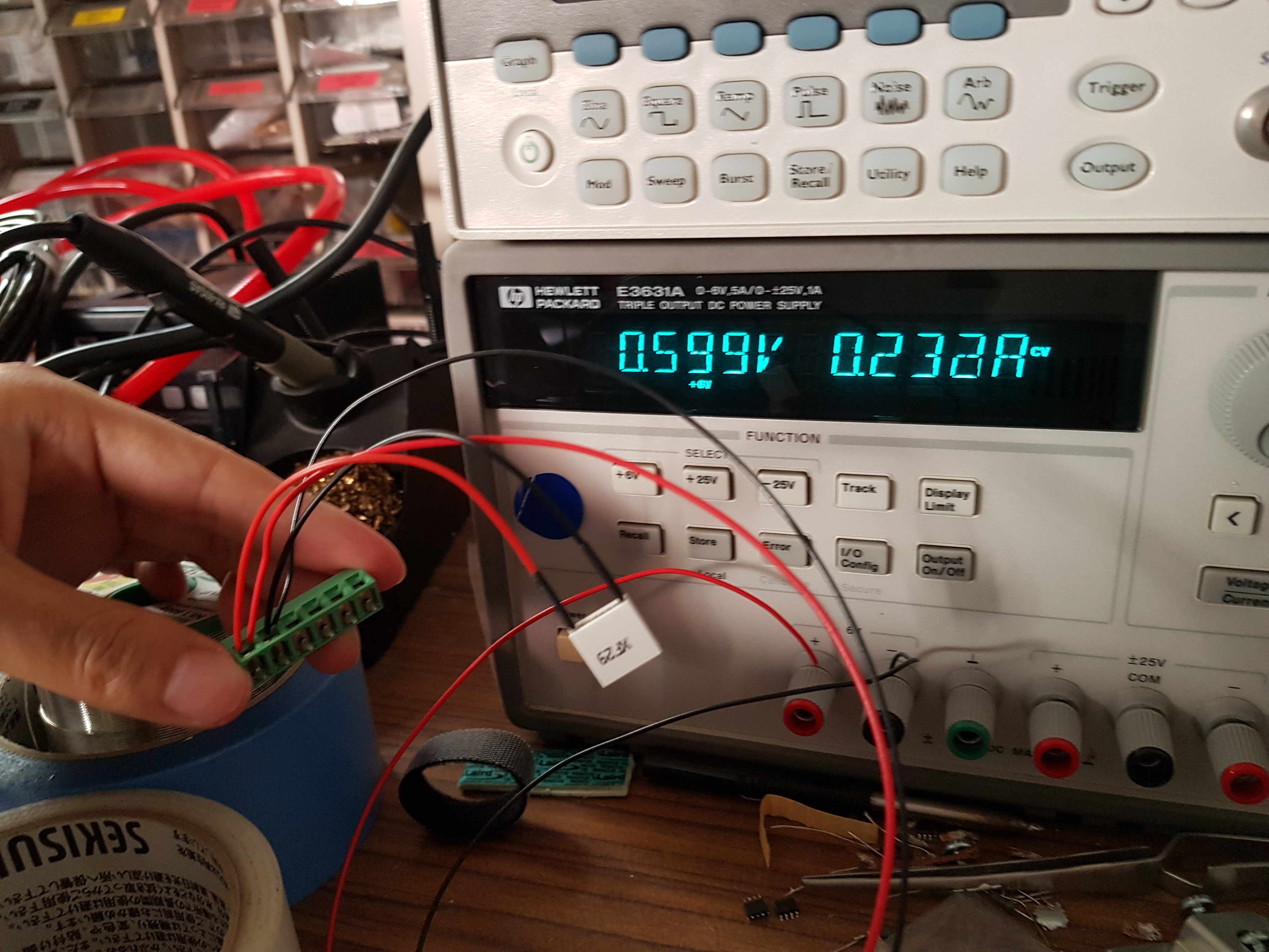
We completed assembly of the OPO crystal holder. We followed the intstructions from 812, although we were unsure of the orientation of the Peltier and tested it by applying a small (< 1 V) signal using a DC power supply. In this case, the cold side was with the text. The first time we assembled, it was placed the wrong way, so we had to flip the Peltier.
Figures 1-13 show the assembly of the OPO, though many of these are the same in substance as those presented in 812.
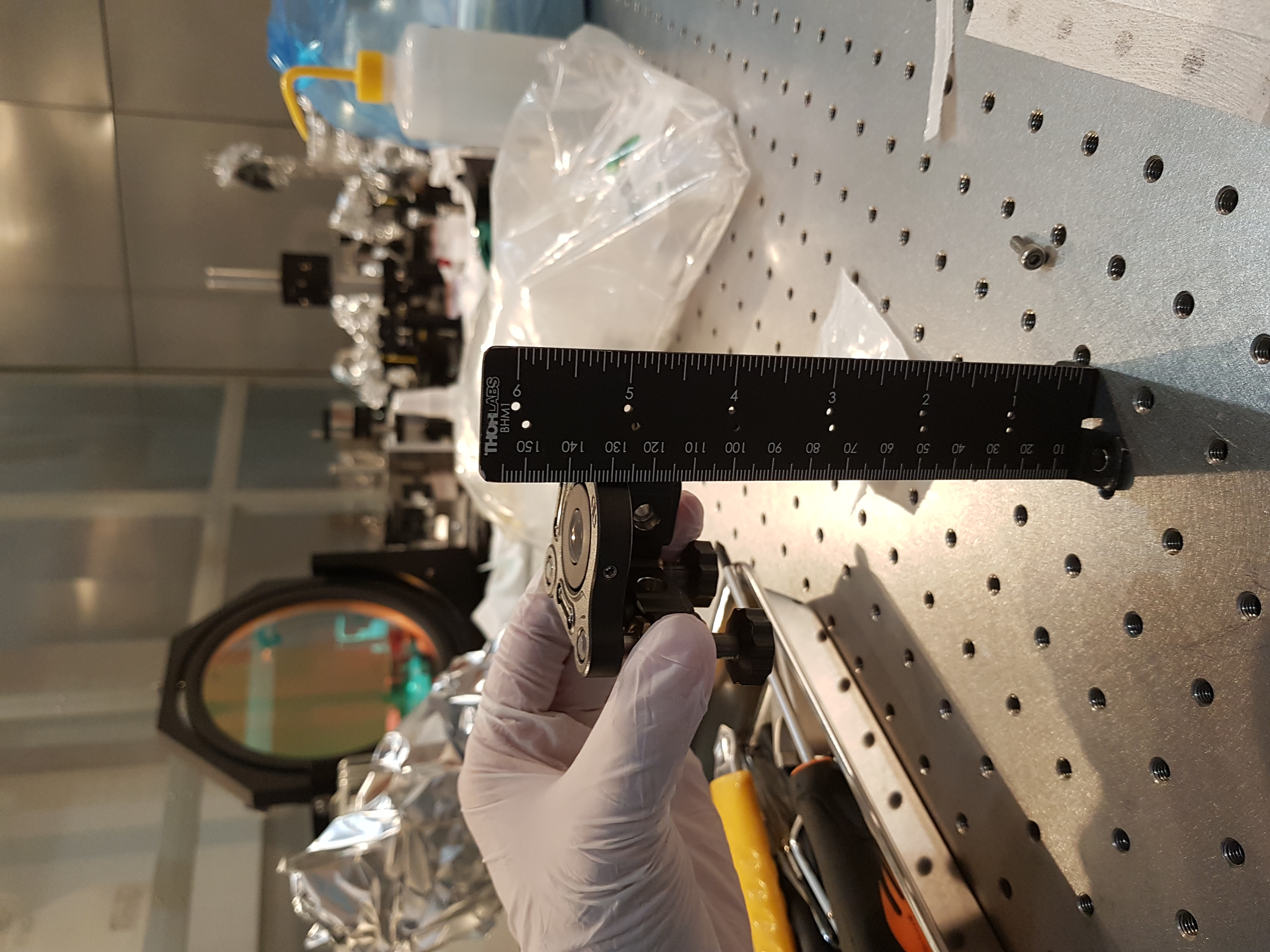
1: Incoupler mirror, looking at focus distance of ceiling light
2: Testing the hot/cold side of the Peltier (blank = hot)
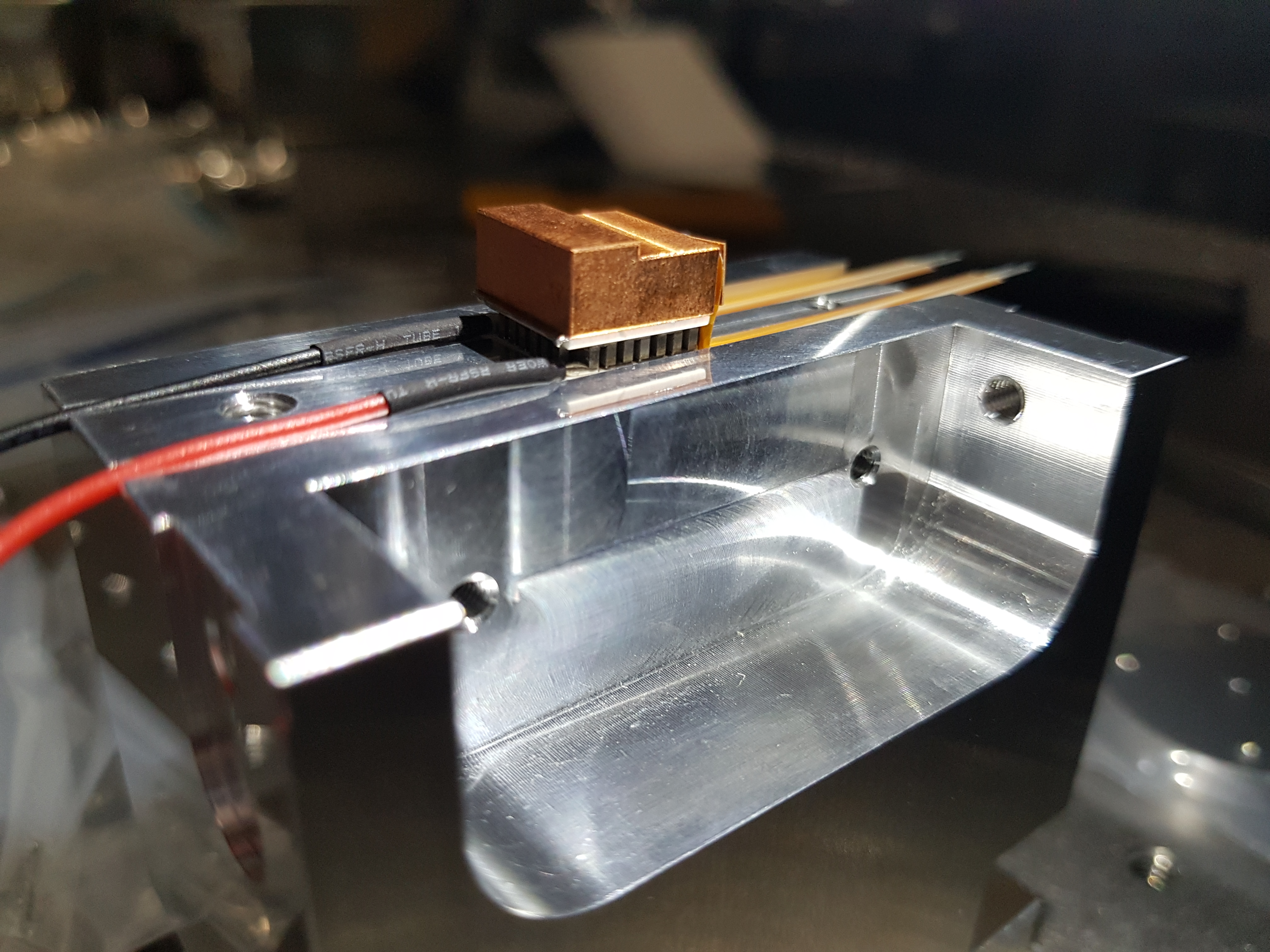
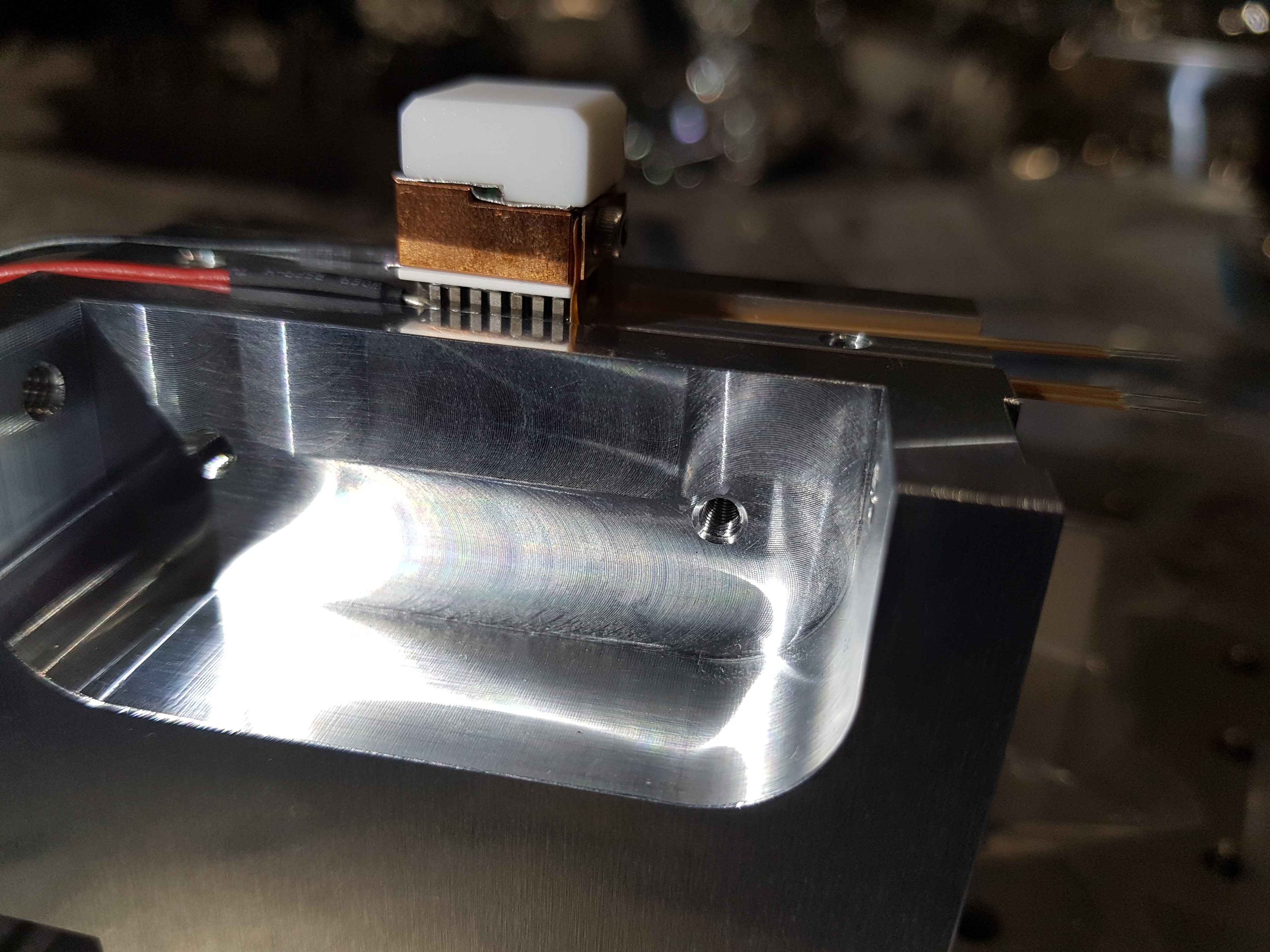
3: Copper L placed on top of Peltier, with 0.1mm indium between the two
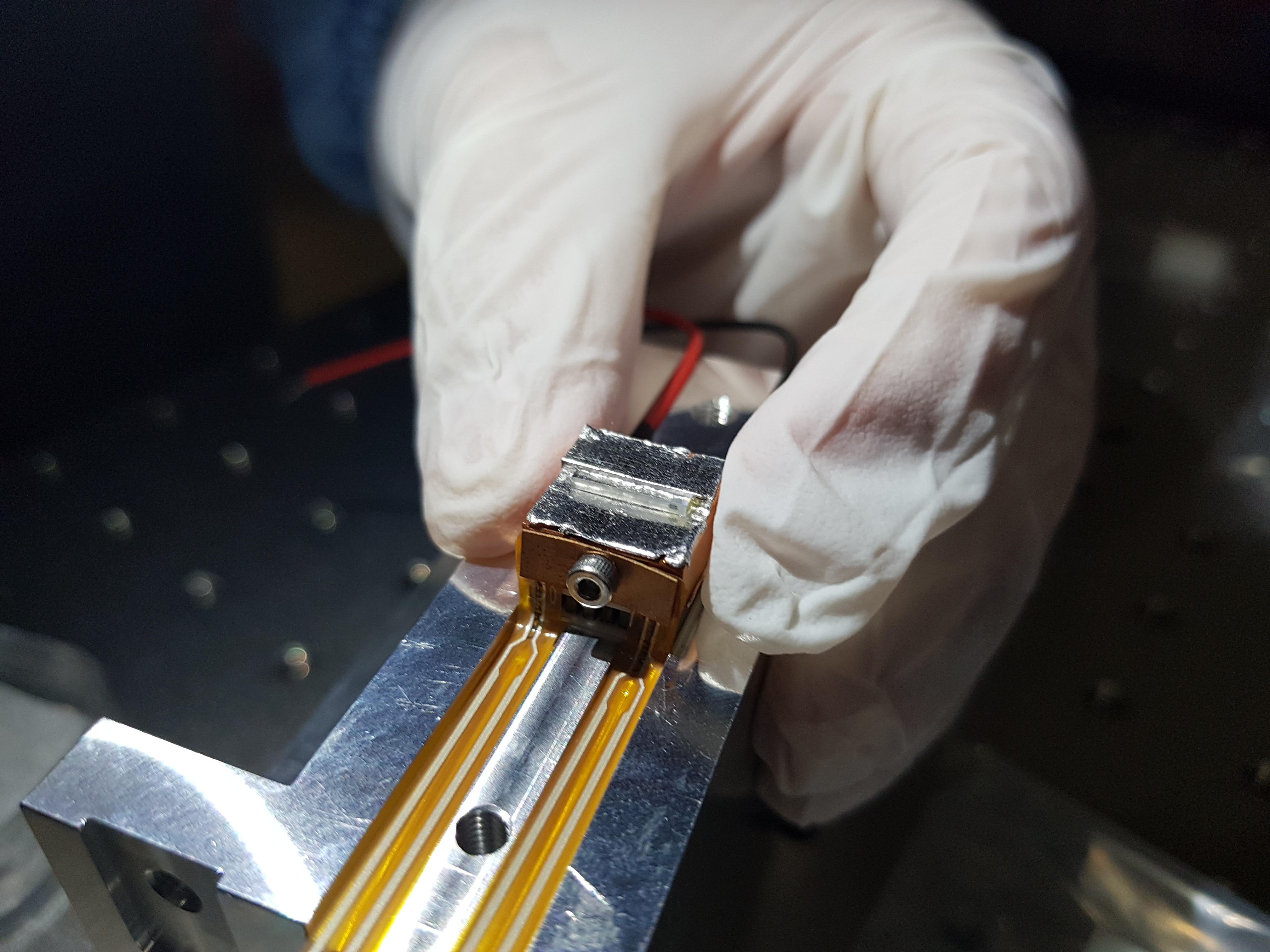
4: Black dot of OPO indicating the HR side
5: Indium not laying flush against the coppler L. We took off the Macor and made sure the indium was properly pressed against the copper
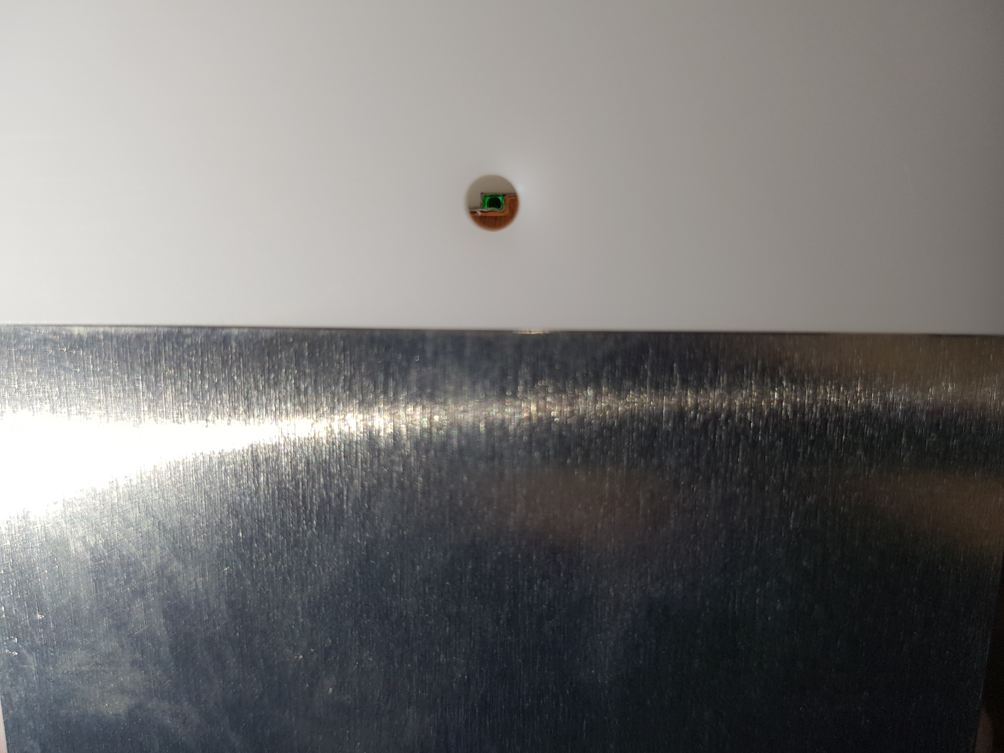
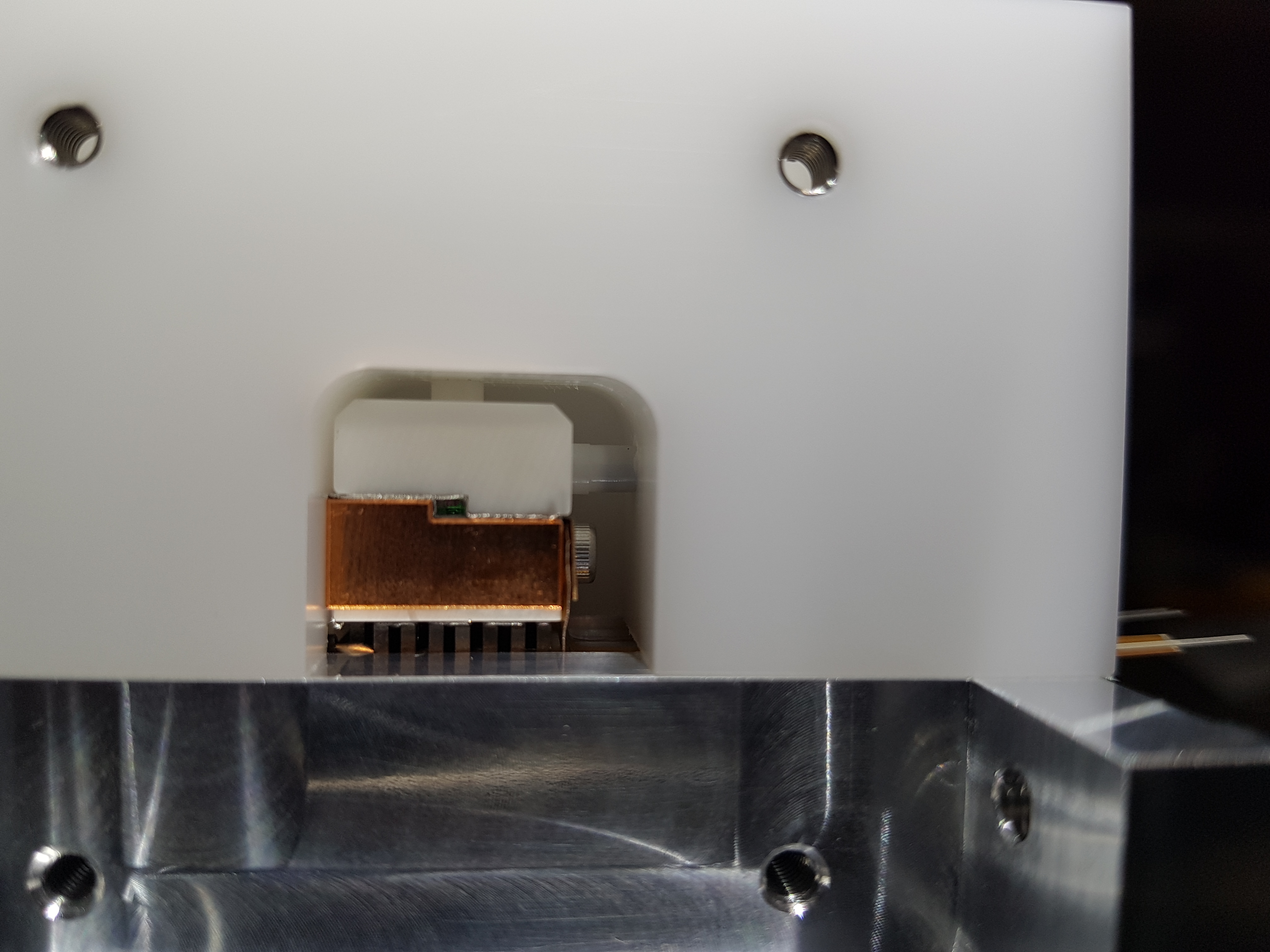
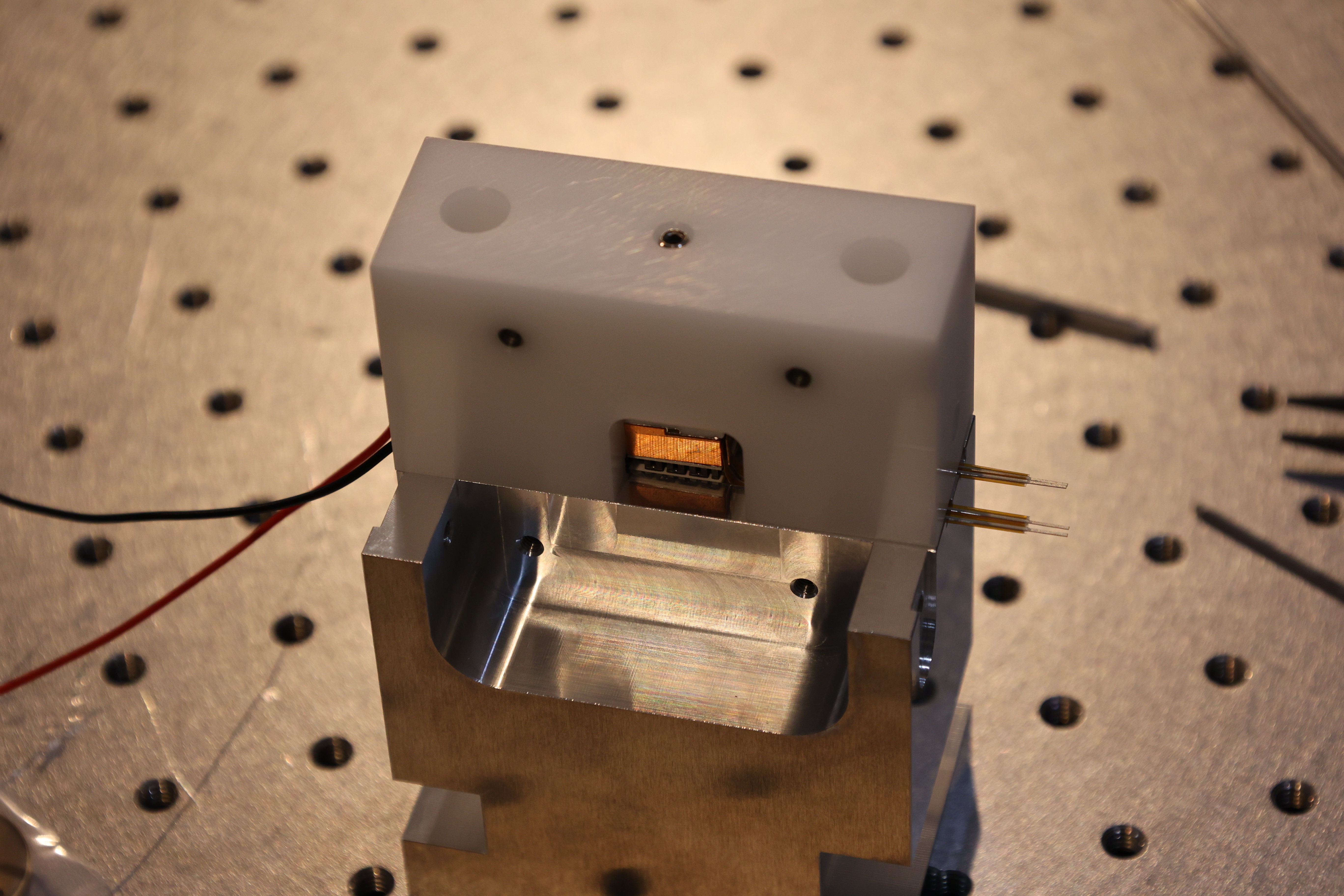
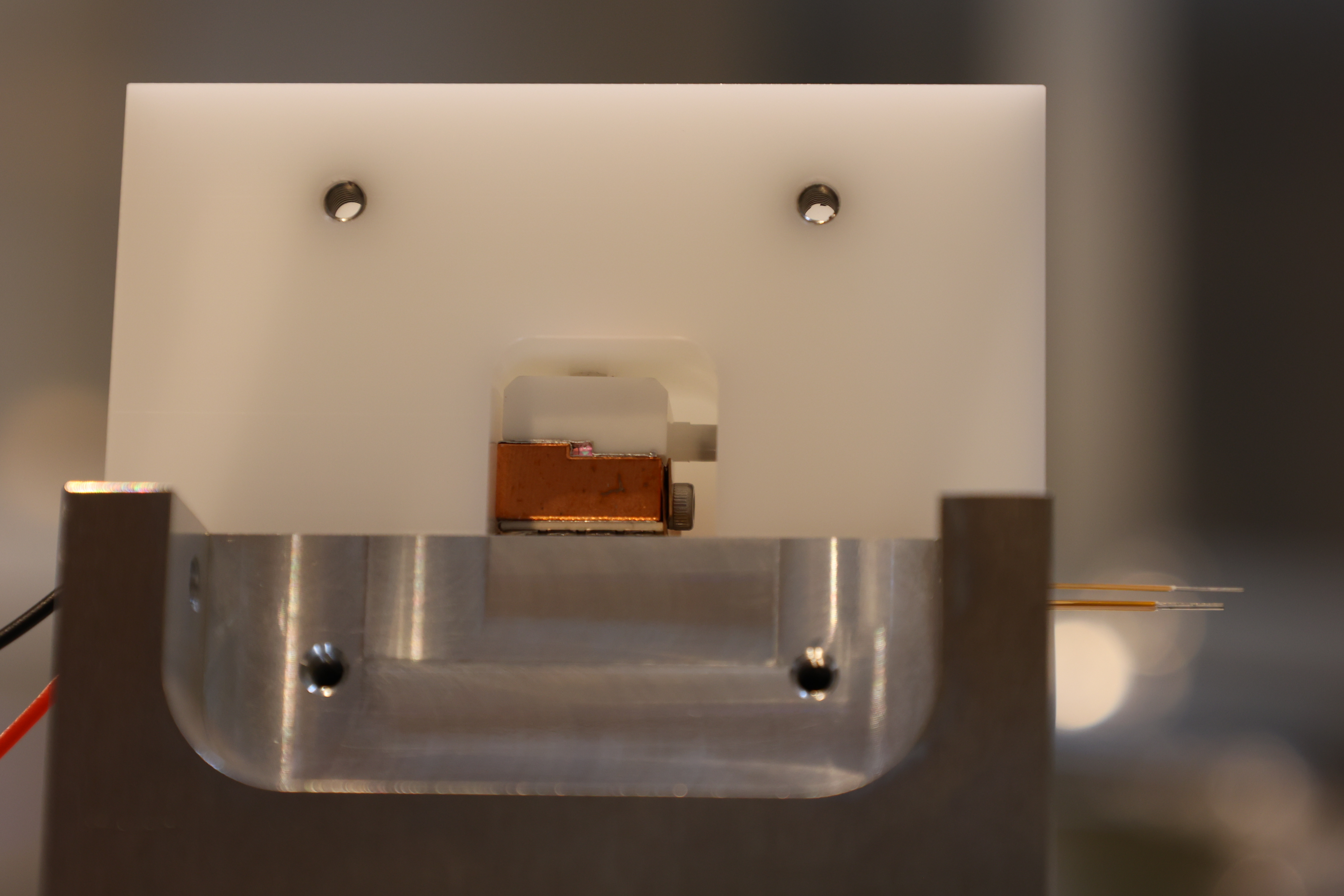
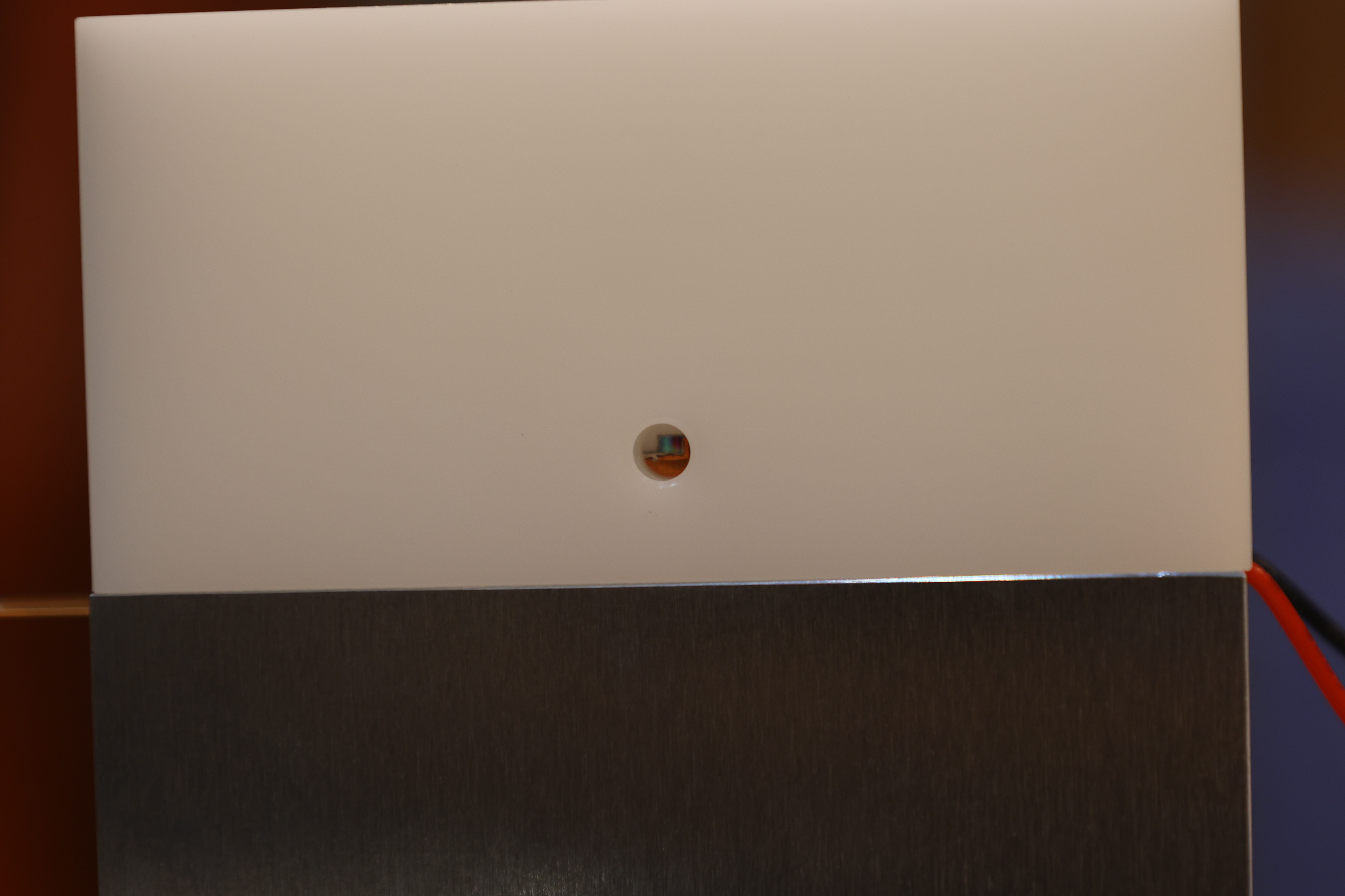
6: Exit hole of the OPO mount. The black dot is closer to this side
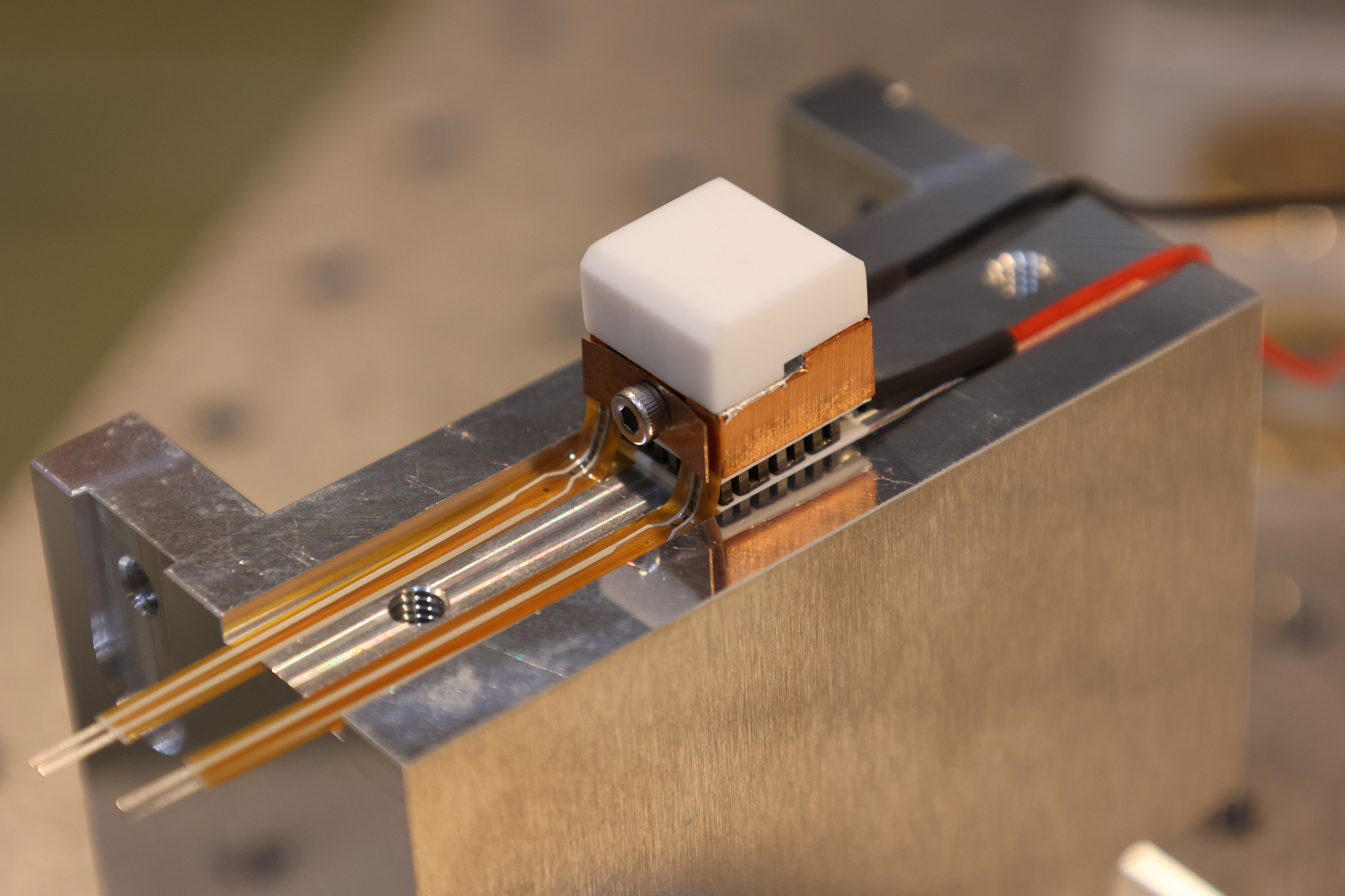
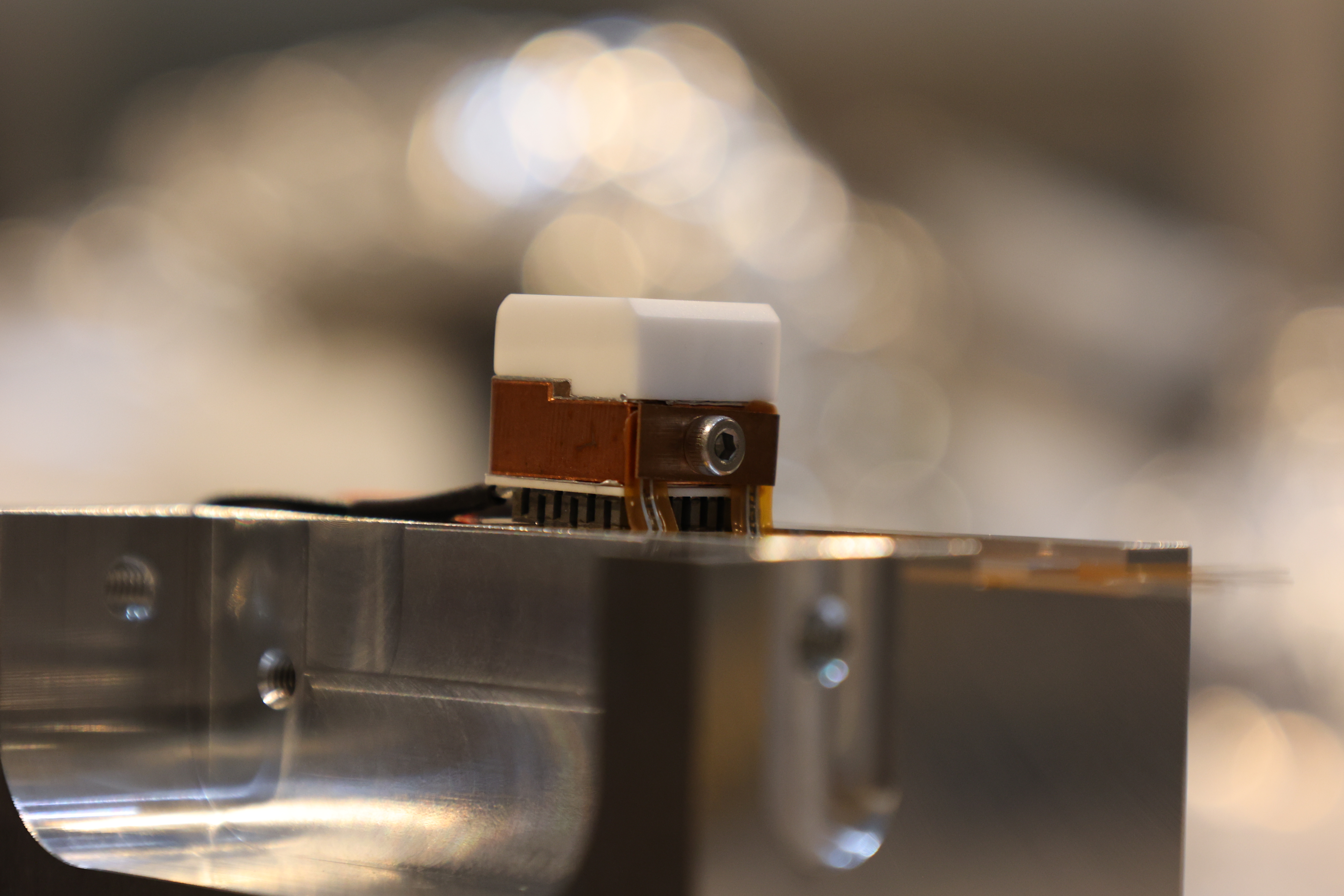
7: Other side of the OPO mount showing the plastic screws holding the Macor/copper L in place
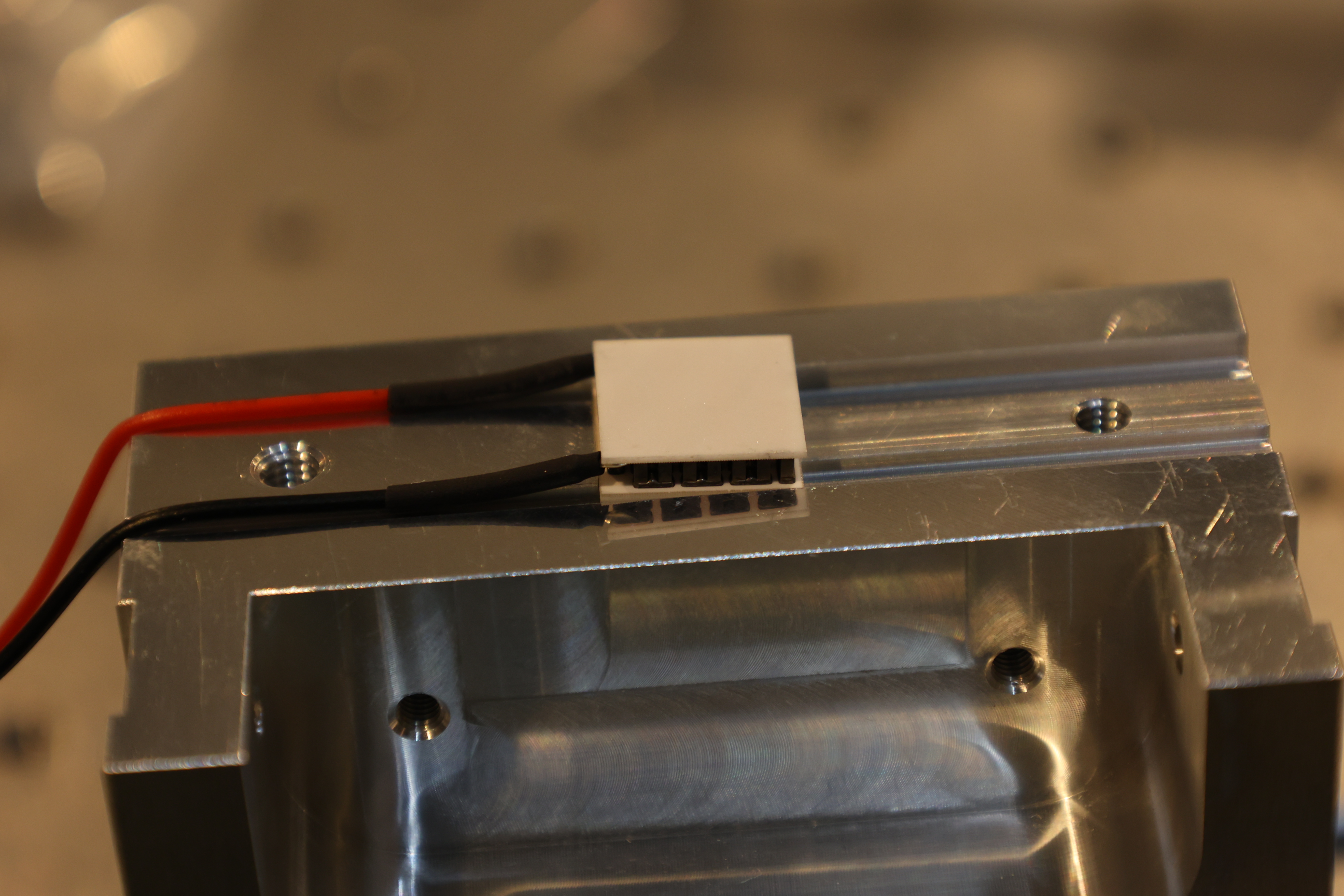
8: Re-assembly of the OPO holder, placing the Peltier the correct way up (note the orientation of the wires)
9: Thermometers connected to the copper L with a mounting plate and screw
10: As above
11: Plastic holder with thermometers and correct Peltier orientation
12: Plastic screws holding the assembly
13: Exit hold of the OPO assembly again