I estimated the level of error signal that we should obtain for locking an OPO cavity. I use similar values as those described in Yuhang/Aritomi's theses for the optical cavity, but will be working with a different modulator. We will lock this cavity using the EOM and then switch off the beam using the AOM in order to obtain a ring down measurement to characterise the losses of the new OPO.
-------
COMPONENTS:
Faraday Isolator - Thorlabs IO-5-1064-VLP
- Aperture: 5 mm diameter
- Aperture heigh: 38mm
- Length: 90 mm
- Max CW power density: 25 W/mm^2 blocking, 100 W/mm^2 transmission
Electro-Optic Modulator - Newport New Focus 4003 Resonant EOM
- Resonant frequency: 40 MHz
- Modulation strength: 0.1-0.3 rad/V
- Aperture: 2mm aperture (ideally 0.4mm beam diameter)
- Aperture height: 14mm
- Length: 56mm
- Max CW power density: 4 W/mm^2
- Max RF power: 1W
Acousto-Optic Modulator - AA Optoelectronic MT110 IR 27 - use manual for MT110-A1.5-xx
- Aperture: ~4mm aperture, should be satisfied by passing through EOM properly
- Aperture height: 8mm
- Length: 22.4 m
- Max rise/fall time: 192 ns
- Max separation angle (0-1): 28.8 mrad
- Max CW power density: 10 W/mm^2
- Bandwidth: 150 MHz bandwidth
- Photocurrent - 0.6 A/W photocurrent at 1064nm
- Transimpedance gain - 5x10^3 V/A for 50 Ohm load, 1x10^4 V/A for high impedance load
- Noise - 2 mVrms nominal
- Detector size - 0.5 mm diameter
--------
SPECIFICATIONS OF OPO CAVITY:
- Input mirror: OPO curved surface, R = 0.99975
- End mirror: Meniscus, R = 0.92
- Length of cavity: 38mm
- Beam waist in OPO cavity: 20.66 µm
- Finesse: 75
- FWHM: 52.5 MHz
- FSR: 3.9 GHz
- No Gaussian beam parameters specified in Finesse modelling
--------
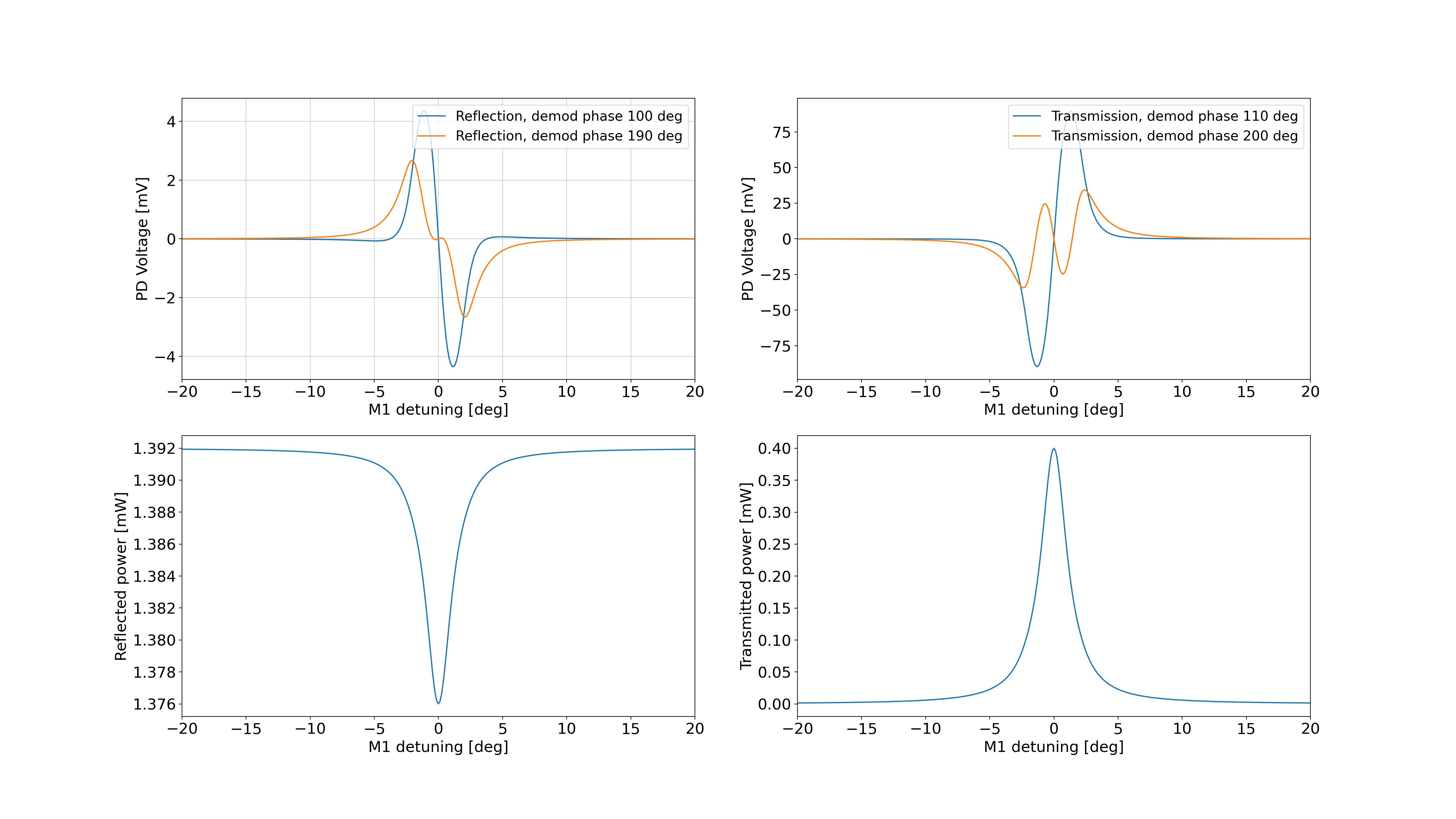
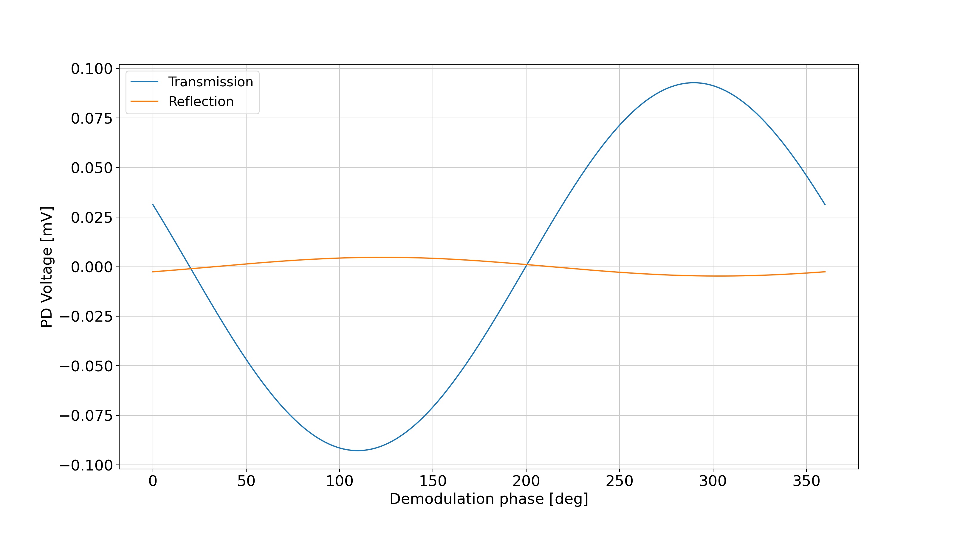
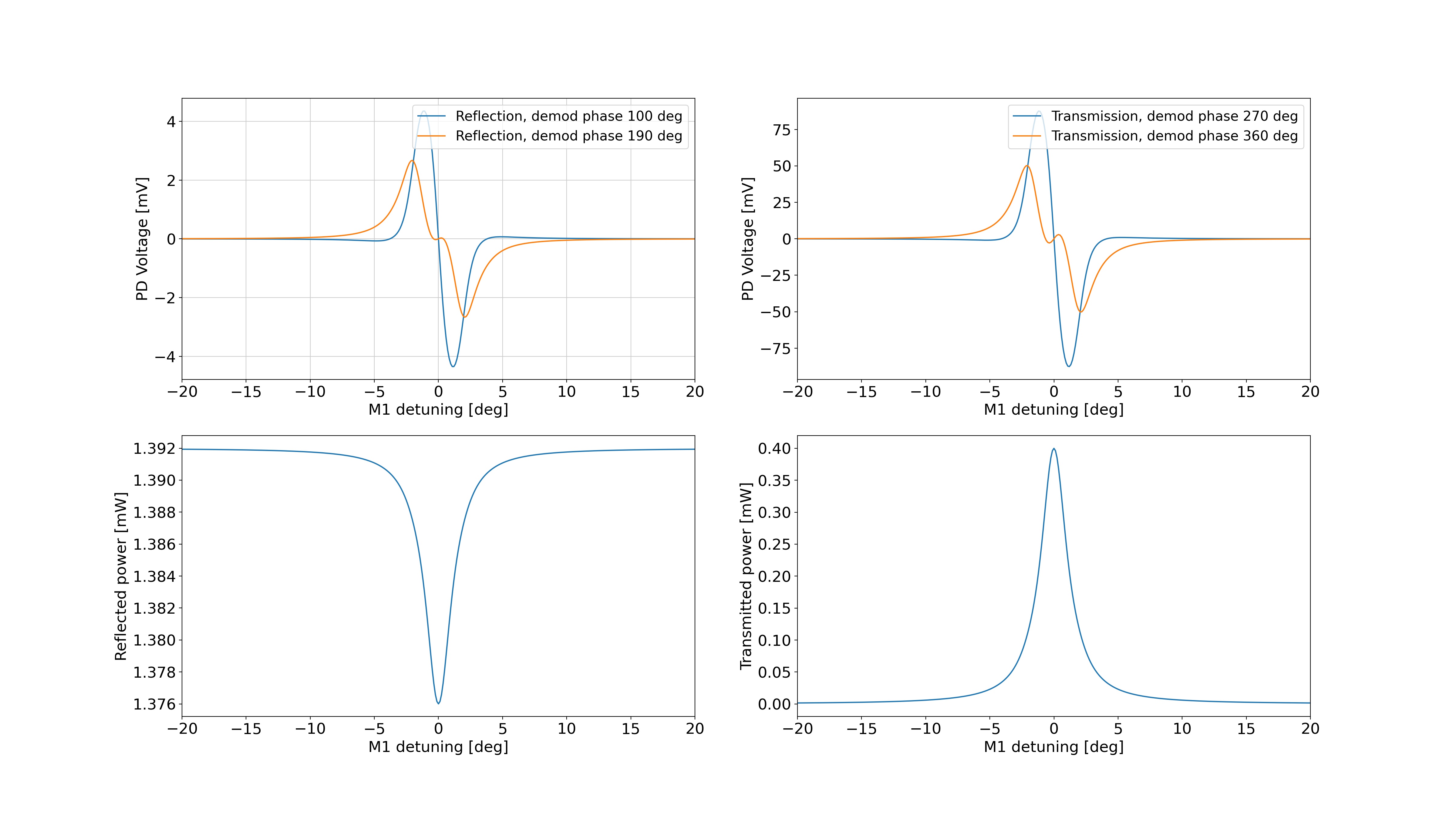
Given a laser input power of approximately 4 mW, I estimate that we will have an error signal with a peak to peak value of less than 10 mV within the linear range. This is extremely small compared to the noise value of the photodetector, so we should use a high power. Figure 1 shows the error signals from the reflection and transmission photodetectors, as well as the reflected and transmitted cavity power, using an input power of 40 mW. Each error signal plot shows the signals of I and Q phase which are spearated by 90 degrees. Figure 2 shows the optimisation of demodulation phase for the particular EOM settings (40 MHz, mod depth 0.3). Figure 3 shows the error signals again but with a different transmission demodulation phase. Perhaps it is better to have the Q phase part be flatter when the I phase is in the linear range.
Looking in the ELog, Eleonora seemed to have the low power issue in 997. This was later fixed by adjusting the mode matching telescope to increase the amount of p-pol into the OPO. Yuhang in 1010 found a simulated error signal reaching 120mVpk and 0.6 mW in transmission of the cavity, for an EOM at 87.6 MHz.
I am not entirely sure of the PPKTP damage threshold but Marc told me it may be an issue. For the modulation optics, the maximum intensity at 40 mW is 0.57 W/mm^2 at the waist. Inside the OPO cavity, the circulating power is ~5 mW with an intensity of 3.7 kW/mm^2.
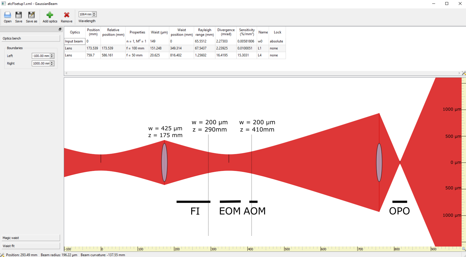
I have also estimated the following lens setup, given that we want a beam at most 0.67 µm diameter through the EOM (after the FI), and 40 µm on the OPO. For the isolator and modulators, the beam should be less than 1 mm diameter for a range of more than 20 cm, and less than 0.4mm diameter when travelling through the 56mm EOM. The lens setup is shown in Figure 4 with approximate indications of the FI, EOM and AOM lengths.