Yuhang and Michael
We refer to the previous logbook entries:
1904 - Reference measurement to IRPS jitter noise
2393 - First entry on this topic describing the new layout of the phase shifter to orient in perpendicular incidence and jitter noise
2407 - Previous entry on IRPS replacement, with measurement of X and Y channels of PSD
This time, we performed a series of measurements of the X and Y channels on the PSD, divided by the T (total) channel (i.e. frequency response 2/1 in spectrum analyser). This was motivated by the entries 1904 and 2407, where after discussion we determined it was ambiguous whether or not we were measuring jitter or amplitude noise - since we were measuring past the IRMC, we are taking the transmission of the mode cleaner, the power output of which is affected by the alignment of the input beam. This also motivated Yuhang to simulate the effect of beam waist positioning on the noise at the PSD past the IRMC.
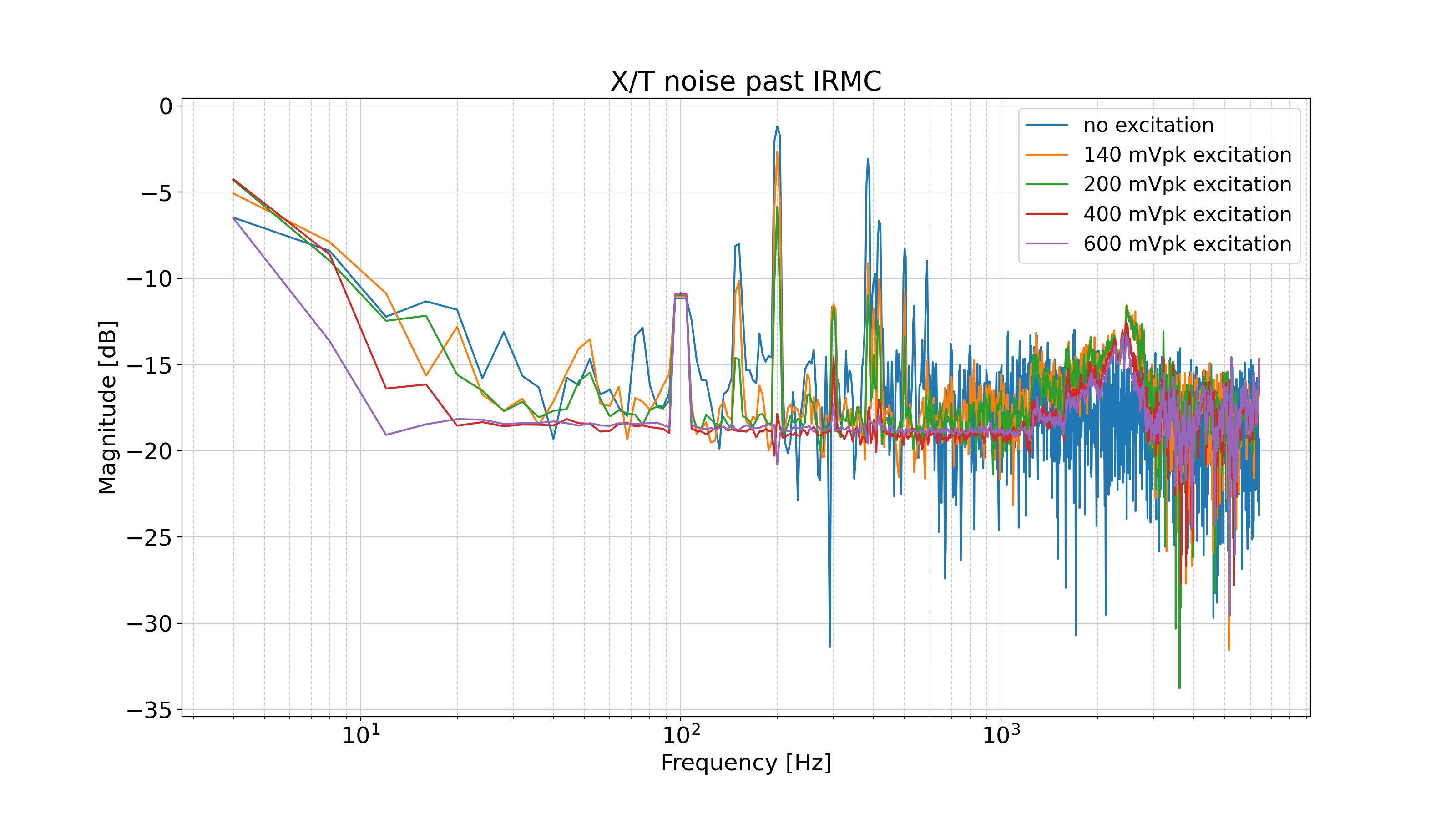
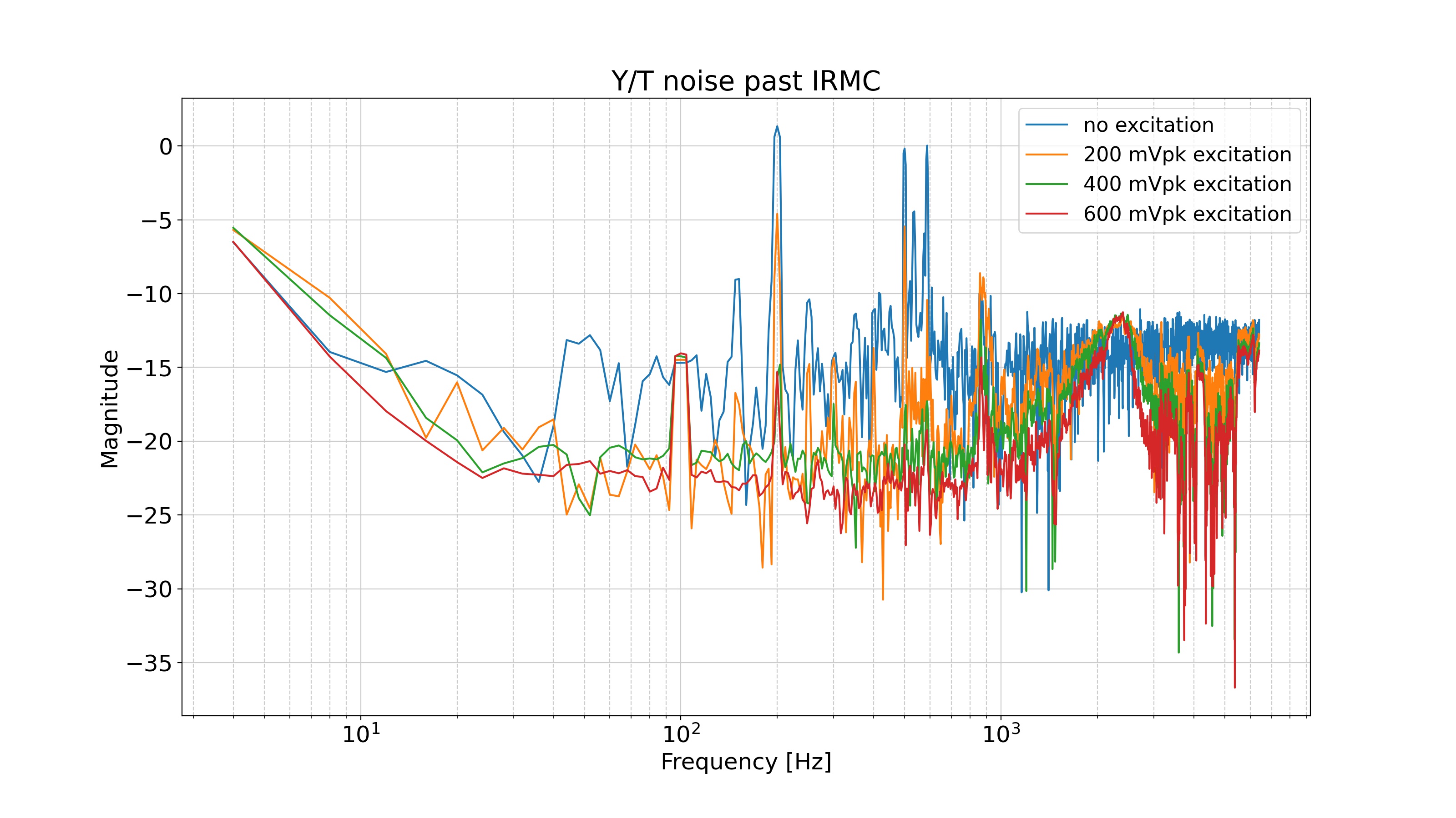
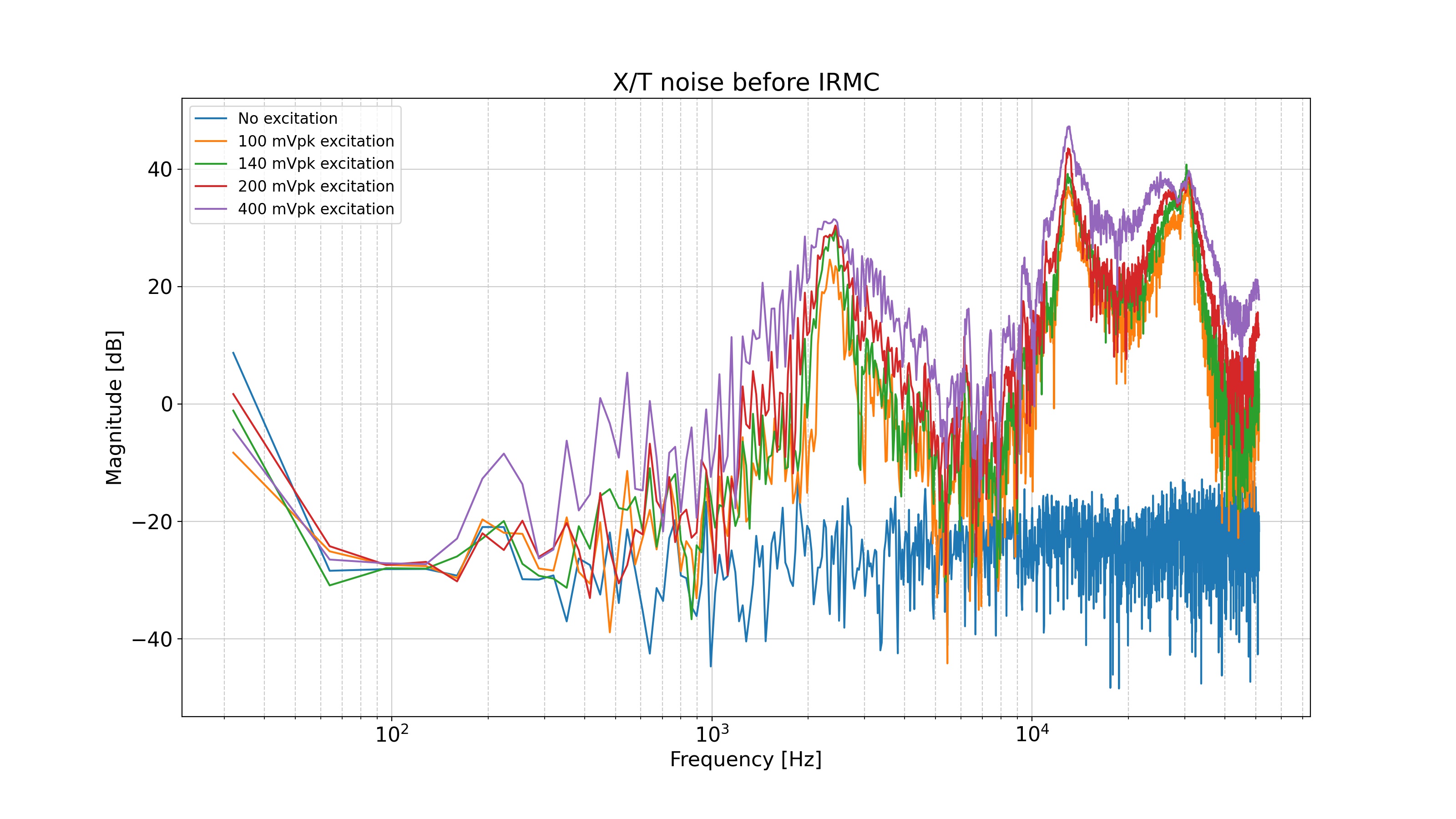
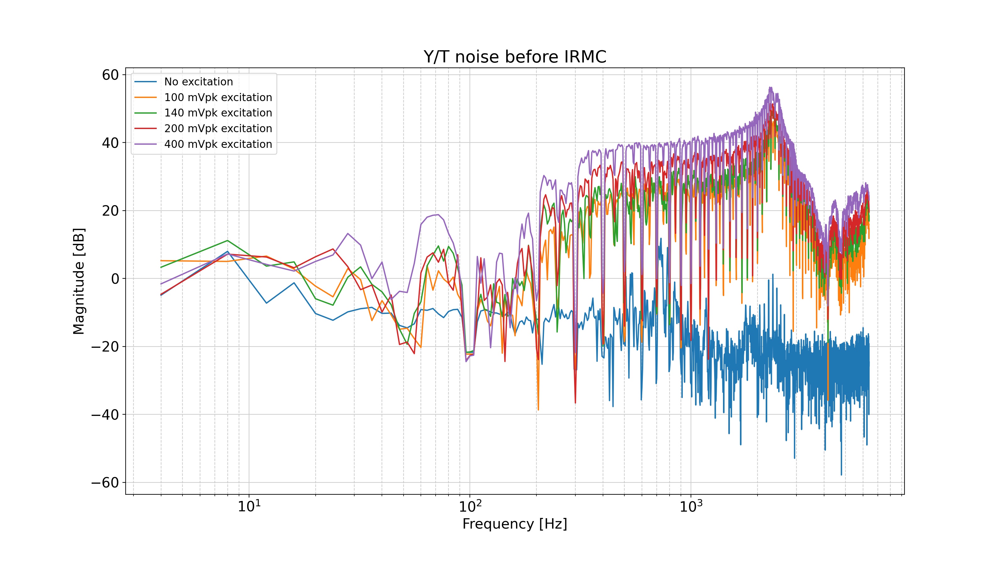
First, we took the measurements of X/T and Y/T using a PSD just past the homodyne detector's flipping mirror, shown in figure 1 and 2. In the X/T (Yaw) case, the relative contribution of the X and T channels changes very little with the amount of excitation. The noise floor is similar to no excitation with the difference of a broad peak at about 2.3 kHz, which could correspond to the beam vibration frequency of the PZT element supporting the phase shifter mirror. In the Y/T case (pitch), the contribution of the Y channel actually decreases with respect to T. However, we saw in 2407 that the absolute value of the Y noise is quite high. This indicates that there is quite a lot of amplitude noise introduced on the Y channel. Yuhang's simulation indicates that this amplitude noise may be caused by the phase shifter being offset from the beam waist. The results motivate us to do the following two measurements, prior to adjusting the relative position of waist/phase shifter: 1 - measure the X, Y/T noise induced by the phase shifter excitation, with the PSD before the IRMC, and 2 - measure the spectrum of the IRMC when changing the voltage sent from its high voltage driver, specifically looking at the behaviour of higher order modes as the IRMC is mismatched.
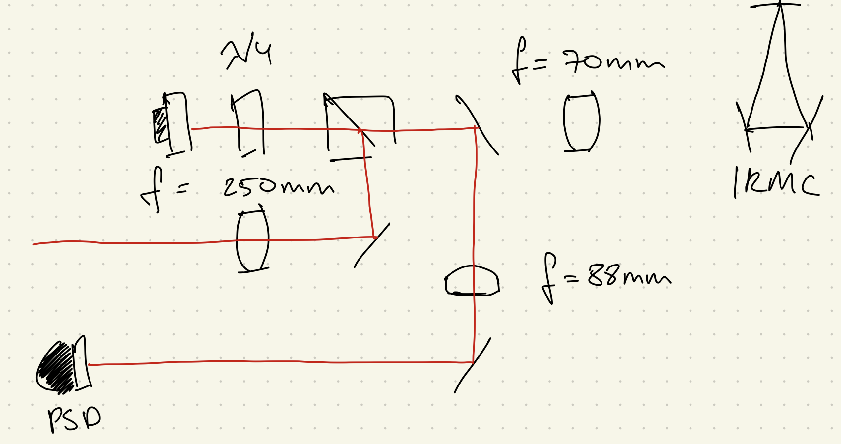
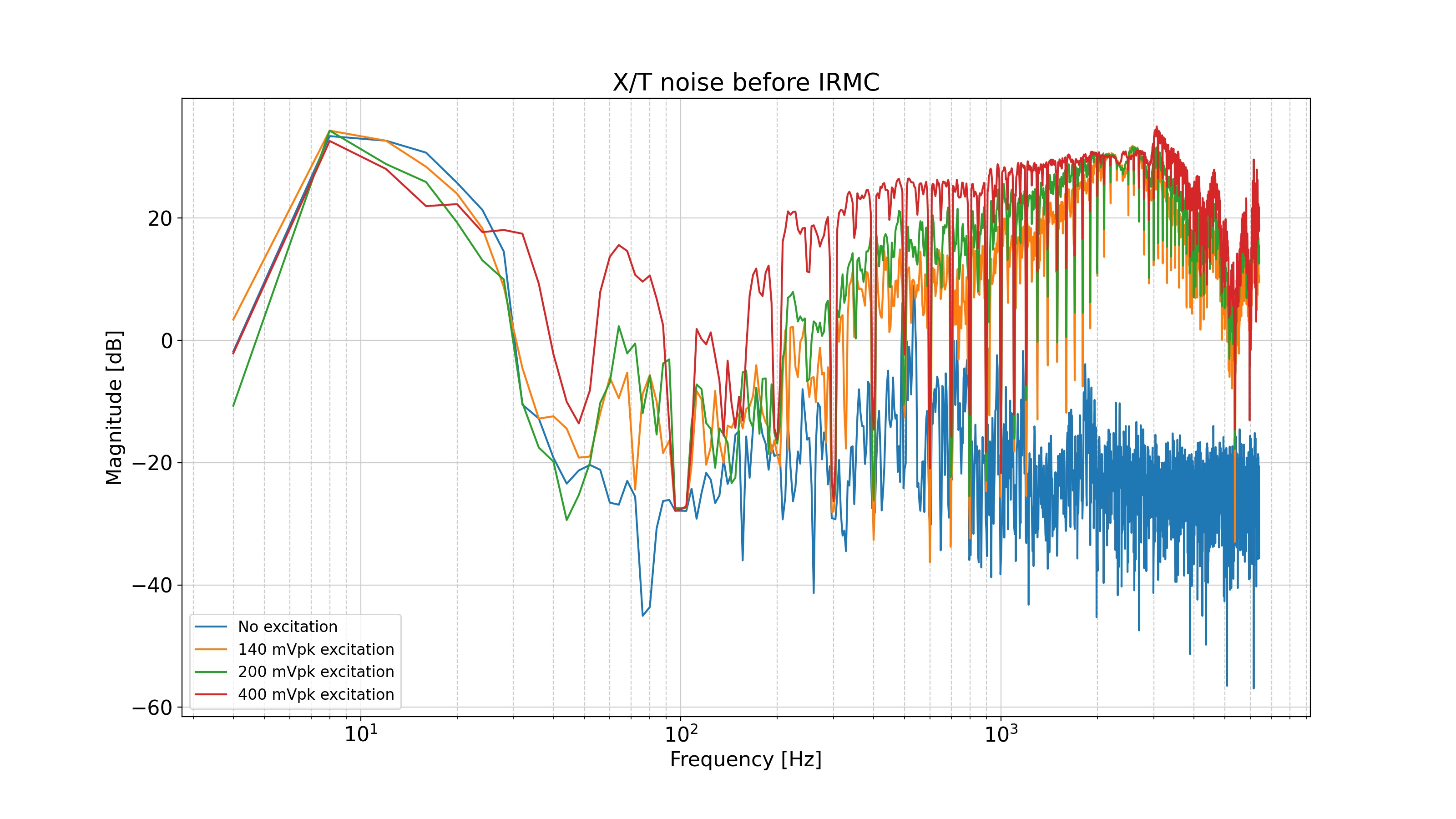
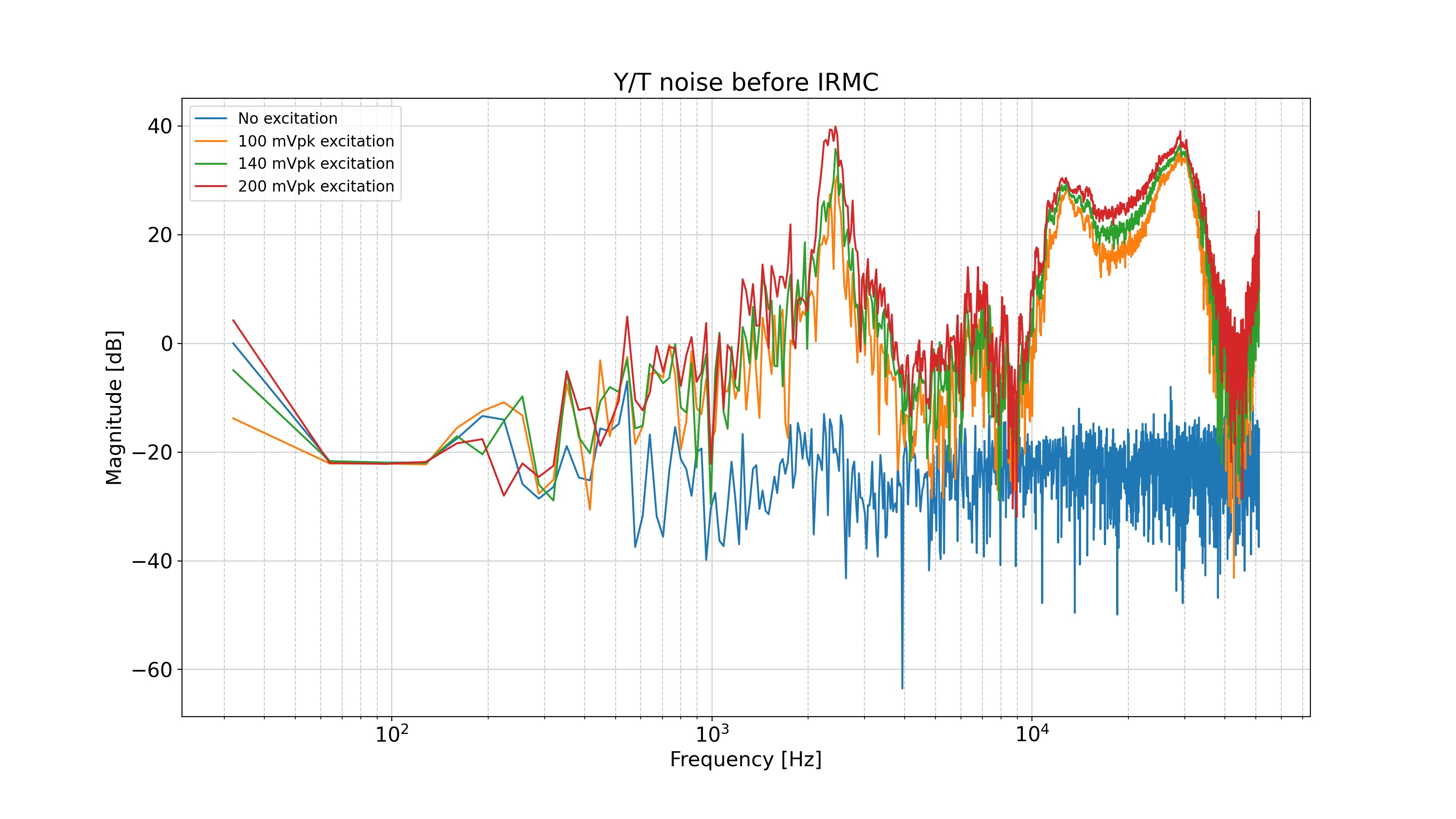
So far, we have taken measurements of the jittering before the IRMC. A sketch is shown in figure 3. Measurements are shown in figures 4-6 (some traces at certain values of excitation are missing due to data corruption) In this layout, we are definitely measuring more angular deflection now. In all cases,the contribution of X and Y increases relative to T with increased phase shifter excitation, and is also higher in relative magnitude, often above 0 dB. By contrast, the X, Y/T do not go above 0 dB after the IRMC. This increased noise may also be due to some other broad resonances at about 12 kHz and 30 kHz.