Marc, Michael and Yuhang
We were guessing that back scattered noise is not from suspended mirror motion in elog2366. To further understand where the low frequency noise comes from, we did more checks. I think the understandling is much more clear now.
From the check we did in last few days, in conclusion, the low frequency noise has two components: back scattered noise from lens inside homodyne, local oscillator amplitude noise (or lo jittering).
In detail:
Last week, we tilted the lenses inside homodyne as what I did together with Eleonora. We found low frequency noise was reduced inside squeezing spectrum. But there were still residual noise. To understand where the residual noise from, we checked many noise spectrums and we found the IRMC reflection has some peaks very similar with some peaks inside squeezing spectrum. Besides, we also tried again to cover homodyne better from potential scattered light, which didn't improve the situation. Since the IRMC reflection indicates the amplitude noise of local oscillator, we start to suspect this amplitude noise to be the reason of part of low frequency noise inside squeezing spectrum.
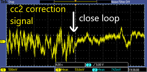
The local oscillator amplitude noise (jittering) has been preliminarily investigated together with Yaochin (elog 1904). We found it to come from the large correction signal sent to CC2 phase shifter. Besides, we have tried to offload this correction by sending part of this signal to filter cavity input mirror. However, it was not successful at that time. To improve this situation, I had a look of the filter design for filter cavity AC local control. Especially, I investigated the fitlers designed by Eleonora and Ettore. I copied this filter, modified it, and used it for feeding back CC2 correction signal to filter cavity input mirror. In the end, we could offload quite a lot of correction signal sent to CC2 phase shifter. Attached figure 1 shows the difference of CC2 correction signal when the loop (CC2 correction send to filter cavity input mirror) engaged.
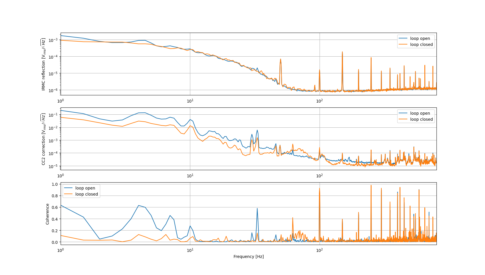
After that, we compared again the CC2 correction signal and IRMC reflection with and without this control loop (CC2 correction send to filter cavity input mirror). Attached figure 2 shows their spectrums and coherence. We found the IRMC reflection has smaller peaks at low frequency (smaller than 10Hz). But there were not much difference above 10Hz. Besides, It is diffcult to tell if the amplitude noise is reduced or not in this measurement because IRMC reflection should be mostly limited by shot noise. We can also notice an increase of coherence between 60 and 80Hz. This proves the effect of control loop for local oscillator amplitude noise at high frequency (tens of Hz).
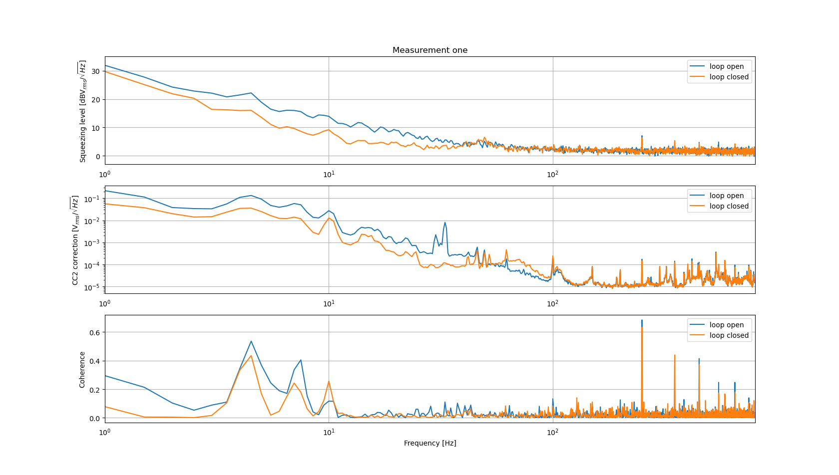
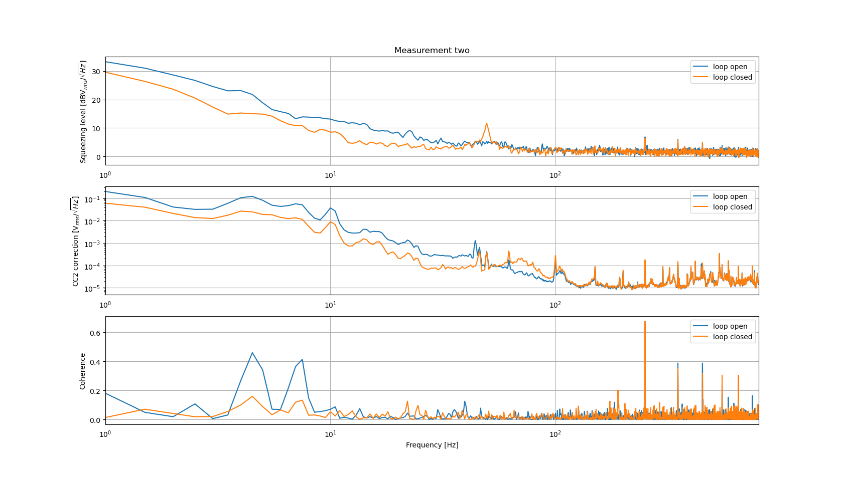
Most importantly, we checked twice the squeezing spectrum and CC2 correction signal with and without this control loop (CC2 correction send to filter cavity input mirror). Attached figure 3 and 4 shows the two measurements of their spectrums and coherence. In the squeezing spectrum, a clear decrease of low frequency noise is visible when the loop is engaged. The decrease of squeezing low frequency noise is very similar with the decrease of cc2 correction signal. So we suppose, in this configuration, the local oscillator amplitude noise is dominating. There are still test to be done to validate this guess. But I made a simulation of this back scattered noise (formula from Irene Fiori or many other papers). From this simulation, the reduction of total motion will just make the whole shoulder of back scattered noise move to lower frequency. At the same time, the low frequency shoulder height should be kept the same level. (see figure 5) And this is not the case of our measurement. So we could also conclude, in the current experimental configuration, low frequency noise behaves more to be local oscillator amplitude noise.
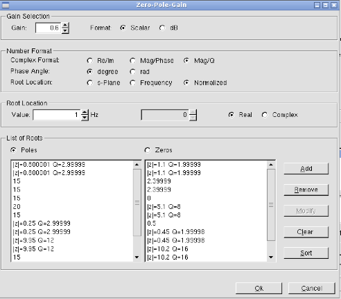
The control filter configuration is in figure 6 and 7. Note that we could see from the spectrum of CC2 correction signal that, the unity gain frequency should be around 50Hz. We are introducing an obvious peak around UGF. So the filters still have room to be improved.