[Aritomi, Yuhang]
This is work on Aug 17th.
First we maximized WFS2 I3 12Hz INPUT PIT by DDS demodulation phase. We set WFS2 segment 3 DGS phase 0. The optimal DDS demodulation phase for WFS2 I3 was 160 deg.
Then we optimized other WFS2 segments by DGS demodulation phase. We found that optimal demodulation phases for other WFS2 segments were around 40deg. This is quite different from WFS2 segment 3 demodulation phase which is 0 deg. Maybe this is related to broken WFS2 Q3 channel and it will be solved by fixing the channel.
We also optimized WFS1 segments by DGS phase. The optimal DGS demodulation phases for WFS1 were around 0 deg. Here is a summary of optimal DGS demodulation phases with 160deg of DDS demodulation phase.
| segment | WFS1 1 | WFS1 2 | WFS1 3 | WFS1 4 | WFS2 1 | WFS2 2 | WFS3 3 | WFS3 4 |
| optimal DGS phase | 0 | 10 | 0 | 0 | 40 | 35 | 0 | 40 |
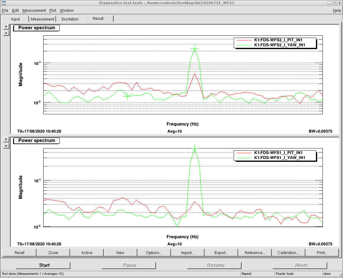
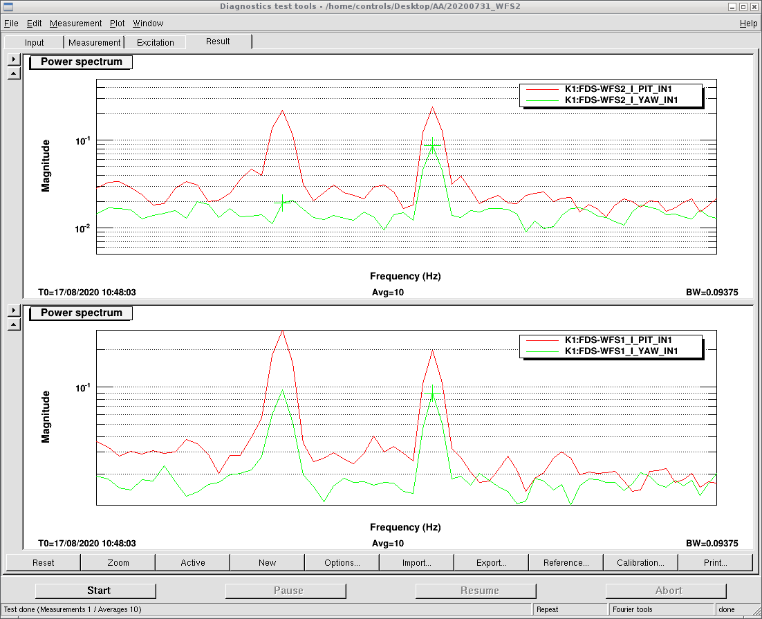
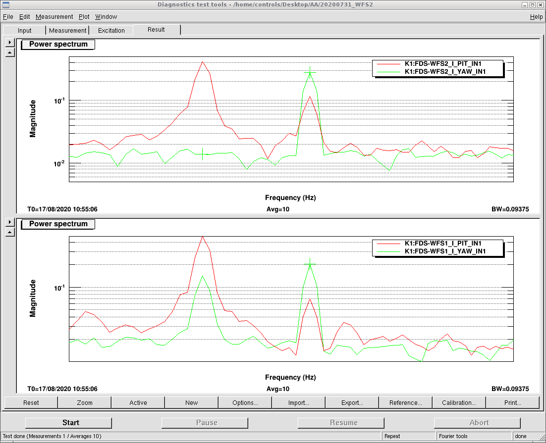
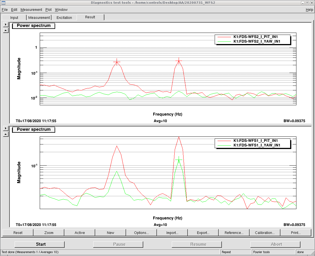
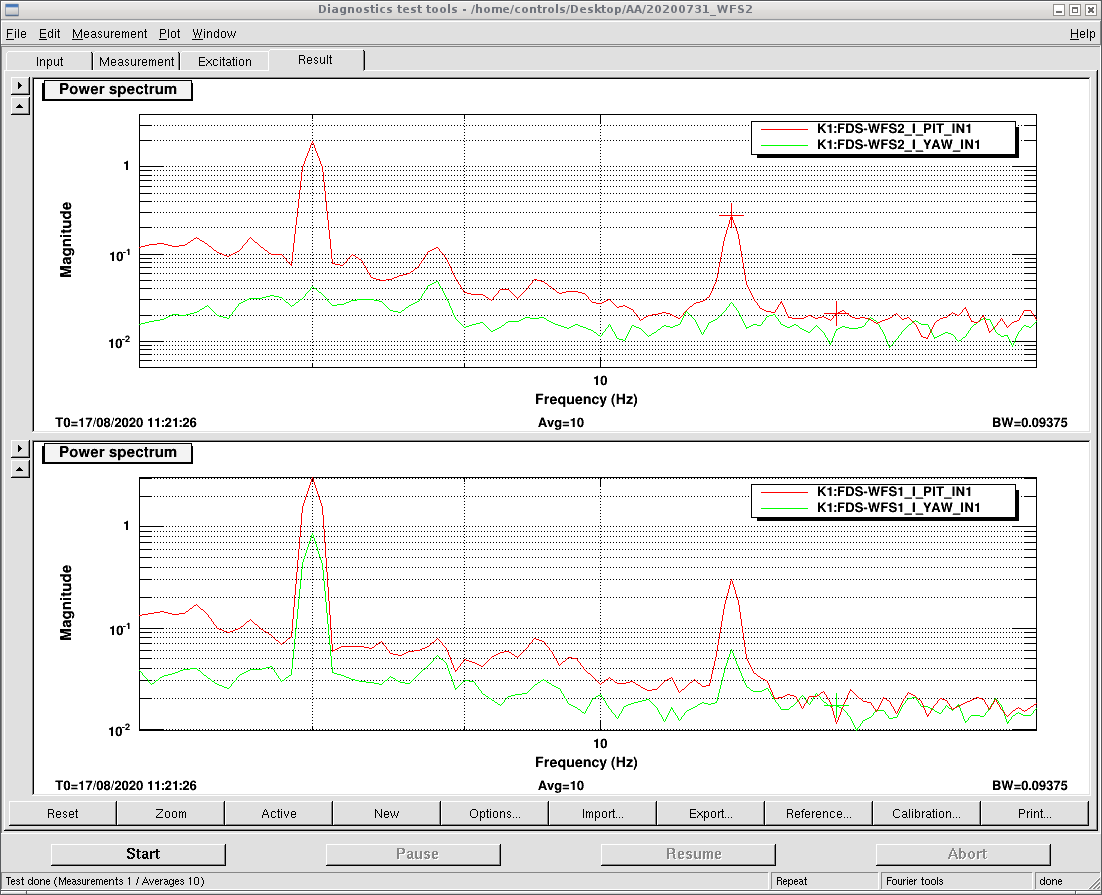
We measured sensing matrix. We still have pitch and yaw coupling...
(Pic. 1-4: INPUT PIT, INPUT YAW, END PIT, END YAW)
| INPUT PIT | INPUT YAW | END PIT | END YAW | |
| WFS1 I PIT | 0.4 | 0.03 | 0.2 | 0.07 |
| WFS1 I YAW | 0.03 | 0.49 | 0.09 | 0.2 |
| WFS2 I PIT | 0.26 | 0.05 | 0.24 | 0.12 |
| WFS2 I YAW | 0.01 | 0.23 | 0.09 | 0.28 |
After that we found that WFS1 pitch and yaw coupling for INPUT PIT changed in several minutes (Pic. 5)...
We also injected a 8Hz line to INPUT PIT, but WFS1 pitch and yaw coupling is similar with 12Hz line (Pic. 6).