[Aritomi, Yuhang]
We measured sensing matrix of WFS1. We injected a line to pitch and yaw of input mirror. The frequency of the injected line was 12 Hz and the amplitude was 2000. Then we measured WFS1_PIT and WFS1_YAW signal.
First we injected a line to pitch of input mirror and measured 12 Hz peak of WFS1_I_PIT and WFS1_I_YAW with demodulation phase R = 90 deg. With R = 90 deg, WFS1_I and WFS1_Q signals were almost the same. The measured 12 Hz peak is as follows.
| WFS1_I_PIT | 0.25 |
| WFS1_I_YAW | 0.038 |
This means we have about 10% coupling from pitch to yaw of input mirror. This may be due to coupling of coil-magnet actuator driving.
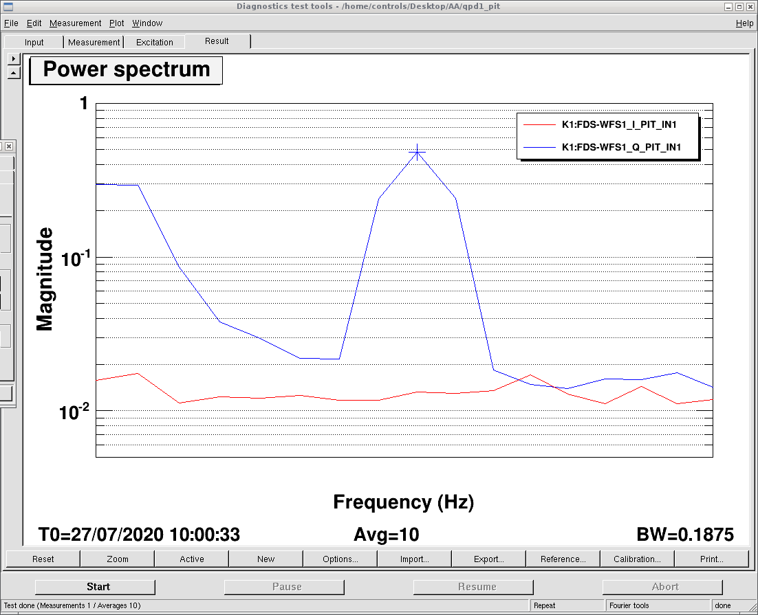
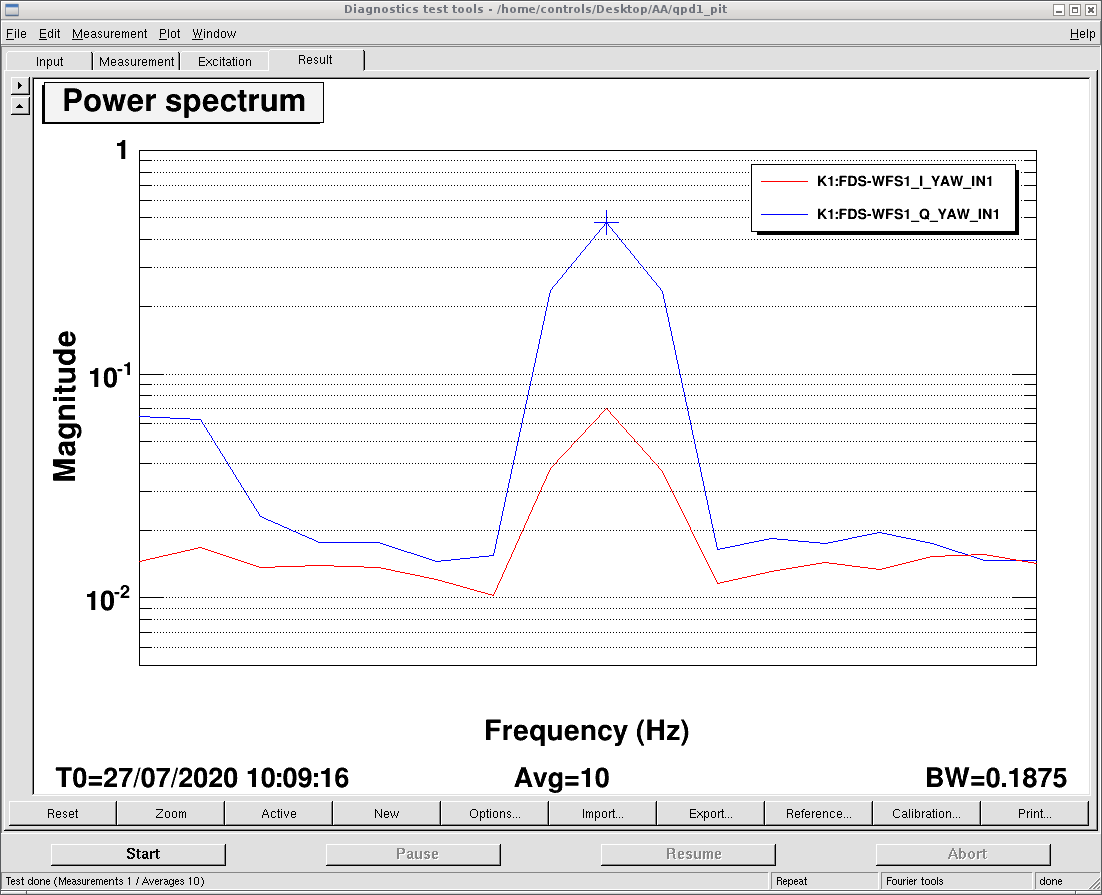
Then we optimized the demodulation phase R in order to maximize WFS1_Q_PIT signal. The optimal demodulation phase for WFS1_Q_PIT was R = 20 deg. After that we injected the same line to yaw of input mirror and measured WFS1_I_YAW and WFS1_Q_YAW. Measured sensing matrix of WFS1 for pitch and yaw with demodulation phase R = 20 deg is as follows. Screenshots of the 12 Hz peak for PIT and YAW are also attached.
| I phase | Q phase | |
| WFS1_PIT | 0 | 0.48 |
| WFS1_YAW | 0.07 | 0.47 |
The optimal demodulation phase R = 20 deg for pitch was not exactly optimal for yaw, but it seems we can use WFS1 Q phase signal for both pitch and yaw.
We'll replace galvo servo for QPD2 and measure sensing matrix of WFS2.