Shimode-san, Miyakawa-san
After experiencing the failure of AA channels and PSD reported in entry #2096. We shipped the PSD and its power supply to Kamioka where Shimode-san investigated the circuits.
His report is reported below (the japanese version is in the attachments):
1. Features of 100V of NAOJ power supply
3pin Earth terminal: Earth line connected to cold and grounded into earth through the power distribution. (Pic 6. "100v_Earth.jpg")
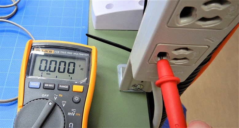
3pin Cold terminal: Power output connected to Earth on the power distribution. (Pic 5. "100v_Cold.jpg")
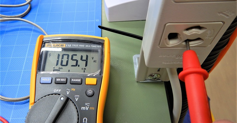
3pin Hot terminal: Power output not connected to Earth on the power distribution. (Pic 7."100v_Hot.jpg")
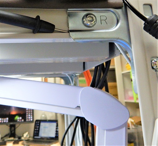
* Note that the tester voltage is based on the Earth (rack) of the building. (pic 3. Earth_point.jpg)
2. Features of connection between PSD and power supply
(1) The PSD chassis is connected to the power supply chassis by a shield on the power connection cable. As a result, the PSD chassis and the power supply chassis have the same voltage.
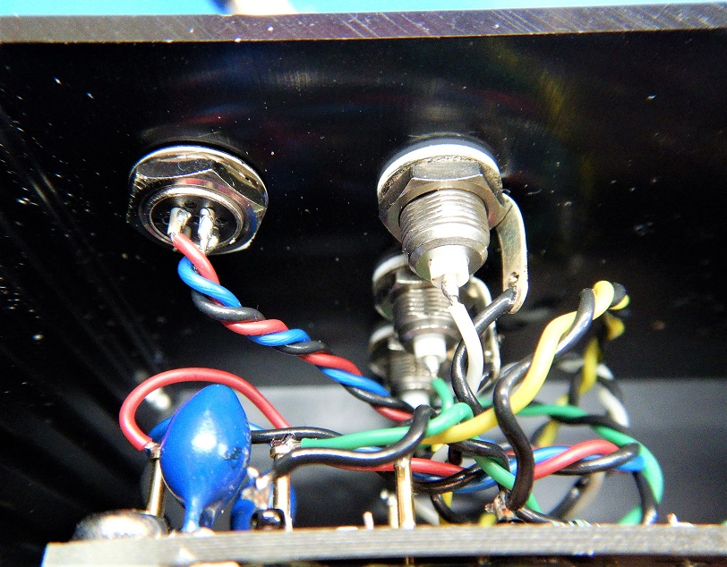
(2) The NAOJ power supply's GND (black) is isolated from the power supply chassis. Therefore, the PSD chassis and the PSD board are at different voltage levels from the PSD's GND.
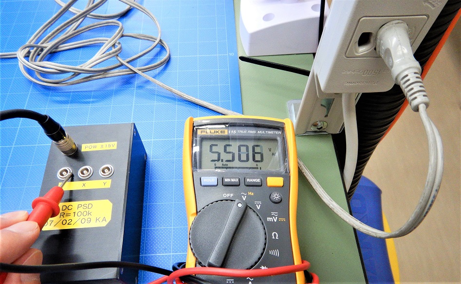
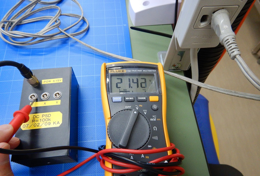
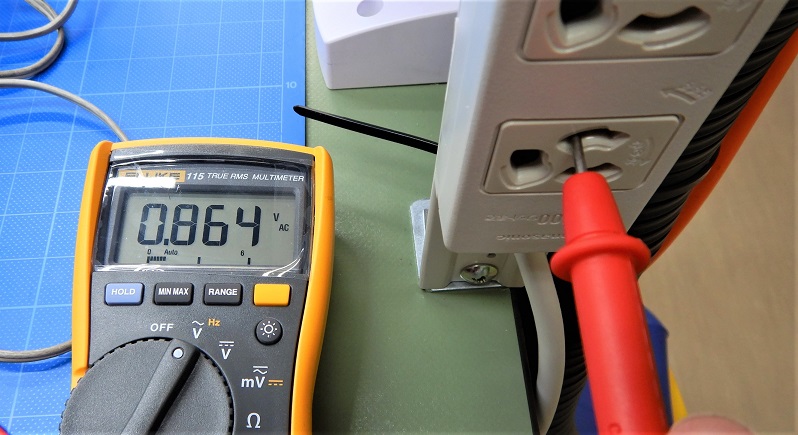
(3) The voltage difference between the NAOJ power supply's GND and the 3pin 100V power supply's ground terminal is about 21V! or 1V depending on the way to plug to AC100V power (forward and reverse). (pic.1, pic.2 "100vON_A.jpg" "100vON_B.jpg)
3. GND in each chassis.
(1) About PSD output
As shown in "PSD_connector.jpg", the outer of LEMO is GND because of the unbalanced output. If conversion to BNC without connecting to chassis GND, the voltage at "2. (3)" is applied to both positive and negative.
(2) BNC to Dsub chassis
BNC is from parallel input to Dsub parallel output. GND is not connected in the chassis. (See https://gwdoc.icrr.u-tokyo.ac.jp/DocDB/ 0047/D1604782/001/BncDsub_ADC.pdf )
(3) About AA/AI Chassis
The 5pin of Dsub INput in the AA/AI chassis is not connected. (The AA/AI chassis is designed to use the power supply's GND connection.)
(See https://gwdoc.icrr.u-tokyo.ac.jp/DocDB/ 0099/D1909971/001/ADC_AA_interface.pdf )
(See https://gwdoc.icrr.u-tokyo.ac.jp/DocDB/ 0099/D1909969/002/AA_AI_Filter.pdf )
* The new AA/AI Filter Board has a 5pin connection, but the 5pin is disconnected on the interface board.
4. From the above
The GND among PSD → BNC-Dsub → AA/AI Interface Board → AA/AI Board is not connected. As a result, a large voltage difference can happen between [GND of PSD] and [GND of AA/AI circuit].
It is presumed that the very high common-mode voltage originating from the power supply (from noise around) is applied to the AA/AI board and the first stage ICs are all damaged.
In addition, I guessed that the high voltage from the power supply, GND and Earth went to AA/AI input, but the same things can happen even if different voltages are applied to the power supply chassis, power supply cable or circuit configuration chassis due to other factors.
5. Solution.
Temporal solutions: (1) Pull the GND line from the GND (black wire) inside the power supply, and connect to the GND(0V) of DC power supply supplying the AA/AI along the signal line. (2) Connect the ground wire between the "PSD chassis + NAOJ power supply chassis" and the "AA/AI chassis".
Fundamental Solutions: (1) Use 15V power supply boards AEL made in all chassis. The power line should be along the signal line. (2) Connect the chassis and the rack to the GND (0V) of the power supply. (3) Connect the ground through wire between the PSD chassis and the AA/AI chassis. Connect them with a relatively thick wire. (4) Insulate the PSD from surrounding metal objects.