Yuefan, Eleonora and Yuhang
For DC normalization, we found out why we couldn't connect. The reason is there is a range of output for photodiode DC sum, it was not able to fit in this range. But now it is fine after some adjustment done by Eleonora(mainly just adding a -1 factor to the DC sum).
For RF signal, in the beginning, we just checked the PDH signal from each quarter of quadrant. But we couldn't find any signal. Then we did some further check, including:
1. quadrant power supply(power and bias were switched on)
2. quadrant DC signal(to make sure the beam is hitting on PD, we checked this signal and it was fine)
3. LO sent to demodulator(it was fine)
4. RF signal from quadrant(before demodulation, checked directly from spectrum analyzer) we found this RF signal was only around -40dBm
5. We amplified this RF signal by 18dBm then we could see a small signal.
6. Check demodulator for AA system. we took the RF signal from Qubig PD(used to lock filter cavity). The green power on Qubig PD is around 200uW for now. Then we just replace of demodulator for this signal. And then compare the demodulated signal(PDH signal). We got PDH signal pk-pk as 50mV. While the signal we got from another demodulator is ~500mV. So it seems this demodulator is not as good as what we were using.
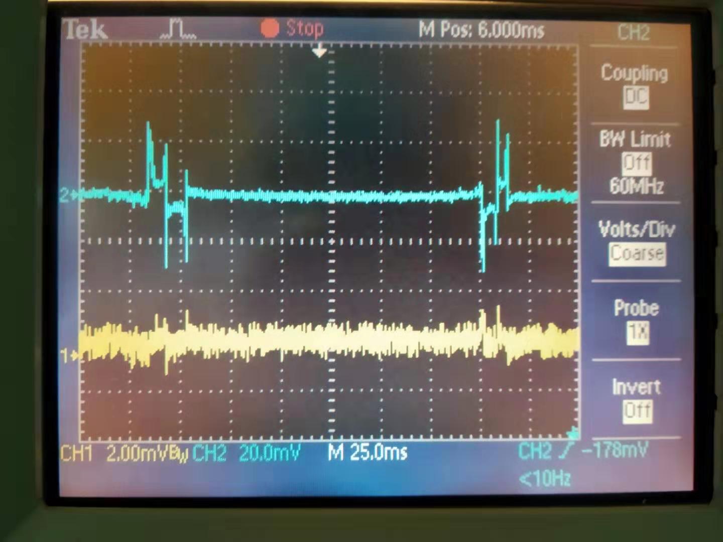
7. By using the same demodulator, we took RF signal from Qubig PD and quadrant and got PDH signal(see attached figure 1, blue curve is signal from Qubig, yellow curve is signal from quadrant). Note that green power on quadrant is ~1mW while green power on Qubig PD is ~200uW. So is seems quadrant is not so sensitive to green light or it doesn't have enough bandwidth.
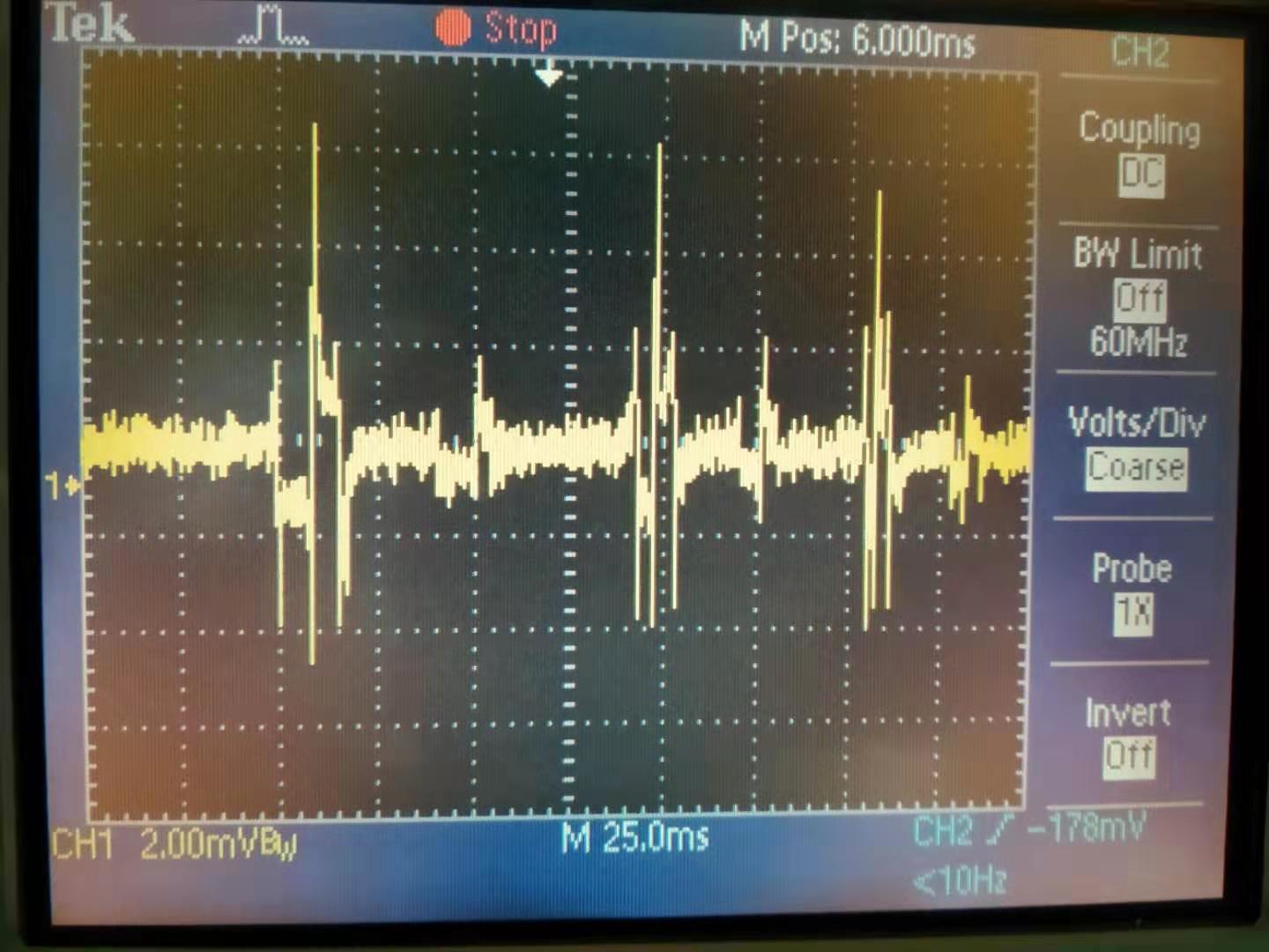
8. We also tried to move the beam totally on one quarter of quadrant. See attached figure 2. Roughly, the PDH signal was increased by a factor of 4.
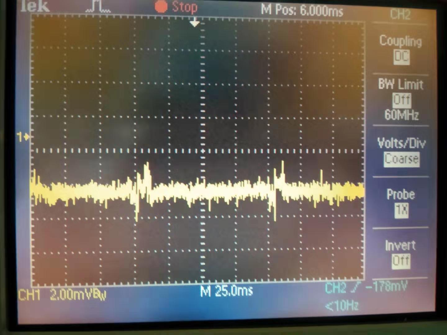
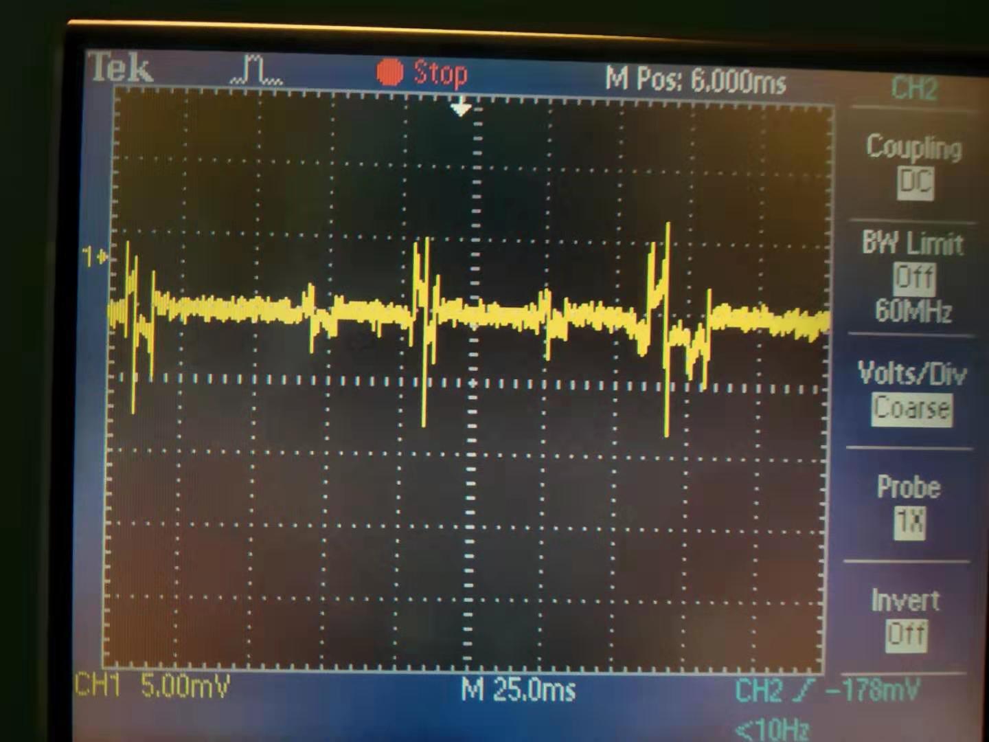
9. We also tried to check the other quadrant and the other demodulation board. I shows similar result. (Attached figure 3 shows PDH signal when beam is centered on quadrant, attached figure 4 shows PDH signal when the beam is mainly located in the first quarter of quadrant)
Above is the check we did on last Friday. Since quadrant worked well in NIKHEF, we will check again these days.