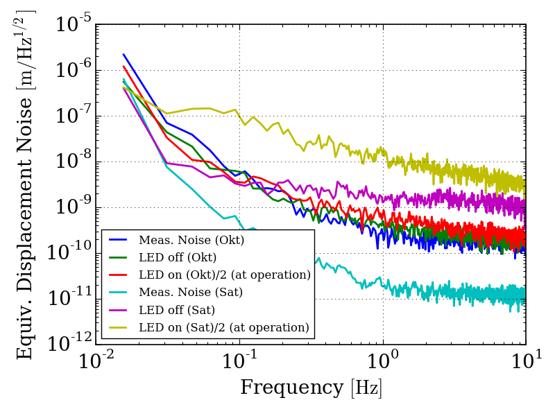
The attached graph shows noise level of two OSEM setups; with a satellite box (Sat) and with a test driver (Okt) made in NAOJ (design based on the Sat, but Akutsu chooses necessary/sufficient parts what he thought, and Okutomi made). Those two circuits supply different amount of DC current to the LED (TSTS7100). Exactly the same LED and PD combination is used for the measurements.
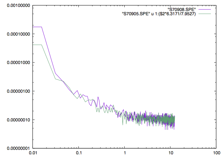
(0) The measurement systems's noise level (raw voltage noises) for both cases when the LEDs were turned off are in the same order of magnitude. (I don't mention the PD's noises here, and it will be mentioned in (1). I'm mentioning about the noise of measurement system with the range which is used when the PD circutis are measured. The second attached graphs are the raw voltage spectra (V/rtHz vs Freq), and showing this. S70908 (for the satellite box) measurement was done with 6.3mVpk range, while S70905 (for the Okt driver) was 7.95mVpk, and the ratio can explain the relation of both measurement noises) The difference shown are due to the difference between calibration factors (V/m) for the cases.
(1) Why are the PD noises (LED off) such different...?? For the Okt test driver, OP27G is used; for the satellite box, it seems OP2177. The transimpedances are the same (38.3k Ohm).
(2) The LED's intensity noises do not appear proportional to the DC powers. The displacement noises should be the same level if it is proportional.
(3) Additional Note: the satellite box's output of PD driver has a relatively large offset like 20mVdc even without any PDs are not connected, and which is not observed in the Okt test driver. I just add a 5.6k Ohm (by clips) parallely to the 38.3k Ohm and observed the offset decreases accordingly (38.3//5.6 = 4.88kOhm, and 38.3/4.88 = 7.84 times), and the same happens for the power spectrum of the intensity noise... so the offset would come from the opamp's current offset and current noise-like things. As was reported, some polarized capacitances are directed wrong, so some opamps would have malfunctinos now... I checked a OP2177's data sheet but cannot find descriptions on the current noise around low frequencies. The current offset is described but it is too low to explain what are happening here.
(4) Next I decied to use only the Okt test driver's PD circuit for evaluating what's going on the LED noise. With this driver, the larger (and non-proportionally large) noise of the LED driven by the satelite box is confirned again. The current to the LED would be now estimated to 88.3mA (the feedback loop makes 200//33 Ohms should be 2.5V)with the satellite box, and 8.3mA (the feedback loop makes 200+100 Ohms should be 2.5V) with the Okt test driver. This could explain, at least order, the rate why the output is 8.92Vdc for the satellite box and 740mVdc for the Okt. The intensity noise spectra are, however, not proportional to those DC voltages or current to the LEDs. Need to be more investigated; the goal would be to find the LED current setup in which the intensity noise would be slightly higher than the PD driver's noise; fortunately, I think the Okt circuit condition is very closed to this goal!
Anyway, generally speaking, I recommend to use a FET-input opamp for a transimpedance amplifier application like the PD driver circuit... as I did for the oplev QPD driver for KAGRA.
In order to see how the intensity noises of the LED (TSTS7100, not OP232) will change, I slightly modify the Okt driver. A trimmer (CT-94EW500-ohm) is attached to the driver so that the LED current can be variable. The attached graphs are the measurement results. According to the results, when the DC powers is over a certain level (in this case it is around 4Vdc... note that which is caught by the OSEM prototype setup, not the naked direct input power to the PD from the LED) , the intensity noises are not proportional to the DC intensities.
The followings can be said:
(1) because we don't want to input such a large current into vacuum, and the lowest usable DC current should be supplied to the LED (I still did not measure the trimmer's resistance). In terms of this, the DC current should be tuned to make the PD output to 1Vdc~2Vdc.
(2) If you are worrying about the other noises (scattering light of 1064nm, analog-to-digital noise, and ...) would cover the OSEM signals, the calibration factor (or sensitivity) of the OSEM should be kept high, meaning larger DC current to LED would be better. Then the maximum PD output would be (this is only my recommendation/suggestion) around 4Vdc.
My recommendation:
I like to setup the PD output to 1.5Vdc, which would be sufficient.