NaokiAritomi - 23:18, Wednesday 20 February 2019 (1228)
Re-alignment of homodyne
[Aritomi, Yuhang]
First, filter gain for IRMC was too high, so we changed it as follows.
Filter: gain 5, 20dB attenuator, 30 Hz lowpass
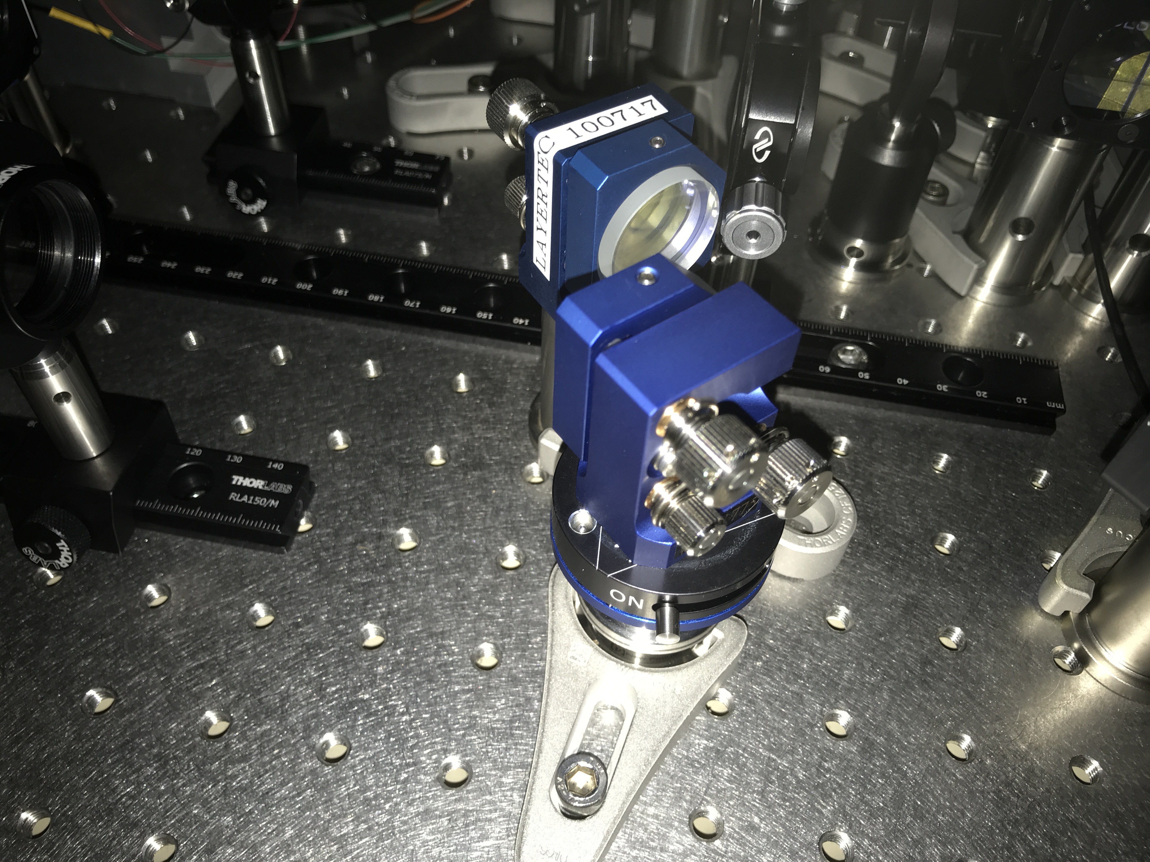
Then we replaced a flipping mirror which has a long micrometer with a new magnetic flipping mirror as shown in a first attached picture.
Alignment of LO to AMC somehow became worse, so we aligned it again. Main peak was 8.08V and mismatching peak was 3.6mV and 2.4mV. Mode matching is 8.08/(8.08+0.0036+0.0024) = 99.9%.
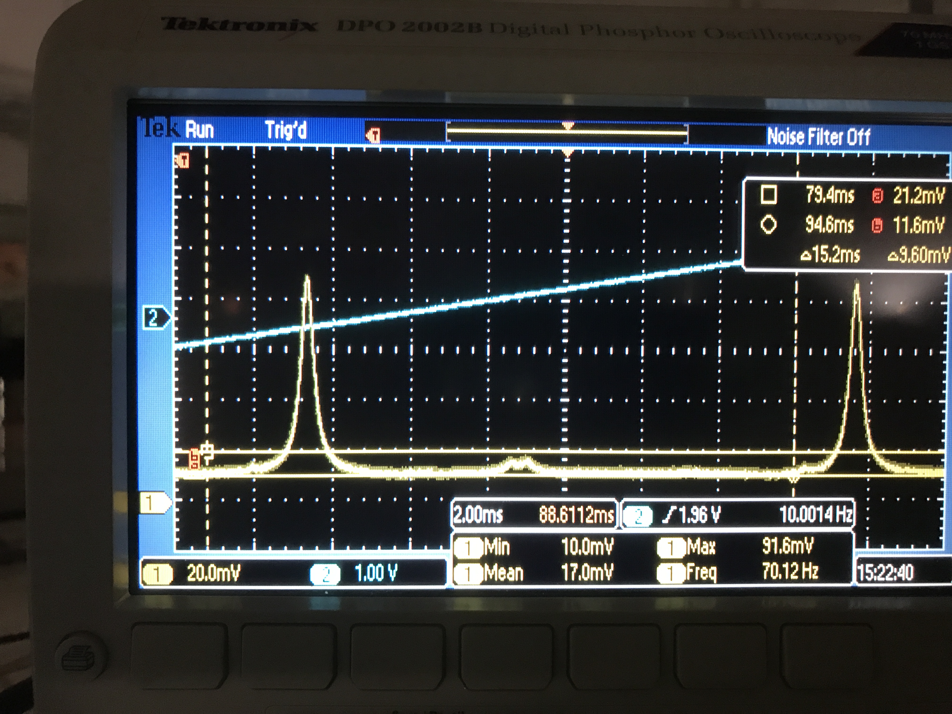
For alignment of CC to AMC, it has two mismatching peaks like second attached picture and they should be mode mismatch. Main peak was 83.2mV and two mismatching peak was 4.8mV, modemathing is 83.2/(83.2+0.48*2) = 89.7%.
Then we aligned flipping mirror before homodyne. Output of each homodyne PD is
PD 1: 4.85 V PD 2: -5.05 V
The unbalance is 0.2/5.05 = 4%. That's more or less same as before.
Finally we did a quick check of shot noise and squeezing. Shot noise of homodyne seems fine, but we couldn't see any squeezing. Tomorrow we'll check more detail.
The unbalance is 0.2/5.05 = 4%. Than's more or less same as before.
The unbalance is 0.2/5.05 = 4%. Than's more or less same as before.
Then We aligned flipping mirror before homodyne.
Output of each homodyne PD is
PD 1: 4.85V PD 2: -5.05V
The unbalance is 0.2/5.05 = 4%. Than's more or less same as before.
Images attached to this report